This thread has been locked.

If you have a related question, please click the "Ask a related question" button in the top right corner. The newly created question will be automatically linked to this question.

66AK2G12: Audio is interrupted while connecting to PC via USB

Part Number: 66AK2G12

Hi experts,

A customer of mine is using the 66AK2G as a USB-B (Device) to create a prototype board. Using the USB0/USB1 port, we are experiencing a problem where the audio from the PC application is interrupted when connected to the PC. There is no difference in Eye pattern between OK and NG boards.

I am referring to the datasheet, TRM, and High-Speed Interface Layout Guidelines, but I couldn't understand it from the documents alone, so please let me check.

Q1:Is there any register to adjust Receiver Sensibility on K2G side?
It seems that there is no such register in BOOTCFG_USB0_PHY_CTL0-4, so I would appreciate it if you could tell me how to adjust the receiver sensitivity of USB signal.

Q2: USBx_PHY_PC_TXRESTUNE in the BOOTCFG_USBx_PHY_CTLx register is used to adjust the DCR of the board and cable when it exceeds 45Ω.
Is this correct?

Q3: About USBx_PHY_PC_SQRXTUNE, what is the threshold that can detect about HS data? (=Specifically, what can it detect for HS data?)
There was a similar question in the following thread at the beginning, but there seemed to be no answer on how to use it.
e2e.ti.com/.../66ak2g12-controlling-rx-voltage-revel-for-detecting-usb-signal-via-bootcfg_usb0_phy_ctl2

Q4: Can you tell me more about the role of the USBx_TXRTUNE_RKELVIN pin? Also, is there any possible harm if the pattern from this pin to GND (including the "external resistor (REXT)") is long?

Best regards,
O.H

  • The PHY registers default to optimum values to be compliant to the USB specification. Therefore, we do not recommend changing any of these register values. The USB peripheral implemented in 66AK2G12 should not have any communication problems when connected to another device that is compliant to the USB specification with USB compliant cables and connectors.

    The best way to understand if the problem is related to USB communications would be connecting a USB protocol analyzer and observe the USB data stream when the audio drops occur. They may find the problem is not related to USB. It could be caused by many things, like buffer over-flow due to software overhead.

    Regards,
    Paul

  • I forgot to answer your question about the REXT connection. This signal trace should be short, so noise doesn't couple into the current mirror reference.

    Regards,
    Paul

  • Hi Paul,

    Sorry for late reply. We found a strange behavior when we investigated at the customer side, so please let us confirm it.

    [Details below]

    • The customer's board (abbreviated as "set" below) uses both USB0 and USB1 of K2G as Device ports.
    • Some sets have a problem with USB0, some with USB1. In normal temperature and high temperature, the reproduction rate is 100%, and the problem occurs only in either USB1 or ISB0 depending on the set.
    • The number of generated sets is 10/85.
    • The problem occurs even if the destination PC is changed.
    • There is no clear difference in the eye pattern between OK and NG Sets, but there are cases where USB packets are not being received properly. (This is determined by confirming that a receiving error has occurred in the software.)
    • The eye pattern is normal and there is no problem with the characteristic impedance of the transmission line of the USB D+/D- board, but the symptom occurs when using a long cable (4m).
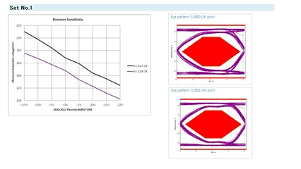
    • In order to investigate the cause of the problem, they performed the Reseiver Sensitibity Test using the test FW to adjust USB*_PHY_PC_SQRXTUNE, and checked if there was any change in the receive limit voltage and the squelch voltage.
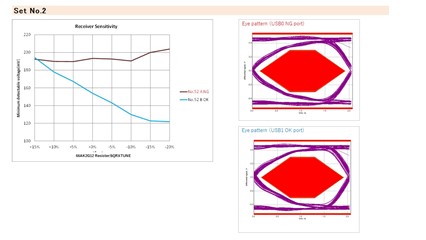
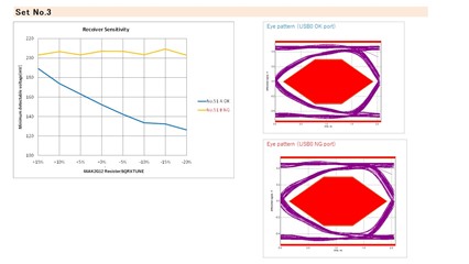
    • For the port with USB0/USB1 problem, even if USB*_PHY_PC_SQRXTUNE is changed, the receiving limit voltage and the squelch voltage of Receiver Sensitibity Test are not changed.
    • As a result of modifying the circuit to the minimum configuration that causes the problem in the set, they have confirmed that the problem is not with the peripheral components (common mode filter and USB switching IC), but with the set in which the K2G is mounted.
    • The cross-check on the IC itself is in progress and the result will be announced soon.
    • They are using TPS65911AA2NMAR for the start-up sequence, and there is no problem.(Please let me know if there is any power supply that may be related to this case.)

    The following is the information about the normal set, the set with the problem in USB0, and the set with the problem in USB1.

    [Question 1]
    They have set "BOOTCFG_USB*_PHY_CTL0~4" at the time of reset release after power-on from PMIC, is there any procedure or timing for setting USB*_PHY_PC_SQRXTUNE?

    [Question 2]
    Although there seems to be no problem in Errata, is there any example of trouble that the register settings cannot be reflected when BOOTCFG_USB*_PHY_CTL0~4 are changed from the default values at startup?
    They have confirmed that although the values are changed by reading the registers immediately after the register change, the receive limit voltage value of ReceiverSensitibity changes in the Ok set, but does not change in the NG set.

    [Question 3]
    As shown in sets 2 and 3 of the table, some of the receive limit voltages are high even at the default setting values. In this case, the receive sensitivity voltage could not be lowered even with the register setting. Is there any possible reason for this?

    [Question 4]
    Please tell me, what voltage value and how does it vary with the value of USB*_PHY_PC_SQRXTUNE(default and other adjustments), and the adjustment table when changing.

    We understand that these registers are used with default values. Whether or not I actually change these registers, as a customer I need this information as a clue to solving this problem. I would appreciate your cooperation.

    Best regards,
    O.H

  • I'm not going to discuss USB register functions, as their values should not be changed. Changing these register values is just going to make the problem worse.

    What makes the customer think their problem is related to USB signal integrity? Nothing you have shown indicates there is a signal integrity issue.

    As mentioned before, I feel they are wasting time with all of this signal integrity analysis.  The next step should be connecting a USB protocol/traffic analyzer and use it to understand where the USB communications is breaking.

    The problem they are experiencing is a system level issue which can only be understood by finding which hardware or software component in the system is causing the problem. It is good they have perform the signal level measurements and confirmed no signal integrity issues, but it may be time to move beyond that line of analysis and look elsewhere.

    Have they done any ABA testing where they swap components on working and non-working boards to determine is the problem moves with the component or stays with the PCB assembly?

    Regards,
    Paul

  • It is very unlikely the attached PC is producing signals anywhere near small enough to be approaching the minimum limits were RX sensitivity comes into play.

    They think they are having RX sensitivity, so lets makes sure they are performing the test properly.

    Ask them to provide an explanation of how they are performing RX sensitivity test and list the test equipment and test fixtures used for the test. The RX sensitivity values should be within the USB defined limits without them having to touch the registers. They think they are having RX sensitivity, so lets makes sure they are performing the test properly. 

    Go ahead and send me a snapshot of their schematic showing the USB signal connectivity between the USB connector and the 66AK2G12 device.

    Regards,
    Paul

  • Hi Paul,

    Thank you for your reply.

    I'm not going to discuss USB register functions, as their values should not be changed. Changing these register values is just going to make the problem worse.

    What makes the customer think their problem is related to USB signal integrity? Nothing you have shown indicates there is a signal integrity issue.

    They think the problem of signal integrity is directly related to the fact that the reception sensitivity varies from device to device. Additional experiments by a customer using a fixture board consisting only of 66AK2G and USB connector (USB switching IC, wire, and CMF were removed in the D+/D- line, and the USB compliance test fixture board was directly connected to the 66AK) confirmed the difference between devices. The details are described below.

    The voltage value shifts due to the loss of peripheral circuits, but the tendency of the problem symptom (i.e., the voltage does not change even if the SQRXTUNE setting is changed) does not change. When changing the SQRXTUNE setting, we have already confirmed that the register has been changed by reading the register. They suspect that this is due to a problem with the internal register settings and that the data is not being received.

    Q:Therefore, as a minimum, could you please tell me the voltage value of USB*_PHY_PC_SQRXTUNE when it is set to the default value (0x011)? They want to know if the default value is a reasonable value, regardless of whether they change it or not. If you can't, it would be helpful if you could tell us why.

    As mentioned before, I feel they are wasting time with all of this signal integrity analysis.  The next step should be connecting a USB protocol/traffic analyzer and use it to understand where the USB communications is breaking.
    Have they done any ABA testing where they swap components on working and non-working boards to determine is the problem moves with the component or stays with the PCB assembly?

    The ABA test (swap test) for K2G alone is in progress and the results will be available on 2/25. Depending on the results of these tests, we may consider going beyond the above steps.

    It is very unlikely the attached PC is producing signals anywhere near small enough to be approaching the minimum limits were RX sensitivity comes into play.

    They think they are having RX sensitivity, so lets makes sure they are performing the test properly.

    Ask them to provide an explanation of how they are performing RX sensitivity test and list the test equipment and test fixtures used for the test. The RX sensitivity values should be within the USB defined limits without them having to touch the registers. They think they are having RX sensitivity, so lets makes sure they are performing the test properly. 

    They perform general USB 2.0 compliance testing, and they do so with certified equipment. We will contact you with additional details.

    Q:Incidentally, what kind of testing is done at TI's production site for USB blocks when shipping ICs with K2G? I know you do not disclose the details, but it would be helpful if you could briefly tell us what range of contents you test.

    Go ahead and send me a snapshot of their schematic showing the USB signal connectivity between the USB connector and the 66AK2G12 device.

    We can share the schematics, but we would prefer to send them offline (private chat) since they contain customer information.

    I forgot to answer your question about the REXT connection. This signal trace should be short, so noise doesn't couple into the current mirror reference.

    Sorry for the additional question. They are aware of the above information, but this time, due to a mistake on the customer's side, the corresponding pattern is longer, and they would like to know if that is linked to this problem.

    Q:They assume it is related to USB D+/D- since it is a current mirror, but does this affect the waveforms of all D+/D- states (Eye related and other parts such as SOF)?

    As for our additional questions, some of them may be related to the ABA test results, but it would be helpful if you could tell us what you can answer.

    Best regards,
    O.H

  • I'm trying to find someone that knows what was tested during device characterization.

    Regards,
    Paul

  • Hi Paul,

    Thank you for the internal confirmation. I'm sorry for asking so many questions at the same time.

    As a quick update, the ABA test results showed that the problem was on the IC side. We could not find any problem in the schematic, so we would appreciate it if you could help us check the schematic.

    Also, the customer checked the protocol analyzer first. We will contact you with the results later, but there were some differences even just by looking at the first 500 packets. Based on these results, the customer assumed that the NG port was not receiving packets from the HOST correctly, and in addition, the Eye did not change between normal and faulty conditions (i.e., there was no problem with the output transmission line), so they started investigating Receiver Sensitivity as a parameter related to reception sensitivity.

    Best regards,
    O.H

  • If the signal coming out of the PC is compliant to the USB specification, it should not be approaching the squelch threshold of the receiver. Audio data is typically sent via an Isochronous data transfer protocol, which does have any error correction or re-transmit capability. So packets could be dropped if noise couples into the signal path and causes data corruption. I suspect this is more likely than the signal being attenuated enough that it drops below the receiver sensitivity.

    Regards,
    Paul

  • Hi Paul,

    Attached are the results of the protocol analyzer check, swap test, and the details of the receive sensitivity test.

    If these results and the schematic also indicate that the problem is caused by noise, could you give us your opinion on what might be the factor that makes it susceptible to noise? I would appreciate it if you could approve a friend request to share the schematic.

    Sorry for the additional question. They are aware of the above information, but this time, due to a mistake on the customer's side, the corresponding pattern is longer, and they would like to know if that is linked to this problem.

    Q:They assume it is related to USB D+/D- since it is a current mirror, but does this affect the waveforms of all D+/D- states (Eye related and other parts such as SOF)?

    Is it correct to say that the answer to the above question is yes, and that it may be directly related to this problem?

    Best regards,
    O.H

    66AK2G12_USB_Problem_20220225.xlsx