Part Number: TDA4VM
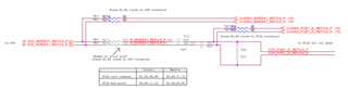
According to the routing PCIE reference clock externally, I set the PCIE clock to the external reference clock.
From the results of the read and write registers, it has been set successfully,
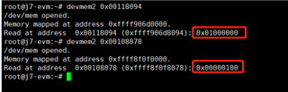
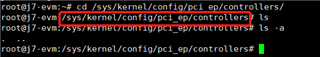
but in /sys/kernel/config/pci_ep/controller,there is no ep device.
I have three requestion:
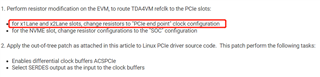
1、how to change resistors to "PCIe end point" clock configuration?
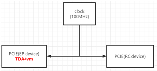
2、How the external reference clock is connected in hardware
3、Are there any other settings, including device tree, kernel configuration, etc.
tda4vm(as ep device) sdk=ti-processor-sdk-linux-j7-evm-08_00_00_08-Linux-x86-Install.bin(linux kernel version=5.10.41)
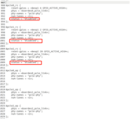
I change the device tree(k3-j721e-common-proc-board.dts). disable pcie0-2 rc model,enable pcie0-2 ep model