This thread has been locked.

If you have a related question, please click the "Ask a related question" button in the top right corner. The newly created question will be automatically linked to this question.

TMS320C6657: C6657 PCIe Power Sequence

Part Number: TMS320C6657

We are designing our customized C6657 board which has PCIe interface connection with PC.

PC works as RC, and DSP as EP.

The board is powered by PCIe slot of PC mother board. 

The boot mode is configured as PCIe boot via boot pins.

With reference to SPRAC59A PCIe FAQ Section 1.2 - Power Sequencing


The following steps show the power sequencing.
1. PCIe slot on the PC host provides power and reference clock to the PCIe module on the EVM.
2. PCIe boot code on the EVM initializes the C66x PCIe module and waits for the link coming up.
3. PCIe root complex (RC) in the PC host is powered up and a link is established between the PCIe RC in the host and PCIe end point (EP) in the EVM.
4. PC host enumeration (BIOS) starts to scan the PCIe bus.
5. PCIe end point in the EVM is enumerated and registered in the operating system (OS) of the host PC.

My question is: since DSP is powered by mother board, when PC power button is pressed, power will be fed to mother board and DSP at the same time.   Then how to guarantee Rom Boot Loader of DSP (Step 2) completes PCIe initialization task before RC power up in PC side (Step 3)?

Any design suggestion?

Thanks.

  • Hi Boll LI,

    Our PCI-E experts will be posting their Response ASAP.

    Thanks,

    Rajarajan U

  • Hi Boll LI,

    Kindly refer to this link, https://e2e.ti.com/support/processors-group/processors/f/processors-forum/352106/question-about-c6678-pci-express

    Though the link explains C6678 EVM, the same is applicable for C6657 also.

    Also, refer to "README.txt" in "{SDK_FOLDER}\pdk_c665x_2_0_16\packages\ti\drv\pcie\example\sample"

    Thanks,

    Rajarajan U

  • Hi Rajarajan,

    Unfortunately both the link and README.txt in the driver example do not answer my question.

    README.txt shows an example of PCIe connection between two EVM.  It is very obvious and easy to control the boot sequence of RC and EP.

    In the link, the autor mentioned "The working procedure is that the FPGA and the DSP are running before the PC is powered on".  Actually this is exactly what I am asking.  How to achieve this since DSP takes power from PC through PCIe slot?

  • Hi Boll LI,

    In the link, the autor mentioned "The working procedure is that the FPGA and the DSP are running before the PC is powered on".  Actually this is exactly what I am asking.  How to achieve this since DSP takes power from PC through PCIe slot?

    DSP and FPGA of the EVM are powered by a Power supply module and not by PCI-e Interface.

    Whether your setup has the following connection ?

    DSP -> PCI-e to AMC connector -> PCI-e -> Host.

    Thanks,

    Rajarajan U

  • Hi Rajarajan,

    No, there is no AMC connector in my board.

    My board is powered by PCIe interface.

    DSP ->  PCI-e -> Host.

  • Hi Boll LI,

    Could you able to give a diagrammatic representation of your connection. If possible, a picture of the setup also be good, could clarify my doubts.

    Thanks,

    Rajarajan U

  • Hi Rajaran,

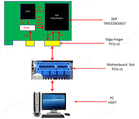
    The connection of my board is shown as below.

    DSP takes power (12V) from PCIe slot of motherboard.

    To rephrase my question: when PC power supply button is pressed, BIOS will run and start to scan/enumerate PCIe device after some time.  In the meantime, DSP will also start to boot (RBL in PCIe boot mode) under the power sheme and initialize PCIe peripheral.  My doubt is how to make sure RBL is alive before BIOS start to enumerate.  BIOS and DSP are competing the time.

  • Hi Boll LI,

    Thanks for the detailed diagram.

    From the diagram, I can understand it is a custom board. With C6657 EVM, we advise using the setup in the following connection, with C6657 EVM -> AMC to PCI-e converter -> PCI-e HOST.

    I do not have PCI-e setup now. With my hardware team's help, will reproduce this scenario and provide a response.

    Thanks,

    Rajarajan U

  • Dear Boll, 

    In your description:

    >1. PCIe slot on the PC host provides power and reference clock to the PCIe module on the EVM.

    you did not mention that the host also controls the PERST signal on the PCI slot. So I assume the C6657's PCIe interface is fully controlled by the EVM PCIe boot sequence, independent of the host. Therefore, there is a race condition that the PCIe lanes are not enabled on the EVM, when the PC BIOS is booted. Thus it will not detect the PCIe device on the slot. 

    If you have any tools on the host PC to view the boot log or PCIe status to see if the PC has detected the endpoint, then you try to rescan the PCIe bus, to see if the host can re-enumerate the device. 

    Since each PC's BIOS boot varies, can you check your PC boot log (if you can) to see if the host detected a device in the slot? The equivalent Linux commands are: 

       echo 1 > /sys/bus/pci/devices/0000:00:00.0/remove (shown NVME node, replace the device node if using other slots)

       echo 1 > /sys/bus/pci/rescan

    though I am not sure your host is Linux or Window. 

    If you are building a production system with the EVM and want to properly configure the hardware, you may want to:

    1. Modify the EVM so that the PCIe reset signal is controlled by the PERST on the slot. That way the PC will issue a fundamental reset to the EP's PCIe interface. Sometimes we put a DIP switch on the EVM to set the mux source of the PCIe reset. sorry I have not checked C6657 EVM schematics. 
    2. If the PC did not detect the EVM when it boots, that means the EVM's boot sequence had not enabled PCIe lanes when the PC deasserted fundamental reset, thus the system violated the spec of "system must enter LTSSM DETECT state within 20ms of the deassertion of PERST". In this case, you may put a termination of the PCIe Lane 0 signals, that will allow the PC to detect the device when the EVM is booted.

    let us know if these notes help or further discussion is needed. 

    Jian 

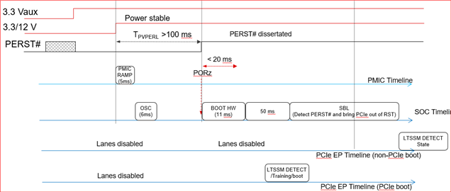
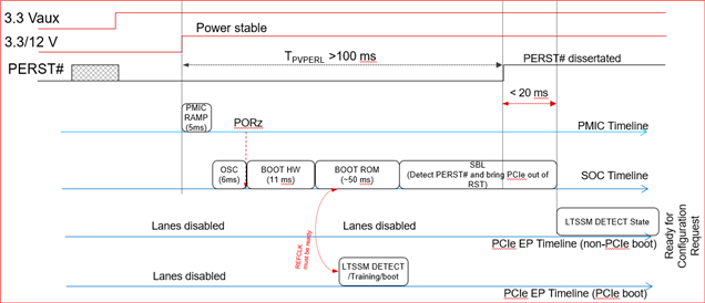
  • Add a timing diagram from another device for reference. Please ignore boot time numbers, they are not for C6657.

    Case 1: LTSSM timed out, PCIe device not detected.

    Case 2. Device enters LTSSM within 20ms of PERST deassertion. Device detected. 

    Jian

  • Dear Jian,

    Your answer exactly hits the point.

    Let me supplement some information regarding my board.
    1. I am designing my new custom board, with reference to the EVM. The board is still in design stage.
    2. The host is Windows OS.
        In my understanding, in Windows PC, PCIe device will be scanned only once by BIOS. Rescan is not supported.
        So the DSP boot timing must fulfil the requirement as illustrated in Case 2.
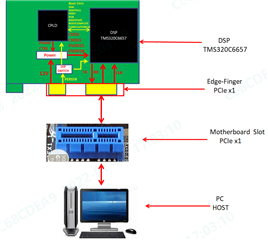
    3. In my design, PERST signal of PCIe slot is connected to both CPLD and RESETFULL pin of DSP, and muxed via DIP, as shown in the picture below.
        The reason is that from relevant materials I could not clearly identify which path to go, so I just reserve both paths for futural testing.

    To make more inquiries.
    1. Could you provide the time numbers of BOOT HW and BOOT ROM for C6657?

    2. In your post you mentioned "Sometimes we put a DIP switch on the EVM to set the mux source of the PCIe reset. "
        Could you further explain what the principle/rule is to select the source of PCIe reset?

    3. Compare Case 1 and Case 2, the key difference is whether PERST de-asserting and PORz are synchronized or not.
        Could you elaborate what the hardware difference is for these two cases?
        What is the connection of PERST signal in each case?

    Thanks.