This thread has been locked.

If you have a related question, please click the "Ask a related question" button in the top right corner. The newly created question will be automatically linked to this question.

TMS320C6657: GPIO Driver issue with GPIO17

Part Number: TMS320C6657

I have been working with the GPIO driver for the C6657 and was having issue getting it to control pins that were shared with the Timer.  I have configured the GPIO driver with 

...

GPIO_PinConfig gpioPinConfigs[] =
{
GPIO_DEVICE_CONFIG(0,   1) | GPIO_CFG_OUTPUT, //This is the pin shared by the GPIO01/BOOTMODE00
GPIO_DEVICE_CONFIG(0, 17) | GPIO_CFG_OUTPUT, //This is the pin shared by the TIM1/GPIO17
};

void Board_GPIO_Init ( void )
{
// NOTE: a structure GPIO_v0_config needs to be defined for this
// driver to compile
GPIO_init(); // Initialize the GPIO system

GPIO_write(0, 0);  // Set GPIO01  low
GPIO_write(0, 1);  // Set GPIO01  high

GPIO_write(1, 0);  // Set GPIO17  low
GPIO_write(1, 1);  // Set GPIO17  high

}

...

When I execute the GPIO01 writes the pin follows the controls.  However, when I execute the GPIO17 writes the pin is not controlled.

After researching this a little I have found that if I configure the PIN_CONTROL_0 register with (0x20000), the GPIO driver properly controls the pin.

Questions:

  1. Have I missed something in the GPIO's driver configuration? (Is there somewhere in the documentation that these steps are described?)
  2. Is there a different driver that controls the pin mux? (If so, what is it?)

Thanks,

Brad

  • Brad,

    Rajan is working on your post.

    Thanks for your patience.

    Regards

    Shankari G

  • Hi Brad,

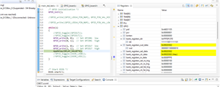
    I have included your code changes and It is working fine for me. I am verifying the GPIO from "bank_register_out_data" from the register view.

    and the code changes are "main_led_blink.c"

    int main(void)
    {
        /* Call board init functions */
        Gpio_appC7xPreInit();
        Board_initGPIO();
        
         /* GPIO initialization */
        GPIO_init();
        
        while(1)
        {
            GPIO_write(0, 0);  // Set GPIO01  low
            GPIO_write(0, 1);  // Set GPIO01  high
    
            GPIO_write(1, 0);  // Set GPIO17  low
            GPIO_write(1, 1);  // Set GPIO17  high
            AppDelay(DELAY_VALUE*4);
        }

    "GPIO_board.c"

    GPIO_PinConfig gpioPinConfigs[] =
    {
        GPIO_DEVICE_CONFIG(0,   1) | GPIO_CFG_OUTPUT, //This is the pin shared by the GPIO01/BOOTMODE00
        GPIO_DEVICE_CONFIG(0, 17) | GPIO_CFG_OUTPUT, //This is the pin shared by the TIM1/GPIO17
    };    
        

    "GPIO_board.h"

    #if defined (evmC6657)
    #define GPIO_LED1_PIN_NUM           (1U)
    #define GPIO_LED1_PORT_NUM          (0U)  /* GPIO port 0 */
    #define GPIO_LED17_PIN_NUM          (17U)
    #define GPIO_LED17_PORT_NUM         (0U)  /* GPIO port 0 */
    #endif

    Thanks,

  • Ranjett,

    With the code you presented, I agree with your results.  The bank_register_out_data register values change.  However, the physical pin does not follow the bank_register_out_data register values.  

    I found that the Pin Control 0 (PIN_CONTROL_0) Register needs to have the pin configured for GPIO operation for the GPIO system to control the upper pins, ie. GPIO 16 to 31.  After setting this register the bank_register_out_data register can control the state of the upper GPIO pins.

    To restate my questions:

    1. Is the GPIO driver supposed to properly configure the upper 16 bits of GPIO, ie. pins 16 to 31, for GPIO operation when the user configures the GPIO driver to control pins 16 to 31 for GPIO operation?
      1. If so, What is the proper syntax to do this?
    2. Is there a different driver that configures the pin mux registers or has it been left for the programmer to properly configure the pin mux registers?

    Thanks, 

    Brad

  • Hi Brad,

    The bank_register_out_data register values change.  However, the physical pin does not follow the bank_register_out_data register values

    I will modify the Register and probe GPIO hardware responses in my C6657 EVM.

    I found that the Pin Control 0 (PIN_CONTROL_0) Register needs to have the pin configured for GPIO operation for the GPIO system to control the upper pins, ie. GPIO 16 to 31.  After setting this register the bank_register_out_data register can control the state of the upper GPIO pins.

    To modify "PIN_CONTROL_0" you can directly write to the Register address. Please follow the link,

    https://e2e.ti.com/support/processors-group/processors/f/processors-forum/1113523/tms320c6657-how-to-access-gpio-pins-through-the-registers-for-tms320c6657

    1. Is there a different driver that configures the pin mux registers or has it been left for the programmer to properly configure the pin mux registers?

    There is SYS/BIOS and CSL APIs which were the methods to access the peripherals. We can also use the direct above method to write to the particular address.

    Thanks

  • So... to summarize the thread.

    1. The GPIO driver is a multiplatform driver that does not handle all of the differences between the platforms.  Some of the peculiarities of the platform, like the pin mux on the C6657 are not handled by the driver.  So to use the driver to control the C6657's GPIO pins 16 and above, the user is required to set the appropriate bits in the PIN_CONTROL_0 register.  Which is documented in the datasheet and not replicated with a note in the GPIO driver.
    2. This register (PIN_CONTROL_0) is not defined in the PDK's GPIO or other header files. (ie. the user is required directly access this register or set up a bit definition for this register.)
    3. The banks_register_out_data register does not show the value of the physical pin.
  • Brads,

    Rajan will probe the Physical pin and check the value shows up or not.

    Thanks for your patience

    Regards

    Shankari G

  • Hi Brad,

    • This register (PIN_CONTROL_0) is not defined in the PDK's GPIO or other header files. (ie. the user is required directly access this register or set up a bit definition for this register.)

    Yes, In PDK, PIN_CONTROL_0 APIs were not present. To solve your issue, I have simplified the code, without using GPIO API, there is no modification on "GPIO_board.c" and "GPIO_board.h" required.

    
    #define GPIO_BASE (0x0232000)
    #define GPIO_DIR_OFFSET (0x10)
    #define GPIO_SETDATA_OFFSET (0x14)
    
    //pincontrol 0 for GPIO 16 to 31
    #define PIN_CONTROL_0 (0x02620580)
    
    int main()
    {
        volatile uint32_t *gpio_reg, *pin_mux_reg;
    
        //pin mux code for gpio29
        //for GPIO0 to GPIO15, following mux configuration not required.
        pin_mux_reg = (volatile uint32_t *)(PIN_CONTROL_0);
        UART_printf("\n value before in (PIN_CONROL_0) = 0x%X \n", *pin_mux_reg);
    
        *pin_mux_reg |=  (1 << 16); // To configure GPIO16
        UART_printf("\n value after in reg_val Direction register = 0x%X \n", *pin_mux_reg);
    
    
        //gpio pin set direction as output and control GPIO16
        gpio_reg = (volatile uint32_t *)(GPIO_BASE + GPIO_DIR_OFFSET); 
        UART_printf("\n value before in (GPIO_BASE + GPIO_DIR_OFFSET) = 0x%X \n", *gpio_reg); 
    
        *gpio_reg &= ~ (1 << 16); // configure as output pin -- write 0 to the Direction register 0x0232 0010 for GPIO16
        UART_printf("\n value after in reg_val Direction register = 0x%X \n", *gpio_reg);
    
        
        /*
    
        *gpio_reg &= ~ ((1 << 29) | (1 << 14)); // configure as output pin -- write 0 to the Direction register 0x0232 0010 for GPIO14 and GPIO 29 in single line
        UART_printf("\n value after in reg_val Direction register = 0x%X \n", *gpio_reg);
    
        */
    
    
        gpio_reg = (volatile uint32_t *) (GPIO_BASE + GPIO_SETDATA_OFFSET); 
        UART_printf("\n value before (GPIO_BASE + GPIO_SETDATA_OFFSET) = 0x%X \n", *gpio_reg);
        // Write value 1 in the set data register
    
        *gpio_reg |= (1 << 16); // to set data on gpio pin 29 as 1 -- write 1 to the SET register 0x0232 0014 
        UART_printf("\n value after in reg_val set data register = 0x%X \n", *gpio_reg);
    
    
        //gpio pin set direction as output and control GPIO14 before
        gpio_reg = (volatile uint32_t *) (GPIO_BASE + GPIO_SETDATA_OFFSET); 
        UART_printf("\n value before (GPIO_BASE + GPIO_SETDATA_OFFSET) = 0x%X \n", *gpio_reg);
    
        // Write value 1 in the set data register
        *gpio_reg |= (1 << 16); // to set data on gpio pin 14 as 1 -- write 1 to the SET register 0x0232 0014 
        UART_printf("\n value after in reg_val set data register = 0x%X \n", *gpio_reg);
    
    }


    Please try this code and confirm whether you can able to control GPIO16.

    Thanks,