This thread has been locked.

If you have a related question, please click the "Ask a related question" button in the top right corner. The newly created question will be automatically linked to this question.

AM6442: AM64x & PTP features

Part Number: AM6442

Dear Sitara champs,


About the AM64x supported PTP features

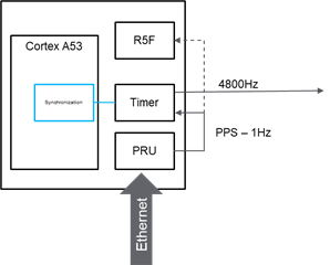
Question 1/ How many PPS signals is it possible to generate through the PRU/CPSW synchronized with PTP clock ?

Question 2/ Is it possible to generate 1Hz and 4800Hz ie 2 signals synchronized with the PTP clock?


In this application the 1Hz signal would be mainly used  by internal R5F cores.

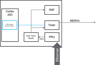
Question 3/ So, instead of generating a dedicated output signal, is it possible to generate an IRQ to a specific R5F core ?

This way would save pins by avoiding to generate an output pin signal which will would be connected to an AM64x input pin


Thank you!


Best regards,

Guillaume

  • Hello Guillaume,

    The hardware is capable of outputting multiple PPS signals from a single input signal through the time sync router. The signal should be able to be routed either to a SYNC_OUT pin, or another part of the processor, with the time sync router. Note that additional Time Sync Router information was recently added to the AM64x TRM, so please check to make sure you are using the latest version before trying to look up inputs / outputs information.

    At this point I am not sure if software allows for the "one input to multiple outputs" configuration. For some information on time sync router that I have not updated in a while, please reference this e2e post: https://e2e.ti.com/support/processors-group/processors/f/processors-forum/1061474/faq-am64x-what-is-the-time-sync-router-for-how-do-i-use-it

    For question 2, I would need to take a look at exactly how we are generating the PPS signal. I would expect that the CPTS could generate multiple outputs (a different frequency output from different GENF outputs), but I am not sure whether we have a software framework to do that, or if that would have to be custom code.

    One of my team members is trying the PPS output example right now. I will check with them to see if they have any additional notes on top of what is already written in the SDK docs: https://software-dl.ti.com/processor-sdk-linux/esd/AM64X/08_04_01_04/exports/docs/linux/Foundational_Components/Kernel/Kernel_Drivers/Network/CPSW3g.html#common-platform-time-sync-cpts-module

    Regards,

    Nick

  • Hello Nick,

    Thank you for your answer.

    Concerning the first part of your answer:

    Not sure to clearly understand how the Time Sync Router is able to "intercept" output from PRU-ICSSG to another part of the chip. I suppose that PRU-ICSSG manage its own SYNC_OUT signal according to the PTP frames and synchronization steps. I don't understand how the Time Sync Router is able to catch this outpout and spread it to other part of AM64xx. 

    The question 2 is more specific to our application and what we want: generate both 1Hz (PPS) and 4800Hz synchronized togeter with PTP1588. For that I suppose that only PRU-iCSSG firwmware is capable to do it. The time Sync Router will not allow us to perform such behavior (or maybe get the PPS from PRU and start and internal Timer with a frequency of 4800Hz and resynchronize it at each event of PRU/PPS.... Quite complex for me :/

    If you can check if the PRU firmware is capable to supply several signals with different frequency, it will be great Slight smile

    Regards,

    Guillaume

  • Hello Nick,

    Did you have the opportunity to check with your team the ability to generate multiple pps with different frequency and if it is available in the software framewok ?

    Thank you,

    Regards,

    Guillaume

  • Hello Guillaume,

    Thank you for the ping.

    Summary 

    CPSW ethernet can definitely route a 1 pulse per second signal to multiple outputs. The CPTS hardware is physically capable of generating different output pulses on different GENF outputs, but I do not think there is Linux software support for configuring multiple GENF output signals.

    PRU Ethernet supports PTP. However, I am not sure if PPS output from PRU Ethernet is currently supported on AM64x. Still researching.

    Routing a PPS signal to multiple targets - with CPSW 

    Let's start by looking at generating a PPS output with CPSW. Documentation is at https://software-dl.ti.com/processor-sdk-linux/esd/AM64X/08_04_01_04/exports/docs/linux/Foundational_Components/Kernel/Kernel_Drivers/Network/CPSW3g.html#common-platform-time-sync-cpts-module . In particular, look at section "PPS Pulse Per Second support". The section is a bit out of date, so I just filed some tickets to get it updated. The biggest update is the the time sync router registers are NOT firewalled any more, so you CAN route a single input signal to multiple outputs (i.e., a single signal can "sync" multiple targets).

    However, this is the important part:

    If you go to the devicetree file of the EVM you are using, you will see that the CPSW's PPS signal is getting sent out through the time sync router.

    Let's assume you are using k3-am642-evm.dts. See this section?

    &timesync_router {
            pinctrl-names = "default";
            pinctrl-0 = <&mcu_cpts_pps>;
    
            /* Example of the timesync routing */
            mcu_cpts_pps: mcu-cpts-pps {
                    pinctrl-single,pins = <
                                    /* pps [cpts genf1] in22 -> out37 [cpts hw8_push] */
                                    TS_OFFSET(37, 22)
                                    /* pps [cpts genf1] in22 -> out25 [SYNC1_OUT pin] */
                                    TS_OFFSET(25, 22)
                                    >;
            };
    };
    

    That tells us that the Linux driver is configuring the CPSW PPS signal to come out of the GENF1 output of the CPSW's CPTS counter. That one input signal to the time sync router is getting routed to 2 outputs: the CPTS HW8_PUSH input, and the SYNC1_OUT pin.

    I imagine the signal is getting looped back to the same CPTS to enable the test in section "Example of using Time stamp external events" (easier than asking the customer to attach a signal generator to the EVM). The SYNC1_OUT pin can be attached to an oscilloscope to see the output sync signal.

    So to send a PPS signal from the CPSW Ethernet to an R5 core, you would need to set the time sync router to send the PPS signal to the DMASS0_INTAGGR_0, and then configure that interrupt aggregator to route the signal to the R5. At this point in time I have not looked at configuring the DMASS0_INTAGGR_0.

    Ok, what about the other options? 

    What about outputting a 4.8kHz sync signal?

    As far as I am aware, the Linux PTP / PPS drivers have no visibility into the TI-specific hardware that implements the PPS signal. So I do not think the Linux driver is capable of configuring other regular signals at a frequency other than once a second. Still following up with the developers for more info.

    What about PRU Ethernet with PPS output?

    At some point in the past, it looks like PPS output was supported on AM65x PRU Ethernet: https://software-dl.ti.com/processor-sdk-linux/esd/AM64X/08_04_01_04/exports/docs/linux/Foundational_Components/PRU-ICSS/Linux_Drivers/PRU_ICSSG_Ethernet.html#pps-pulse-per-second-support. However, I have not seen any evidence that this was tested on AM64x. When I look at the AM65x Linux devicetree, I do not see the kind of configuration I would expect to see. I have not had time to try to test on the latest AM65x release at this point in time.

    I am also following up with the developers on the question about PRU Ethernet.

    Regards,

    Nick

  • the

    Hello Nick,

    Thanks again for your very detailled answer Slight smile

    For the moment, I will focus on the PRU Ethernet parts since it seems that we will use also the HSR standard (not the current subject).I understand that, technically, the PRU is able to generate a PPS since its work (worked ?) on AM65xx and test on am64xx is still pending.In case where it is not possible to generate both signals with PRU (PPS + 4.8Khz), what do you recommand for achieve such solution ?

    From what I understand, I can guess almost 2 solutions:

    1/ Generate a PPS from hardware pin a routing it to another gpio connected to a AM6xx timer. The timer is responible to generate a pulse @4800Hz.

    To ensure synchonization between the PPS and the 4800Hz, an irq handler must be developped to adjust the frequency of 4800Hz according to the PPS.

    The timer capture the time at PPS time. Compare the delta time between the capture and remain time to the next period and then recompute the frequency of timer on the fly to get 4800 pulse in the second.

    2/ Using the Time Sync Router to avoid to "externalize" the PPS but the rest of the process is the same than solution 1.

    What do you think ?

    Regards,

    Guillaume

  • Hello Guillaume,

    1) What kind of HSR is the customer expecting to use over PRU Ethernet? 100Mbit HSR/PRP with processing offload on the PRU cores can technically run on AM64x (the firmware was originally developed for PRU-ICSS on AM335x), but we do not provide any documentation for running it and I am not sure whether we actually validate it. Gigabit HSR/PRP is not currently supported on AM64x. I am not sure of the plans for gigabit HSR/PRP with PRU offload, if your customer is looking at gigabit HSR/PRP I'll need to connect you with another member of our team.

    2) What is the 4.8kHz signal being used for?

    Regards,

    Nick

  • Hello Nick,

    1. For HSR, we plan to use it in 100Mbps network with offload support

    2. The final objective is to synchronize all ADC across the network (<4us).  For that, the plan was to use the PTP protocol to get the highest precision possible and benefits the PPS signal to synchronise all the ADCs. The best way for me was to have a PPS at 4800Hz which correspond to the sampling rate of all ADC and trigger those ADC a the same time. In other word, having a 4800hz signal synchronized with the PPS output to trigger all the ADCs.

    Regards,

    Guillaume

  • Hello Guillaume,

    At a hardware level, the PRU IEP timer is capable of outputting a periodic signal that is 4.8kHz. However, at this point in time the 100MBit HSR/PRP PRU firmware does not have that as an option. The PRU-ICSS 100Mbit generic Ethernet firmware is publicly available at https://git.ti.com/cgit/processor-sdk/pdk/tree/packages/ti/drv/emac/firmware/icss_dualmac. As far as I am aware, the HSR/PRP firmware source code is not publicly available, though you can download the binaries from here: https://www.ti.com/tool/PRU-ICSS-INDUSTRIAL-SW

    The easiest option is probably to send the 1PPS pulse through the time sync router to synchronize the counters on different cores, and then use the core to generate the 4.8kHz pulse (e.g., with a timer).

    Since you are planning on using 100MBit HSR/PRP firmware on AM64x, I am reassigning your thread to another team member with more experience on HSR/PRP to comment on whether much has changed from the AM335x SDK 6.3 docs (which is the last SDK release with official support for PRU HSR/PRP firmware as far as I am aware): https://software-dl.ti.com/processor-sdk-linux/esd/docs/06_03_00_106/AM335X/linux/Industrial_Protocols_HSR_PRP.html ).

    Regards,

    Nick

  • Hello Nick,

    As far as I understand, it is not possible with PRU 100mbps to generate a 4800 synchronized with the PPS. I think that, for my requirements, I need to syntonize the 4800HZ with the PPS signal: I mean, generate 4800 pulses within the PPS. For that, I think that I need to correct the frequency of the "4800Hz" to fit the 4800 pulses within the PPS. 

    Like this, All ADC in the system should sampling at the same time.

    To go deeper in that subject, I think I need to organize a workshop with my FAE. The main topic of this thread was to know if it is possible to pRU to generate multiple output with different frequency synchronized with PTP.

    Little question: the PRU from AM335x support several priorities queues on Rx and TX  (4 queues for each). This is still the case for AM64xx and it is supported by linux driver / TI-RTOS ?

    Guillaume

  • Hi Guillaume,

    We use the PRU to generate multiple output frequencies by reading the IEP timer (synchronized over PTP), and programing the PRU IEP Compare registers to generate events based on the timer value. These events can be routed to interrupts or pins using the Compare Event Interrupt Router.

    Note you'll need to manually increase the IEP Compare registers each time an event occurs to "move it forward" so the event is triggered periodically instead of just once. We use an unused PRU core to do this, but conceivably you could use any core that can read and write the IEP Compare registers.

  • Hello Steven,

    Thank you for the tips Slight smile

    Since you manage the output signal by another PRU core which do not have IRQ I believe, you need to poll event of IEP compare register which introduce a jitter at resynchronization of the output signal no ?

    If it is the case, do you know the jitter introduced by the time to reschedule the IEP compare register ?

    After some thinking, I believe that just generating a 4800Hz adjust at each 1Hz will not be enough for my application. Indeed, since we need to ensure that 4800Hz is the same between the devices, I need to syntonize the 4800hz according to the top of 1Hz.

    By syntonize, I mean: 

    The larger of PPS is the same between all the devices, but, if I just start a 4800Hz and resynchronize it at each PPS, the 4800Hz will drift across the device since the quartz and AM64x tolerences will generate different 4800Hz and the drift at the end of the PPS will be probably too large. To compensate the drift due to tolerence of components, I need to generate a 4800Hz according to the larger of the PPS received.

    At each PPS, I need to adjust the number of tick corresponding to generate 4800 pulses within the PPS.  Due to timer precision (32bits) and the number of pulse, I will probably need to compensate some pulse by adding or remove a timer tick.

    Do you have similar approch ?

    Regards,

    Guillaume

  • Hi Guillaume,

    We use the Compare Event Interrupt Router to generate an interrupt, so there is no additional polling jitter on the event. We do use the PRU core to poll, but only to determine when to schedule the next event. As long as you move the compare registers forward before the next event occurs, there is no additional jitter caused by polling since the event is triggered in hardware. You could also remove the polling altogether by updating the compare registers in the interrupt handler triggered by the event, like this:

    Compare Event ==> Interrupt Router generates interrupt ==> Interrupt handler updates IEP Compare registers to schedule next event

    There is latency introduced by the interrupt router, but according to this thread it's on the order of tens of nanoseconds. I assume most of that latency is fixed and could be compensated out by scheduling the compare event "early", although we haven't yet benchmarked this to confirm.

    In your case assuming a 250MHz IEP clock, you might write 250,000,000 to the IEP CMP1 register (schedules 1st PPS event) and 52083 to the CMP2 register (schedules 1st 4800 Hz event). When you detect that the IEP timer has exceeded 52083 (either by polling or by receiving the interrupt), you can write 104167 to CMP2 to schedule the 2nd 4800Hz event and so on. When the IEP counter reaches 250,000,000, you will likewise need to write 500,000,000 to CMP1 to schedule the 2nd PPS event. This method keeps the PPS and 4800Hz in sync since they are both scheduled from the same IEP clock.

    Depending on how much jitter you can tolerate, you may also need to syntonize clocks at the Ethernet PHY level ("SyncE"). This will reduce jitter due to PTP adjustment on the IEP clock.

  • Hi Steven,

    I think I understand what you mean by generate the PPS and the 4800 through the IEP timers.

    But (always a but), I'm not sure to fully understand few points:

    1. The PPS synchronized with PTP: I assume that the PRU core managing the PTP use one of the CMP register to generate the PPS. By definition, this PPS always drift and is always corrected by the PTP. So, sometime, the number of ticks to generate the PPS will be > 250,000,000 and other times, it will be less than 250,000,000 ticks. This is managed autmatically by the PRU when the PTP clock passed the second to "59 ->00".

    The number of tick used by the IEP timer to generate the PPS will be different at each second and for each device/product in the PTP network. For example: for the Device 1, the PPS is 250,000,025 ticks

    for the Device 2, the PPS is 249,999,996 ticks.

    Due to tolerance of quartz and chip itself, the time of a ticks is not the same from one device to another.

    2. To have the closest 4800Hz across devices/product, I need to match the 4800Hz to the PPS and not with the IEP clock.

    I mean, If I generate a 4800Hz only based on the IEP clock, due to drift/correction on the PPS signal, I can probably generate more pulse  within the PPS than necessary.

                 For device 1: if the PPS last 250,060,000 ticks => I will generate 4801 pulses within the PPS.

    On the other hand, If I compute the 4800Hz against the PPS larger:

                  For device 1: if the PPS last 250,060,000 ticks => 250,060,000 / 4800 = 52096 ticks

    At each PPS, I need to recompute the number of ticks for the 4800Hz => I need to reduce the latency between the IRQ of the PPS and when I update the CMP2 register to generate the 4800Hz (at least, for each IRQ of PPS)

    Am I wrong somewhere ? In any case, I need to dedicate a core to generate the 4800Hz.

    Regards,

    Guillaume

  • Hi Guillaume,

    A lot of this depends how much jitter your application can tolerate.

    If the jitter introduced by clock drift and adjustment is too high for your application, you could implement Synchronous Ethernet (SyncE). This is where you take the recovered RX clock from the upstream PHY (typically in combination with a jitter cleaner) and route this clock as an external input to the IEP clock and downstream PHYs. This ensures that all boards are syntonized since their IEP clocks are driven by the same clock (no frequency difference between boards). There will be phase shift between boards, but the PTP algorithm should bring their phases into alignment so all IEP clocks reach 250,000,000 within +/- 1 clock period.

  • Hi Steven,

    I never heard before of the SyncE feature. I will try to go into details of the Synchonous Ethernet and verify jitter tolerences which can be acceptable between products.

    Thank you a lot for your support Slight smile

    Regards,

    Guillaume

  • Guillaume,

    Are there still open items? Or were you able to proceed.

      Pekka

  • Hi Pekka,

    I'm not able to proceed to generate multiple pps completely but it is not necessary anymore.

    The subject can be closed. (I don't know how)

  • Ok I'll close this thread.