This thread has been locked.

If you have a related question, please click the "Ask a related question" button in the top right corner. The newly created question will be automatically linked to this question.

PROCESSOR-SDK-AM62X: GPIO Interrupts

Part Number: PROCESSOR-SDK-AM62X
Other Parts Discussed in Thread: SK-AM62

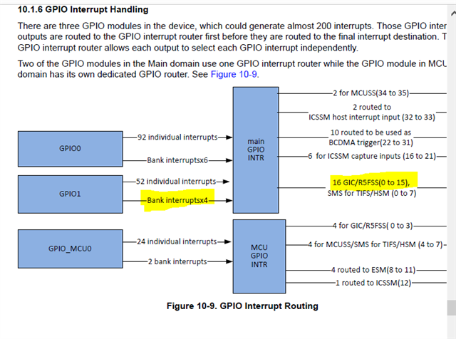
I am attempting to get a design up and going that uses GPIO based interrupts.  We are wanting to leverage GPIO1_44-47 as interrupts.  I have been referring to two specific examples, but neither seem to work.

The first example that I tried is found in the Processor SDK QNX 08_05_00_0.  Specifically it is the psdkqa\qnx\examples\gpio example.  When I attempt to port that to our design I am able to build successfully, but the first attempt to write to a GPIO_MUX_BASE_PHY_ADDR register location results in an "Unhandled Exception" error that causes the unit to crash.

After doing some E2E research, it seemed we might need to use SCI to configure the interrupt router, but it's not clear why that is not the method used for the SDK.  Based upon https://e2e.ti.com/support/processors-group/processors/f/processors-forum/1176076/processor-sdk-am62x-gic-interrupts/4469253?tisearch=e2e-sitesearch&keymatch=gpio%25252525252520%25252525252526%25252525252526%25252525252520interrupt#4469253

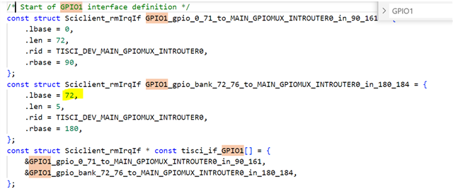
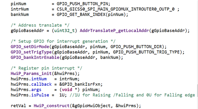
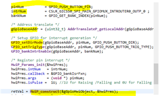
we have implemented the following code that I think should configure the interrupt router:

static void Sciclient_gpioIrqSet(void)
{
    int32_t                             retVal;
    struct tisci_msg_rm_irq_set_req     rmIrqReq;
    struct tisci_msg_rm_irq_set_resp    rmIrqResp;

    rmIrqReq.valid_params           = 0U;
    rmIrqReq.valid_params          |= TISCI_MSG_VALUE_RM_DST_ID_VALID;
    rmIrqReq.valid_params          |= TISCI_MSG_VALUE_RM_DST_HOST_IRQ_VALID;
    rmIrqReq.global_event           = 0U;
    rmIrqReq.src_id                 = TISCI_DEV_MAIN_GPIOMUX_INTROUTER0; //MCU_GPIO_MUX_INT_ROUTER_ID;
    rmIrqReq.src_index              = 134U;//SRC_IDX_BASE_MCU_GPIO_BANK_0;
    rmIrqReq.dst_id                 = TISCI_DEV_MAIN_GPIOMUX_INTROUTER0; //MCU_GPIO_MUX_INT_ROUTER_ID;   // TISCI_DEV_MAIN_GPIOMUX_INTROUTER0 ?
    rmIrqReq.dst_host_irq           = 32U; //MCU_GPIOMUX_INTROUTER_MCU_0_OUTP_6;
    rmIrqReq.ia_id                  = 0U;
    rmIrqReq.vint                   = 0U;
    rmIrqReq.vint_status_bit_index  = 0U;
    rmIrqReq.secondary_host         = TISCI_MSG_VALUE_RM_UNUSED_SECONDARY_HOST;

    retVal = Sciclient_rmIrqSetRaw(&rmIrqReq, &rmIrqResp, -1);

    if(0 != retVal)
    {
        cout << "[Error] Sciclient event config failed!!!  RetVal=" << retVal << endl;
        //DebugP_log("[Error] Sciclient event config failed!!!\r\n");
        //DebugP_assert(FALSE);
    }

    return;
}

Using this code results in an error message: [Error] Sciclient event config failed!!!  RetVal=-1.  Further exploration of SLOG shows that every execution of the function results in a new entry in SLOG: Jan 05 18:52:59.587 tisci_mgr.323598 slog 55
ti_sci_msg_xfer (252): sciclient service call failed on ACK

Can someone please direct me towards an example that will work for an AM62x design?

Thanks,

John 

  • Hi John,

    I have taken your inputs and I will update you.

    Regards,

    Vaibhav

  • Hi Vaibhav I'm working with John on this feature and I have some questions as well with regards to the MCU+SDK and the PSDK v8.5. Some of the constants and register addresses don't seem to match the TRM.

    For example, in the MCU+SDK in cslr_intr_mcu_m4fss0_core0.h, the WKUP_MCU_GPIOMUX_INTROUTER0_OUTP_6 constant is defined as 2, but in the TRM it is defined as 80 in table 10-15.

    In the PSDK under examples/gpio/src/gpio.c I believe GPIO_MUX_BASE_PHY_ADDR and GIC_ICFG_BASE_PHY_ADDR don't match the TRM. There also seems to be 8 GPIO addresses, where the AM62x only has 3 (2 Main GPIO and 1 MCU GPIO). I'm confused by the value GPIOMUX_INTRTR0_OUTP_8, in the example it is defined as 392, but this value doesn't seem to exist in the TRM. The closest I was able to find was MAIN_GPIOMUX_INTROUTER0_OUTP_7 in table 10-15 as these indexes are 0 based, and the interrupt ID is 215. Finally I'm having trouble finding documentation regarding how mux_offset is created. The comments say "GPIOMUX_INTRTR0_MUXCNTL_n, where 'n' is the INTRTR0_OUT 8:63 ... IRQ 392:447" but I don't see these values in the TRM, or why the interrupt variable needs to be multiplied by 4.

    Thanks for your help!

  • Any updates to provide yet?

    Thanks,

    John

  • Hi John,

    I have read your query.
    It sounds like you are running into an issue with configuring the interrupt router on your design when trying to use GPIO1_44-47 as interrupts. It seems that the example in the Processor SDK QNX 08_05_00_0 is not working as expected and you are encountering an "Unhandled Exception" error.

    Pease allow me sometime to look into this and I will get back to you after discussing the issue with the relevant team member.

    Thanks,

    Vaibhav

  • Hello John,

    Can you please use the code below and confirm if GPIO interrupts work on GPIO1_44-47?

    In the interrupt routine, please make sure to check which GPIO pin caused the interrupt.

    Let me know if you encounter any issues. If this works, I can explain each line of code.

    Alternatively, we have an FAQ on how to route GPIO interrupts on AM64, but not on AM62.

    I will try to create one in the future to help other customers to fix routing GPIO interrupt issues.

    static void Sciclient_gpioIrqSet(void)
    {
    int32_t retVal;
    struct tisci_msg_rm_irq_set_req rmIrqReq;
    struct tisci_msg_rm_irq_set_resp rmIrqResp;

    rmIrqReq.valid_params = 0U;
    rmIrqReq.valid_params |= TISCI_MSG_VALUE_RM_DST_ID_VALID;
    rmIrqReq.valid_params |= TISCI_MSG_VALUE_RM_DST_HOST_IRQ_VALID;
    rmIrqReq.global_event = 0U;
    rmIrqReq.src_id = TISCI_DEV_MAIN_GPIOMUX_INTROUTER0;
    rmIrqReq.src_index = 182U;
    rmIrqReq.dst_id = TISCI_DEV_MAIN_GPIOMUX_INTROUTER0;
    rmIrqReq.dst_host_irq = 34U; //34U or 35U ;
    rmIrqReq.ia_id = 0U;
    rmIrqReq.vint = 0U;
    rmIrqReq.vint_status_bit_index = 0U;
    rmIrqReq.secondary_host = TISCI_MSG_VALUE_RM_UNUSED_SECONDARY_HOST;

    retVal = Sciclient_rmIrqSetRaw(&rmIrqReq, &rmIrqResp, -1);

    if(0 != retVal)
    {
    cout << "[Error] Sciclient event config failed!!! RetVal=" << retVal << endl;
    //DebugP_log("[Error] Sciclient event config failed!!!\r\n");
    //DebugP_assert(FALSE);
    }

    return;
    }

    Regards,

    S.Anil.

  • Using the suggested adjustments I still get the same error message: [Error] Sciclient event config failed!!!  RetVal=-1.

    John

  • I have also tried and got the same result. I'm using the Uboot files provided in the TI SK-AM62 SD card image and stopped Uboot right before it tried to load Linux. Then I loaded an unmodified QNX IFS and ran sciclient_app with your suggested Sciclient_gpioIrqSet function. Here was the output:

    # /tmp/tisci-mgr
    # /tmp/sciclient_app
    main: Sciclient_init complete
    DMSC Firmware Version 8.4.7--v08.04.07 (Jolly Jellyfi
    Firmware revision 0x8
    ABI revision 3.1
    A53 Core0 Freq = 1250 MHz
    [Error] Sciclient event config failed!!! RetVal=-1


  • Hello John,

    I have confirmed in my end, I am not able to get the  [Error] Sciclient event config failed!!!  RetVal=-1. issue.

    I created this example in the M4 domain and routed a GPIO1 bank of interrupts to the M4 core as the destination core in MCU+SDK.

    Could you please tell me which core you want to route the GPIO interrupts to either R5F or A53 or M4 domain ?

    Regards,

    S.Anil.

  • We are trying to route the interrupt to the A53 domain.

    John

  • Hello John,

    Please use the code I've shared below, based on MUC+SDK.

    If it doesn't work, let me know and we'll need to check your QNX code.

    static void Sciclient_gpioIrqSet(void)
    {
    int32_t retVal;
    struct tisci_msg_rm_irq_set_req rmIrqReq;
    struct tisci_msg_rm_irq_set_resp rmIrqResp;

    rmIrqReq.valid_params = 0U;
    rmIrqReq.valid_params |= TISCI_MSG_VALUE_RM_DST_ID_VALID;
    rmIrqReq.valid_params |= TISCI_MSG_VALUE_RM_DST_HOST_IRQ_VALID;
    rmIrqReq.global_event = 0U;
    rmIrqReq.src_id = TISCI_DEV_MAIN_GPIOMUX_INTROUTER0;
    rmIrqReq.src_index = 182U;
    rmIrqReq.dst_id = TISCI_DEV_MAIN_GPIOMUX_INTROUTER0;
    rmIrqReq.dst_host_irq = 0U; //0U or 1U or 2U or 3U ;
    rmIrqReq.ia_id = 0U;
    rmIrqReq.vint = 0U;
    rmIrqReq.vint_status_bit_index = 0U;
    rmIrqReq.secondary_host = TISCI_MSG_VALUE_RM_UNUSED_SECONDARY_HOST;

    retVal = Sciclient_rmIrqSetRaw(&rmIrqReq, &rmIrqResp, -1);

    if(0 != retVal)
    {
    cout << "[Error] Sciclient event config failed!!! RetVal=" << retVal << endl;
    //DebugP_log("[Error] Sciclient event config failed!!!\r\n");
    //DebugP_assert(FALSE);
    }

    return;
    }

    Regards,

    S.Anil.

  • Same result. What code are you needing to check?  There isn't a whole lot beyond what is shown.  Is there something in the setup that we might be missing?  Wrong version of tisci-mgr?  Something else?

    John

  • Hello John,

    Thanks for the update .

    When we want to enable the GPIO interrupt on AM62X, we should enable the Interrupt Router based on the destination core.

    Typically, the Interrupt Router should be configured from the SCI client function.

    Is it possible to share your project with us?

    I need to look at your project and configure the SCI client function to resolve the issue quickly.

    Regards,

    S.Anil.

  • Hello John,

    I have reviewed your log and it appears to not match my proposal.

    I assume that the log was recorded based on your SCI client settings.

    Can you please confirm if the below settings are being used in your code?

    If not, can you share the SCI code settings for the logged data?

    rmIrqReq.valid_params = 0U;
    rmIrqReq.valid_params |= TISCI_MSG_VALUE_RM_DST_ID_VALID;
    rmIrqReq.valid_params |= TISCI_MSG_VALUE_RM_DST_HOST_IRQ_VALID;
    rmIrqReq.global_event = 0U;
    rmIrqReq.src_id = TISCI_DEV_WKUP_MCU_GPIOMUX_INTROUTER0; //MCU_GPIO_MUX_INT_ROUTER_ID;
    rmIrqReq.src_index = 182U;//SRC_IDX_BASE_MCU_GPIO_BANK_0;
    rmIrqReq.dst_id = TISCI_DEV_WKUP_MCU_GPIOMUX_INTROUTER0; //MCU_GPIO_MUX_INT_ROUTER_ID; // TISCI_DEV_MAIN_GPIOMUX_INTROUTER0 ?
    rmIrqReq.dst_host_irq = 32U; //MCU_GPIOMUX_INTROUTER_MCU_0_OUTP_6;
    rmIrqReq.ia_id = 0U;
    rmIrqReq.vint = 0U;
    rmIrqReq.vint_status_bit_index = 0U;
    rmIrqReq.secondary_host = TISCI_MSG_VALUE_RM_UNUSED_SECONDARY_HOST;

    0x5D4A00B6: Resource Management/FAIL(Action failed): IRQ_IR_CFG(Configured IR input to output mapping): IR input index: 182

    0x5B070000: Resource Management/FAIL(Action failed):         IRQ_SET(Program interrupt route): upper 16-bits of valid_params: 0x0000

    0x5B080003: Resource Management/FAIL(Action failed):         IRQ_SET(Program interrupt route): lower 16-bits of valid_params: 0x0003

    0x5B0E0005: Resource Management/FAIL(Action failed):         IRQ_SET(Program interrupt route): Source device ID: 5

    0x5B0F00B6: Resource Management/FAIL(Action failed):         IRQ_SET(Program interrupt route): Source index: 182

    0x5B100005: Resource Management/FAIL(Action failed):         IRQ_SET(Program interrupt route): Destination device ID: 5

    2. Can you also provide the log for the following settings?

    rmIrqReq.valid_params = 0U;
    rmIrqReq.valid_params |= TISCI_MSG_VALUE_RM_DST_ID_VALID;
    rmIrqReq.valid_params |= TISCI_MSG_VALUE_RM_DST_HOST_IRQ_VALID;
    rmIrqReq.global_event = 0U;
    rmIrqReq.src_id = TISCI_DEV_GPIO1;
    rmIrqReq.src_index =74U;
    rmIrqReq.dst_id = TISCI_DEV_GICSS0;
    rmIrqReq.dst_host_irq = 32U;
    rmIrqReq.ia_id = 0U;
    rmIrqReq.vint = 0U;
    rmIrqReq.vint_status_bit_index = 0U;
    rmIrqReq.secondary_host = TISCI_MSG_VALUE_RM_UNUSED_SECONDARY_HOST;

    retVal = Sciclient_rmIrqSet(&rmIrqReq, &rmIrqResp, SystemP_WAIT_FOREVER);

    3. I am not an expert in QNX, and I am working with QNX experts to resolve the issue. Additionally, would it be possible for you to share your code with us for further debugging at our end?

    Regards,

    S.Anil.

  • Hello John,

    I heard from Mukul that you are able to run the SCI client function without getting any SCI errors, but you are unable to get an interrupt on the GPIO1_44 to 47 pins.

    May I know what your requirements are? Do you want to get an interrupt in Edge trigger or Level trigger? This needs to be specified to the GIC.

    /* Register pin interrupt */
    HwiP_Params_init(&hwiPrms);
    hwiPrms.intNum = intrNum;
    hwiPrms.callback = &GPIO_bankIsrFxn;
    hwiPrms.args = (void *) pinNum;
    hwiPrms.isPulse = 1U; //1U for Raising /Falling and 0U for Level Trigger

    retVal = HwiP_construct(&gGpioHwiObject, &hwiPrms);

    In our RTOS code, we have a hwiPrms structure, and in that, we can specify all the parameters related to the GPIO interrupt. See the code above.

    I am not aware of the QNX code, do we have a similar structure in QNX to configure the GPIO interrupt parameters? If so, please configure the GPIO interrupt parameters as shown above.

    By the way, rmIrqReq.src_index = 74U is configured for the Register bank interrupt, so you will only get one interrupt.

    In the interrupt routine, make sure to check which GPIO pin caused the interrupt.

    If you want to create individual interrupts, you can change rmIrqReq.src_index = 44U from rmIrqReq.src_index = 47U, so that you can get a callback for each interrupt. I will explain all the SCI parameters once the issue is resolved.

    Please let me know if you face any issue.

    Regards,

    S.Anil.

  • Hi Swargam,

    We are still working to register the interrupts with QNX. While we do see INTSTATUS change when we trigger an interrupt it does not trigger an event in QNX. I don't think we'll be able to use the code you provided since QNX has its own APIs, but we will direct our questions to them. We would still like to understand the difference between the examples in your last message and why one uses  TISCI_DEV_WKUP_MCU_GPIOMUX_INTROUTER0 and the other uses TISCI_DEV_GPIO1. Thanks.

  • Hello Dan ,

    I have followed the below procedure for configuring the GPIO interrupt based on MCU+SDK.

    You can also follow the same procedure in QNX.

    Procedure for GPIO Interrupt configurations

    1. GPIO Configuration: Configure the GPIO pin as an input.
    2. Destination Core Identification: Identify the destination core to route the GPIO interrupt to, which can be either the M4F, A53, or R5F.
    3. Interrupt Router Configuration: Configure the interrupt router output based on the destination core. Currently, this information is not configurable in the system config, so you need to follow the procedure below to manually configure the interrupt router output.
    4. Enable the bank interrupt or individual pin interrupt, trigger type and interrupt number based on your requirements.

    Example : You want to enable an interrupt on GPIO1_44 to GPIO1_47 and the destination core is A53."

    Step 1: Configure the GPIO pin as an input.

    Step 2: Configure GPIO Interrupt Router and select Destination core

    We need to configure four parameters in the Sciclient_gpioIrqSet(void) function:

    rmIrqReq.src_id , rmIrqReq.src_index , rmIrqReq.dst_id and rmIrqReq.dst_host_irq.

    You want to get an interrupt on GPIO1, so source ID would be TISCI_DEV_GPIO1.

    rmIrqReq.src_id = TISCI_DEV_GPIO1;

    You want to generate an interrupt for Register Bank 2. According to the TRM, to get a bank interrupt on Bank 2, the source index would be 182. More details about the GPIO Interrupt source index can be found under Chapter 10.1.6, "GPIO Interrupt Handling".

    Please go to the file at C:\ti\mcu_plus_sdk_am62x_08_05_00_14\source\drivers\sciclient\soc\am62x\sciclient_irq_rm.c.

    When you want to enable the Bank 2 interrupt, you have to write the index value as 74 (72 is the base value + 2 for the Bank 2 interrupt, as per the rm_irq.c file)."

    rmIrqReq.src_index = 74U;

    As per the TRM, according to the below GPIO interrupt routing diagram, all GPIO1 interrupts are routed to the M4/GIC/R5F domains, and the interrupt router is shared with other cores as well.

    In this case, the destination ID would be the core where you want to route the GPIO interrupt, either it is A53 or R5F.

    As per your requirement, the destination ID would be the A53 core. So,

    rmIrqReq.dst_id = TISCI_DEV_GICSS0;

    The next step is to select the Interrupt Router Register from 0 to 15.

    I selected rmIrqReq.src_index to be 0 to 15 based on the file at C:\ti\mcu_plus_sdk_am62x_08_05_00_14\source\drivers\sciclient\sciclient_default_boardcfg\am62x\sciclient_defaultBoardcfg_rm.c.

    rmIrqReq.src_index = Base Value + Interrupt Router Index;

    You can choose an Interrupt Router Index value from 0 to 15.

    The base value is 32, since all GIC SPI interrupts start from 32.

    rmIrqReq.dst_host_irq = 32U;


     Step 3: Enable the bank interrupt or individual pin interrupt, trigger type and interrupt number .


    Note:

    1. If you want to enable the interrupt for each individual interrupt instead of bank interrupts, you must follow the steps below.

    In the following parameter, you must specify the pin number instead of the register bank number:

    1. src_index = Pin Index;


    Do not call the following function:

    1. GPIO_bankIntrEnable(gGpioBaseAddr, bankNum);


    In the ISR routine, instead of using the bank register status and clear, use the following functions:

    1. GPIO_clearIntrStatus and GPIO_getIntrStatus.

    If the interrupt router is shared between different cores, use the following function.

    retVal = Sciclient_rmIrqSet(&rmIrqReq, &rmIrqResp, SystemP_WAIT_FOREVER);

    If the interrupts are routed to only a single core and not routed to other cores as well, use the following function.

    retVal = Sciclient_rmIrqSetRaw(&rmIrqReq, &rmIrqResp, SystemP_WAIT_FOREVER);

    Please let me know if you need any other help.

    Regards,

    S.Anil.

  • Hello Dan/John ,

    The Interrupt Router Register cannot be configured manually. It must be configured through the DMSC core. If you attempt to write to the Interrupt Router Register from A53 or other cores, the SOC will enter an exception state.

    Except this register you can manually write to all other GPIO registers  .

    Regards,

    S.Anil.

  • Swargam,

    I think in general we are following the process you describe.  However it seems the details you are providing aren't quite correct for our setup.  The SCI server in the DMSC will not successfully receive the source/destinations you recommend.  As of now the only setup that we have had the SCI server in the DMSC accept is:

    • src_id: TISCI_DEV_MAIN_GPIOMUX_INTROUTER0
    • src_index: 134 (GPIO1.gpio.44 from Table 10-10)
    • dst_id: TISCI_DEV_MAIN_GPIOMUX_INTROUTER0
    • dst_id: 0 (We think this translates to Gicss0.spi.32 based on Table 10-13).

    We have setup the GPIO correctly to assert upon a falling edge of GPIO_44.  As Dan mentioned we have confirmed this by looking at the appropriate GPIO_INTSTAT23 (0x60105C) register.  What we didn't know yesterday, but do now is that as long as we have the GPIO set correctly the GPIO_INTSTAT23 register will reflect the interrupts status regardless of the router setup that we do via the SCI server in the DMSC.   This leads us to believe that we still don't have something in the routing setup correct.  We have wondered are there multiple levels of the routing that we need to be doing (instead of just one).  We also wonder if there is some GIC setup that we are missing. We do think that using GIC interrupt 32 (Table 10-13) with a QNX InterruptAttach call should be the appropriate interrupt call.  We have working code that uses the I2C GIC interrupt 193.

    In order to abstract this from the software level can you please provide the appropriate registers and register settings that need to be used to route a falling edge interrupt from GPIO1_44 to GIC interrupt 32.  We fully understand that some of these registers will not be directly accessible.  This will allow us to confirm that our software is doing what we think it is doing.

    Regards,

    John


  • Hi John,

    Thanks for the update.

    I have a few questions. Can you please provide your inputs?

    • src_id: TISCI_DEV_MAIN_GPIOMUX_INTROUTER0
    • src_index: 134 (GPIO1.gpio.44 from Table 10-10)
    • dst_id: TISCI_DEV_MAIN_GPIOMUX_INTROUTER0
    • dst_id: 0 (We think this translates to Gicss0.spi.32 based on Table 10-13).

    After the above settings, what are the values of the two addresses 0x00A00000 and 0x00A00004?

    Which SCI client function are you using:

    Sciclient_rmIrqSet(&rmIrqReq, &rmIrqResp, SystemP_WAIT_FOREVER) or

    Sciclient_rmIrqSetRaw(&rmIrqReq, &rmIrqResp, SystemP_WAIT_FOREVER)?

    In our MCU+SDK, to set the trigger type for A53, we will be using the following two functions.

    As per your comments, I understand that you want to get a falling edge on the GPIO1_44 pin. To achieve this, you can use the function  HwiP_setEdgeSpiIntrType(uint16_t intrNum)" and pass 32U as the interrupt number.

    To compile the below code in your QNX software, you should have the definitions of the CSL_gic500_gicdRegs structure and other structures.

    If you have them, you can directly use the code. Otherwise, try to integrate the attached .h file and compile it

    #define HWIP_GIC_BASE_ADDR              (0x1800000UL)
    #define HWIP_GICD_SPI_INTR_ID_MAX       (992u)
    #define HWIP_GICD_SGI_PPI_INTR_ID_MAX   (32u)


    static int32_t HwiP_setEdgeSpiIntrType(uint16_t intrNum)
    {
        CSL_gic500_gicdRegs *gicdRegs = (CSL_gic500_gicdRegs *)(HWIP_GIC_BASE_ADDR);
       
        uint32_t index, mask;

        if ( intrNum < HWIP_GICD_SPI_INTR_ID_MAX )
        {
            /* Transform Interrupt ID */
            intrNum -= HWIP_GICD_SGI_PPI_INTR_ID_MAX;

            index = intrNum / 16u;
            mask = 0b11 << ((intrNum % 16u) * 2u);

            gicdRegs->ICFGR_SPI[index] = gicdRegs->ICFGR_SPI[index] | mask;
        }
        else
        {

        }

        return SystemP_SUCCESS;
    }


    static int32_t HwiP_setLevelSpiIntrType(uint16_t intrNum)
    {
        CSL_gic500_gicdRegs *gicdRegs = (CSL_gic500_gicdRegs *)(HWIP_GIC_BASE_ADDR);
       
        uint32_t index, mask;

        if ( intrNum < HWIP_GICD_SPI_INTR_ID_MAX )
        {
            /* Transform Interrupt ID */
            intrNum -= HWIP_GICD_SGI_PPI_INTR_ID_MAX;

            index = intrNum / 16u;
            mask = 0b11 << ((intrNum % 16u) * 2u);

            gicdRegs->ICFGR_SPI[index] = gicdRegs->ICFGR_SPI[index] & (~mask);
        }
        else
        {

        }

        return SystemP_SUCCESS;
    }
    Regards,
    S.Anil.
  • Hello John,

    cslr_gic500.h

    The above .h file is based on the AM64X platform, and the MCU+SDK for the AM62X platform does not support the A53 architecture.

    Therefore, I cannot share the AM62X cslr_gic500.h file.

    However, I have found an alternative solution that involves writing directly to the register level instead of using the above .h file.

    After reviewing the register sets for both the AM62X and AM64X platforms, I have discovered that the GICs for both platforms are located at the same address space.

    Therefore, you can use the following function to select the trigger type .

    #define HWIP_GIC_BASE_ADDR              (0x1800000UL)
    #define HWIP_GICD_SPI_INTR_ID_MAX       (992u)
    #define HWIP_GICD_SGI_PPI_INTR_ID_MAX   (32u)
    static int32_t HwiP_setEdgeSpiIntrType(uint16_t intrNum)
    {
        //CSL_gic500_gicdRegs *gicdRegs = (CSL_gic500_gicdRegs *)(HWIP_GIC_BASE_ADDR);
       
        uint32_t index, mask;


        if ( intrNum < HWIP_GICD_SPI_INTR_ID_MAX )
        {
            /* Transform Interrupt ID */
            intrNum -= HWIP_GICD_SGI_PPI_INTR_ID_MAX;


            index = intrNum / 16u;
            mask = 0b11 << ((intrNum % 16u) * 2u);


            //gicdRegs->ICFGR_SPI[index] = gicdRegs->ICFGR_SPI[index] | mask;
         *( (uint32_t  *)  ( HWIP_GIC_BASE_ADDR  +  (0xC08U + ((index  )*0x4U)) ) )  |= mask;
        }
        else
        {


        }


        return SystemP_SUCCESS;
    }
    Please let me know if you need any other help.
    Regards,
    S.Anil.
                                 
  • After the above settings, what are the values of the two addresses 0x00A00000 and 0x00A00004?

    0xA00000: 0x66948100

    0xA00004: 0x00010086

    Which SCI client function are you using:

    Sciclient_rmIrqSet(&rmIrqReq, &rmIrqResp, SystemP_WAIT_FOREVER) or

    Sciclient_rmIrqSetRaw(&rmIrqReq, &rmIrqResp, SystemP_WAIT_FOREVER)?

    Sciclient_rmIrqSetRaw

    I have tried both your iterations of HwiP_setEdgeSpiIntrType and both create segment faults.  I have noticed that the code is trying to set 0x1800c08 to 0x3.  However readback seems to indicate that bit 0 is not writable (0x1800C08 = 0x2).  Can you comment?

    Regards,

    John

  • 0xA00000: 0x66948100

    0xA00004: 0x00010086

    Hello John,

    Based on the above register values, you have selected the router output to be zero and have properly configured pin 134 .

    I have tried both your iterations of HwiP_setEdgeSpiIntrType and both create segment faults.

    However, it seems that you are unable to write the value 0x03 to the address 0x1800C08.

    Before addressing this issue, I would like to confirm how you enabled the yellow lines marked in the picture .


    Regards,

    S.Anil.

  • Hello John,

    May I know how you implemented the function below in your QNX?

    This function is used to enable GIC interrupt types, set interrupt priorities, enable interrupts, and register user callbacks.

    Would it be possible for you to share an example of your GPIO code?

    This way, we can quickly attempt to solve the problem if the below solution does not work."

    int32_t HwiP_construct(HwiP_Object *handle, HwiP_Params *params)
    {
    HwiP_Struct *obj = (HwiP_Struct *)handle;
    uint8_t coreId;

    DebugP_assertNoLog( sizeof(HwiP_Struct) <= sizeof(HwiP_Object) );
    DebugP_assertNoLog( params->callback != NULL );
    DebugP_assertNoLog( params->intNum < HwiP_MAX_INTERRUPTS );

    coreId = Armv8_getCoreId();

    gHwiCtrl.isr[params->intNum] = params->callback;
    gHwiCtrl.isrArgs[params->intNum] = params->args;

    /* Set interrupt priority */
    HwiP_intrPrioritySet(params->intNum, (uint32_t)params->priority, coreId);

    if (params->isPulse == 0)
    {
    (void)HwiP_setLevelSpiIntrType((uint16_t)params->intNum);
    }
    else
    {
    (void)HwiP_setEdgeSpiIntrType((uint16_t)params->intNum);
    }

    obj->intNum = params->intNum;

    HwiP_enableInt(params->intNum);

    return SystemP_SUCCESS;
    }


    Regards,

    S.Anil.

  • Swargaram,

    Apparently the system lost an additional reply I made yesterday.  The second iteration of HwiP_setEdgeSpiIntrType did get us to a point where QNX can take action based upon an interrupt.  So now we ask that each of the registers and their settings that have been used to accomplish this be explained.

    Thanks,

    John

  • Hello John,

    Ok I can try to give the code in Interrupt Priority , Enable Interrupt settings and other parameters .

    I'll share the code in a day or two.

    Regards,

    S.Anil.

  • Hello John,

    Could you please tell me how you wrote the ISR function for I2C in QNX?

    Did you register a callback method, or did you use another method to receive/transmit/error  for the interrupt?

    Regards,

    S.Anil.

  • Swargam,

    You must have misunderstood what we are looking for.  I am not looking for code.   Rather I am looking for an explanation of the code you have already provided.  What registers are being set?  What the bits correspond to.  So far you have provided code specific to a specific interrupt.  We are wanting to understand how that code functions so that we know how to accomplish the same task if other interrupts are used.  This was discussed in the call you missed.  We were told that once the interrupt was working a detailed explanation would be given.

    Regards,

    John

  • Hello John,

    Can you please use the two FAQ's below for more details about GPIO Interrupt documentation?

    https://e2e.ti.com/support/processors-group/processors/f/processors-forum/1196137/faq-sk-am62-how-to-configure-the-gpio-interrupt-on-am62x-in-mcu-sdk

    https://e2e.ti.com/support/processors-group/processors/f/processors-forum/1198105/faq-am64x-how-to-run-mcu-sdk-gpio_input_interrupt-example-for-r5fss0-0-with-linux-running-on-a53

    So far you have provided code specific to a specific interrupt

    You need to follow the same procedure for other GPIO interrupts as well.


    • src_id: TISCI_DEV_MAIN_GPIOMUX_INTROUTER0
    • src_index: 134 (GPIO1.gpio.44 from Table 10-10)
    • dst_id: TISCI_DEV_MAIN_GPIOMUX_INTROUTER0
    • dst_id: 0 (We think this translates to Gicss0.spi.32 based on Table 10-13).

    Suppose you want to get an interrupt on GPIO1_44 to GPIO1_47.

    In that case, you just need to update the src_index value. Other than this, all SCI client configurations are the same as above.

    src_index: 135 (GPIO1.gpio.45 from Table 10-10) for GPIO1_45

    src_index: 136 (GPIO1.gpio.46 from Table 10-10) for GPIO1_46

    src_index: 137 (GPIO1.gpio.47 from Table 10-10) for GPIO1_47

    src_index: 182  for Register Bank 2.

    Can you please specify if you need any other details?

    Regards,

    S.Anil.