This thread has been locked.

If you have a related question, please click the "Ask a related question" button in the top right corner. The newly created question will be automatically linked to this question.

[FAQ] SK-AM62 : How to configure the GPIO interrupt on AM62X in MCU+SDK.

Part Number: SK-AM62

What is GPIO?

The General-Purpose Input/output (GPIO) peripheral provides dedicated general-purpose pins that can be configured as either inputs or outputs.

GPIO can be used in three modes:

*Input

*Output

*Interrupt

GPIO’s availability in the AM62X SDK:

The device has one or more instances of GPIO modules. The GPIO pins are grouped into banks (16 pins

per bank and 9 banks per module), which means that each GPIO module provides up to 144 dedicated

general-purpose pins with input and output capabilities; thus, the general-purpose interface supports up to 432 (3 instances × (9 banks × 16 pins)) pins. Since MCU_GPIO0_[23:143], GPIO0_[87:143], and GPIO1_[88:143] are reserved in this device, general purpose interface supports up to 198 pins.


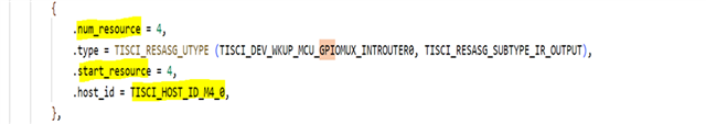
GPIO Interrupt Connectivity in AM62X SDK:

The SOC on the AM62 uses an interrupt router to route pin interrupts to the corresponding core for all GPIO pins. If you configure an interrupt for each pin, your design will be complicated.  Therefore, the routing concept is designed to minimize the overhead of all GPIO interrupts in the SOC. So, user can control bank interrupts and individual pin interrupts.

  • Procedure for GPIO Interrupt configuration

    GPIO Configuration: Configure the GPIO pin as an input from syscfg

    Destination Core Identification: Identify the destination core to route the GPIO interrupt to, which can be either the M4F, A53, or R5F.

    Interrupt Router Configuration: Configure the interrupt router output based on the destination core.

    Currently, this information is not configurable in the syscfg. So,you need to follow the procedure below to manually configure the interrupt router output.

    Enable the bank interrupt or individual pin interrupt, trigger type and interrupt number based on your requirements.

  • Configuring Interrupt Router Output manually

    Note: The Interrupt Router cannot be configured manually. It must be configured through the DMSC core. If you attempt to write to the Interrupt Router Register, the SOC will enter an exception state.

    Example: Configuring GPIO Interrupt for MCU_GPIO0_15 on M4FSS_0 Core

    Check the files "sciclient_defaultBoardcfg_rm.c" and "sciclient_irq_rm.c" in the following path:
    C:\ti\mcu_plus_sdk_am62x_08_05_00_14\source\drivers\sciclient\sciclient_default_boardcfg\am62x\sciclient_defaultBoardcfg_rm.c
    C:\ti\mcu_plus_sdk_am62x_08_05_00_14\source\drivers\sciclient\soc\am62x\sciclient_irq_rm.c

    1. In the above example, MCU_GPIO0_15 pin is selected for interrupt, and all interrupts of MCU_GPIO0 belong to TISCI_DEV_WKUP_MCU_GPIOMUX_INTROUTER0 router. The destination core is selected as M4FSS_0.


    2. TISCI_DEV_WKUP_MCU_GPIOMUX_INTROUTER0 can be selected from 0 to 12, but only 4 (num_resource) resources are allocated under the TISCI_DEV_WKUP_MCU_GPIOMUX_INTROUTER0 router in TISCI_HOST_ID_M4_0 core.

    3. Therefore, the Interrupt Router output can be set from 4 to 7, and the destination core is M4FSS_0.

  • Example: Configuring GPIO Interrupt for MCU_GPIO0_15 on M4FSS_0 core.

     Step 1:  Configure the GPIO pin as an input from syscfg

    Step 2: Configure GPIO Interrupt Router and select Destination core

    We need to configure four parameters in the Sciclient_gpioIrqSet(void) function:

    rmIrqReq.src_id , rmIrqReq.src_index , rmIrqReq.dst_id and rmIrqReq.dst_host_irq.

    In my example, I want to get an interrupt on MCU_GPIO0, so my source ID would be TISCI_DEV_WKUP_MCU_GPIOMUX_INTROUTER0:

    rmIrqReq.src_id = TISCI_DEV_WKUP_MCU_GPIOMUX_INTROUTER0;

    I want to generate an interrupt for Register Bank 0. According to the TRM, to get a bank interrupt on Bank 0, the source index would be 30. More details about the GPIO Interrupt source index can be found under chapter 10.1.6, "GPIO Interrupt Handling".

    rmIrqReq.src_index = 30U;

    As per the TRM from the above GPIO interrupt routing diagram, all MCU_GPIO interrupts are routed exclusively to the M4 domain and are not shared with any other cores. In this case, the destination ID would be the same as the source ID. However, if the interrupts are shared with other cores, the destination core must be specified.

    rmIrqReq.dst_id = TISCI_DEV_WKUP_MCU_GPIOMUX_INTROUTER0;

    The next step is to select the Interrupt Router Register from 0 to 12. I selected

    rmIrqReq.src_index to be 4U, 5U, 6U, or 7U based on the rm_c file.

    rmIrqReq.src_index = 4U;

    Step 3: Enable the trigger type , interrupt number and Bank Interrupt.

  • Note:

    1. This FAQ is mainly focused on routing the GPIO interrupt to the M4 core and is similar for routing to all other cores.
    2. If you want to enable the interrupt for each individual interrupt instead of bank interrupts, you must follow the steps below.

    In the following parameter, you must specify the pin number instead of the register bank number:

    1. src_index = Pin Index;