This thread has been locked.

If you have a related question, please click the "Ask a related question" button in the top right corner. The newly created question will be automatically linked to this question.

TDA4VM: How to configure the sensor information and generate specific dcc files

Part Number: TDA4VM

Hello TI:

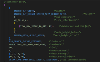
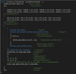
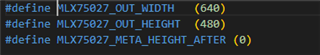
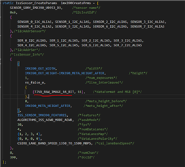
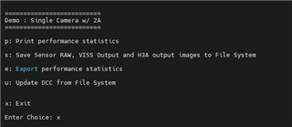
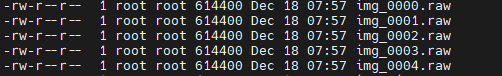
I have a Melexis 75027 TOF sensor which is not a RGB camera, the data format is RAW12, the width is 640, the height is 480. I reuse the sensor configuration based on IMX390, but change the width as 640, height as 480, meta height after as 1, format as TIVX_RAW_IMAGE_P12_BIT. But when I run the single camera, the software is stuck after log "ISS: Starting sensor [MLX75027-UB953_D3] ... !!!" and no image is on the screen. When I keep the weight, height as meta height as the same as IMX390, the software runs normally, although some disordered data comes on the screen. 

1.Could you help me to reconfigure the sensor information for the Melexis75027?

2. Another question is I reuse the dcc files from IMX390, but it seems not suitable for Melexis75027, is there any document to specify how to write the xml files and use the tool generate_dcc.sh to generate the dcc files for Melexis75027?

  • Hi Yi,

    Unfortunately, I am not familiar with sensor driver development or ToF sensors.

    To get you started, here is link for adding a new sensor driver to PSDK: https://software-dl.ti.com/jacinto7/esd/processor-sdk-rtos-jacinto7/latest/exports/docs/psdk_rtos/docs/user_guide/developer_notes_image_sensor.html

    How is your sensor/camera connected with TDA4?
    Do you have the same UB953/UB960 serdes pair as IMX390?

  • 1.I have already followed the instruction and passed the compilation.

    2. Yes, I have the same UB953/UB960 serdes pair as IMX390, and the UB960 is on the ADAS fusion board rev3 which is also provided by TI. Here is sensor configuration of struct IssSensor_CreateParams in each sensor driver file.  In the file, I need to configure the width, heigth, format, msb .etc. The width and heigth is 640x480 of TOF sensor, but after my configuration, the software runs stucked, and no error comes on the terminal. I cannot figure it out, I need help from TI.

    Second is how to get started to generate the dcc files for specific camera rather than reuse the dcc files from IMX390 because I think dcc files varies of different camera. I cannot find the description from the online docs.

  • I am not familiar with sensor/serdes and therefore I am copying for comments from his team.

    As I understand in general, UB953/UB960 parameters may not need to change much, but there are still camera module specific settings for UB953.
        https://git.ti.com/cgit/processor-sdk/imaging/tree/sensor_drv/src/imx390/imx390_serdes_config.h?h=main#n99
    You may check if any changes are needed for your sensor while referring to UB953 datasheet.

    Second is how to get started to generate the dcc files

    You have a ToF sensor with output in 12b raw pixels measuring distance.
    In this case, you probably don't really need to use VPAC-VISS to process the raw image.

    https://www.ti.com/lit/pdf/spracu7?keyMatch=ISP%20TUNING%20APP%20NOTE

  • Hello Guang hua,

    The demo of RGB sensor is not suitable for TOF sensor, the amplitude data and depth data of TOF sensor are calculated after getting the raw data from CSI interfaces.

    Which interface in the SDK is used to read the raw data from CSI interfaces(cam_CSIx_Dx_P,cam_CSIx_Dx_N) on the development board? I need to check if the raw data is correct from the sensor.

  • Hi Yi Wu,

    Did not get it, by interface, do you mean SW interface? There is a CSIRX node, which runs on R5F. You could probably have CSIRX output as Graph parameters, which most likely will be in all application, and then can map and access this buffer in the application space. 

    Regards,

    Brijesh

  • Hi Brijesh Jadav,

    Yes, I mean the SW interface.  Does this butter represent the raw data from CSIRX node? How can I get access this buffer in the application space?

  • Hi Yi Wu,

    After dequeueing the captured frame in the application, you can then map it in the application space and can get access to this buffer. Once you are done using this buffer, you can unmap the buffer and enqueue it back to the node.

    Regards,

    Brijesh

  • Hi Brijesh Jadav,

    If the width is 640, height is 480, and the data format is raw12, in my understanding, the raw data bytes should be 640*480*1.5 = 460800, but I found the raw data bytes of saved images are 614400 which is equal to 640*480*2.  Is my understanding incorrect? Could you give me some explanation?

  • Hi Yi Wu,

    Which SDK release are you using? I think RAW12 packed format was not supported in earlier release. Also if you are ok, can you please use raw12 pixel stored in 16bit container?

    Regards,

    Brijesh

  • ti-processor-sdk-rtos-j721e-evm-08_05_00_11 is used. After changing to raw16, the output is also 614400 bytes.

  • ok, this release does support raw12 in packed format. But raw16 should also work.. 

    What exactly do you want to do here? To map output buffer and analyze it?

    Regards,

    Brijesh

  • Yes, in order to check if the raw data of sensor from deserializer ub960 is correct.

    Why it is 640*480*2 =614400 instead of 640*480*1.5 = 460800 bytes raw data if I set raw12 for the pixel container? I attach the data format in 4 lane as below. How the pixel layout of the saved raw image if pixel container is set to TIVX_RAW_IMAGE_P12_BIT?

    another question: why the SW cannot exit, it is stuck here even if I enter 'x'?

  • Hi Yi Wu,

    This is not related to CSI2/MIPI. We need to check if CSIRX driver/Node is configured correctly for packed data.. Can you please tell me how you are checking the size of the image? 

    Also can you please check if you have below change in pdk/packages/ti/drv/csirx/src/csirx_drvUdma.c file? This is required for 12bit packed format. 

    + else if (chObj->chCfg->outFmt.ccsFormat == FVID2_CCSF_BITS12_PACKED)
    + {
    + chObj->dmaCfgParams.dataSizeShift =
    + (uint32_t)CSL_CSIRX_DMA_DATA_SIZE_SHIFT_8BITS;
    + }

    Regards,

    Brijesh

  • Hi BrijeshJadav,

    I check the bytes of saved raw image in /opt/vision/test_data/img_xxx.raw as below.

    In the pdk/packages/ti/drv/csirx/src/csirx_drvUdma.c file, the same code exists for the 12bit packed format.

  • Hi Yi Wu,

    That's probably because of the single camera application. The application assumes that the image is stored in unpacked format. Please check the API write_output_image_raw in ti-processor-sdk-rtos-j721e-evm-08_05_00_11\vision_apps\apps\basic_demos\app_single_cam\app_single_cam_common.c. In that num_bytes_per_pixel is fixed to 2, it does not check for storage format. Please change it to 1.5 or based on the image storage format, it would then store the images correctly.. 

    Regards,

    Brijesh

  • Hello Brijesh Jadav,

    I encounter another issue:

    According to the sensor 75027 datasheet, after I write the test pattern, the raw12 MIPI data of the first and second pixel data should be 0xFFE11D, translates into the first two pixels values 0xFFD (4093) and 0xE11 (3601)(see the screenshot as below), but the raw data in the saved image is 0xFD1FE1, it seems the recombining method is not as my expectation. Is there any configuration should be changed?

  • It looks like in 12-bit packed mode.

    FD, 1F, E1 --> FFD, E11

  • Hello Gang Hua,

    But the third byte should be the Pixel LSB of P2 and P1, the raw data should be 0xFF E1 1D not FD 1F E1. Is my understanding correct?

  • I am interpreting the data you received in DDR.

    It looks like little endian 12-bit packed.

    0xBA, 0xDC, 0xFE in DDR --> 0xCBA, 0xFED for the first 2 pixels