This thread has been locked.

If you have a related question, please click the "Ask a related question" button in the top right corner. The newly created question will be automatically linked to this question.

SK-AM62: SD Card boot problem and Rev.E3 EEPROM contents

Part Number: SK-AM62

Hi experts,

My customer is using SK-AM62(Rev.E3) to check the operation of the device, but it is no longer able to boot with SD card.

We believe it is because the customer has erased all the contents of the EEPROM, as described on P.33 of the "SK-AM62 Starter Kit User's Guide (Rev. A)".

Could you please share the contents of the EEPROM in Revision E3?
I only have EVM of Revision E2...

Also, could you tell me if there is anything else to check besides "use a different SD Card altogether"?
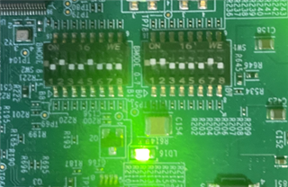
[Appendixl]
The configuration of Boot SWITC is based on the following URL.
https://dev.ti.com/tirex/explore/node?node=A__ADkBFm4ReTIZYz1OmNNnpA__linux_academy_am62x__XaWts8R__LATEST&search=am62

They are able to BOOT via UART, and they are able to Boot by reading the file system from SD after UART BOOT.
This time, they used "tisdk-default-image-am62xx-evm.wic.xz" from this SDK for the image.

Best regards,
O.H

  • Hi Mukul-san,

    Thank you for your reply.

    Based on the information you provided, they executed the following command to confirm that it is a GP device.
    However, they tried to create an image for GP with reference to "Linux Academy for AM62X - 2.2.Create a Linux Bootable SD Card", but it did not seem to work.

    Could you give me any other hints or points that we can check?
    We are now asking to try with SDK v8.5 and change another new SD card(SanDisk).

    $ python parse_uart_boot_socid.py <file-name.txt>
    
    -----------------------
    SoC ID Header Info:
    -----------------------
    ('NumBlocks            :', 1)
    -----------------------
    SoC ID Public ROM Info:
    -----------------------
    ('SubBlockId           :', 1)
    ('SubBlockSize         :', 26)
    ('DeviceName           :', 'am62x')
    ('DeviceType           :', 'GP  ')
    ('DMSC ROM Version     :', [0, 1, 0, 1])
    ('R5 ROM Version       :', [0, 1, 0, 1])

    Best regards,
    O.H

  • Hi Mukul-san,

    Thank you for your reply.

    We will share the information from the FAQ we received with the customer and will contact you again with the results.

    For your information, the customer was unable to boot using a different SD Card, even using SDK v8.5 or lower.

    We are now asking to try with SDK v8.5 and change another new SD card(SanDisk).

    Best regards,
    O.H

  • Hi O.H,

    When the customer wasn't able to boot SK-AM62 from SD card with SDK v8.5, does the serial console print any log message? If so, please share the log. If the serial console doesn't print any message, please share the picture of the sysboot switches of the board. I'd like to ensure it has been set properly for SD card boot.

    Please also note that when switching the boot mode from UART to SD card boot, you need to power cycle the board, as warm reset won't re-latch the sysboot settings.

  • Hi Bin Liu,

    Thank you for your reply.

    When the customer wasn't able to boot SK-AM62 from SD card with SDK v8.5, does the serial console print any log message? If so, please share the log. If the serial console doesn't print any message, please share the picture of the sysboot switches of the board. I'd like to ensure it has been set properly for SD card boot.

    The logs show nothing.
    Both states of the sysboot switch are tried in the figure below.

    Please also note that when switching the boot mode from UART to SD card boot, you need to power cycle the board, as warm reset won't re-latch the sysboot settings.

    I understood.

    Best regards,
    O.H

  • Hi O.H,

    I am unable to think of any other reason why the SD card boot doesn't print any message on the console. The boot mode switches setting is correct, and the SDK v8.5 prebuilt WIC image should boot E3 boards. I doubt the SD card has any issue since it is accessible in UART boot...

    Does the customer has another E3 to test?

    Do you have access to the customer's SD card to try boot on your E2 board?

  • We believe it is because the customer has erased all the contents of the EEPROM, as described on P.33 of the "SK-AM62 Starter Kit User's Guide (Rev. A)".

    Could you please share the contents of the EEPROM in Revision E3?
    I only have EVM of Revision E2...

    BTY, I don't think erasing EEPROM is causing the boot issue. Or at least ROM should load and execute the R5 SPL and print some messages on the UART console.

  • Hi Bin Liu,

    Thank you for your reply.

    Does the customer has another E3 to test?

    →No.

    Do you have access to the customer's SD card to try boot on your E2 board?

    →No, I do not have it on hand at the moment. I will consult with my customer.

    BTY, I don't think erasing EEPROM is causing the boot issue. Or at least ROM should load and execute the R5 SPL and print some messages on the UART console.

    →Could you tell me the contents of the EEPROM in E3 just to be sure?
    There was a some difference in contents of the EEPROM between E2 and E1.
    If you can't think of any other cause, I am thinking of trying it as a no-go...

    /* E1 */
    => i2c bus
    Bus 0:  i2c@20000000
    Bus 1:  i2c@20010000
       22: gpio@22, offset len 1, flags 0
    => i2c dev 0
    Setting bus to 0
    => i2c probe
    Valid chip addresses: 38 3F 51
    => i2c md 51 0.2 100
    0000: aa 55 33 ee 01 fc 00 10 2e 00 41 4d 36 32 2d 53    .U3.......AM62-S
    0010: 4b 45 56 4d 00 00 00 00 00 00 45 31 30 31 31 34    KEVM......E10114
    0020: 30 31 45 31 00 00 30 31 30 31 35 30 32 31 00 00    01E1..01015021..
    0030: 00 00 00 00 30 30 34 34 11 02 00 10 29 13 c2 00    ....0044....)...
    0040: 00 00 00 00 00 00 00 00 00 00 00 00 00 00 00 00    ................
    0050: 00 00 00 00 00 00 00 00 00 00 00 00 00 00 00 00    ................
    0060: 00 00 00 00 00 00 00 00 00 00 00 00 00 00 00 00    ................
    0070: 00 00 00 00 00 00 00 00 00 00 00 00 00 00 00 00    ................
    0080: 00 00 00 00 00 00 00 00 00 00 00 00 00 00 00 00    ................
    0090: 00 00 00 00 00 00 00 00 00 00 00 00 00 00 00 00    ................
    00a0: 00 00 00 00 00 00 00 00 00 00 00 00 00 00 00 00    ................
    00b0: 00 00 00 00 00 00 00 00 00 00 00 00 00 00 00 00    ................
    00c0: 00 00 00 00 00 00 00 00 00 00 00 00 00 00 00 00    ................
    00d0: 00 00 00 00 00 00 00 00 00 00 00 00 00 00 00 00    ................
    00e0: 00 00 00 00 00 00 00 00 00 00 00 00 00 00 00 00    ................
    00f0: 00 00 00 00 00 00 00 00 00 00 00 00 00 00 00 00    ................
    =>
    0100: 00 00 fe ff ff ff ff ff ff ff ff ff ff ff ff ff    ................
    0110: ff ff ff ff ff ff ff ff ff ff ff ff ff ff ff ff    ................
    0120: ff ff ff ff ff ff ff ff ff ff ff ff ff ff ff ff    ................
    0130: ff ff ff ff ff ff ff ff ff ff ff ff ff ff ff ff    ................
    0140: ff ff ff ff ff ff ff ff ff ff ff ff ff ff ff ff    ................
    0150: ff ff ff ff ff ff ff ff ff ff ff ff ff ff ff ff    ................
    0160: ff ff ff ff ff ff ff ff ff ff ff ff ff ff ff ff    ................
    0170: ff ff ff ff ff ff ff ff ff ff ff ff ff ff ff ff    ................
    0180: ff ff ff ff ff ff ff ff ff ff ff ff ff ff ff ff    ................
    0190: ff ff ff ff ff ff ff ff ff ff ff ff ff ff ff ff    ................
    01a0: ff ff ff ff ff ff ff ff ff ff ff ff ff ff ff ff    ................
    01b0: ff ff ff ff ff ff ff ff ff ff ff ff ff ff ff ff    ................
    01c0: ff ff ff ff ff ff ff ff ff ff ff ff ff ff ff ff    ................
    01d0: ff ff ff ff ff ff ff ff ff ff ff ff ff ff ff ff    ................
    01e0: ff ff ff ff ff ff ff ff ff ff ff ff ff ff ff ff    ................
    01f0: ff ff ff ff ff ff ff ff ff ff ff ff ff ff ff ff    ................
    /* E2 */
    => i2c bus
    Bus 0:  i2c@20000000
    Bus 1:  i2c@20010000
    
    => i2c dev 0
    Setting bus to 0
    => i2c probe
    Valid chip addresses: 38 3F 51
    => i2c md 51 0.2 100
    0000: aa 55 33 ee 01 fc 00 10 2e 00 41 4d 36 32 2d 53    .U3.......AM62-S
    0010: 4b 45 56 4d 00 00 00 00 00 00 45 32 30 31 31 34    KEVM......E20114
    0020: 30 31 45 32 00 00 30 31 30 31 31 38 32 32 00 00    01E2..01011822..
    0030: 00 00 00 00 30 30 32 35 11 02 00 10 29 13 c2 00    ....0025....)...
    0040: 00 00 70 ff 76 1e a3 52 00 00 00 00 00 00 00 00    ..p.v..R........
    0050: 00 00 00 00 00 00 00 00 00 00 00 00 00 00 00 00    ................
    0060: 00 00 00 00 00 00 00 00 00 00 00 00 00 00 00 00    ................
    0070: 00 00 00 00 00 00 00 00 00 00 00 00 00 00 00 00    ................
    0080: 00 00 00 00 00 00 00 00 00 00 00 00 00 00 00 00    ................
    0090: 00 00 00 00 00 00 00 00 00 00 00 00 00 00 00 00    ................
    00a0: 00 00 00 00 00 00 00 00 00 00 00 00 00 00 00 00    ................
    00b0: 00 00 00 00 00 00 00 00 00 00 00 00 00 00 00 00    ................
    00c0: 00 00 00 00 00 00 00 00 00 00 00 00 00 00 00 00    ................
    00d0: 00 00 00 00 00 00 00 00 00 00 00 00 00 00 00 00    ................
    00e0: 00 00 00 00 00 00 00 00 00 00 00 00 00 00 00 00    ................
    00f0: 00 00 00 00 00 00 00 00 00 00 00 00 00 00 00 00    ................
    =>
    0100: 00 00 fe ff ff ff ff ff ff ff ff ff ff ff ff ff    ................
    0110: ff ff ff ff ff ff ff ff ff ff ff ff ff ff ff ff    ................
    0120: ff ff ff ff ff ff ff ff ff ff ff ff ff ff ff ff    ................
    0130: ff ff ff ff ff ff ff ff ff ff ff ff ff ff ff ff    ................
    0140: ff ff ff ff ff ff ff ff ff ff ff ff ff ff ff ff    ................
    0150: ff ff ff ff ff ff ff ff ff ff ff ff ff ff ff ff    ................
    0160: ff ff ff ff ff ff ff ff ff ff ff ff ff ff ff ff    ................
    0170: ff ff ff ff ff ff ff ff ff ff ff ff ff ff ff ff    ................
    0180: ff ff ff ff ff ff ff ff ff ff ff ff ff ff ff ff    ................
    0190: ff ff ff ff ff ff ff ff ff ff ff ff ff ff ff ff    ................
    01a0: ff ff ff ff ff ff ff ff ff ff ff ff ff ff ff ff    ................
    01b0: ff ff ff ff ff ff ff ff ff ff ff ff ff ff ff ff    ................
    01c0: ff ff ff ff ff ff ff ff ff ff ff ff ff ff ff ff    ................
    01d0: ff ff ff ff ff ff ff ff ff ff ff ff ff ff ff ff    ................
    01e0: ff ff ff ff ff ff ff ff ff ff ff ff ff ff ff ff    ................
    01f0: ff ff ff ff ff ff ff ff ff ff ff ff ff ff ff ff    ................

    Best regards,
    O.H

  • Hi O.H,

    I don't have the EEPROM content handy, I would have to ask the hw team for it. But my point is that the boot loader prints some console messages before reading EEPROM. So this customer issue is not related to EEPROM.

    What tool does the customer used to flash the SDK 8.5 WIC image to the SD card? I use 'bmaptool' on Linux.

    I also want to double check the customer uses SDK 8.5 (or older) WIC image, not SDK8.6 WIC image, right?

  • Hi O.H,

    Please check the last post in the thread below, this customer had boot issue too that was due to admin privilege setting when using balenaEtcher on Windows. I am wondering if you have the same issue too.

    https://e2e.ti.com/support/processors-group/processors/f/processors-forum/1213142/sk-am62-unable-to-boot-sk-am62

  • Hi Bin Liu,

    Thank you for your reply.

    What tool does the customer used to flash the SDK 8.5 WIC image to the SD card? I use 'bmaptool' on Linux.

    They used "bmaptool" on Linux, but the result was the same. They originally used "balenaEtcher" on Windows.

    Currently, I am renting EVM version E2 to a customer. If no obvious problem can be found in comparison with version E2, we will offer to purchase a new EVM...

    I also want to double check the customer uses SDK 8.5 (or older) WIC image, not SDK8.6 WIC image, right?

    Yes. SDK v8.5(and older) tried.

    Best regards,
    O.H

  • Hi Bin Liu,

    We lent the customer an EVM and SD card that we had verified as bootable.
    As a result, we found that there was a problem with the customer's E3 EVM. It seems that Customer's E3 EVM is "unable to boot from SD only" using SDK v8.5.
    Could you give me some advice?

    [Summary of results]
    Our E2 EVM=EVM(A), Our SD Card=SD(A), Customer's E3 EVM=EVM(B), Customer's SD Card=SD(B)

    • EVM(A)+SD(A) → Successful boot
    • EVM(A)+SD(B) → Successful boot
    • EVM(B)+SD(A) → Unable to boot
    • EVM(B)+SD(B) → Unable to boot

    They also found that no matter what kind of data was in the E2PROM or OctalSPI (even if all the data was erased), EVM(A) was able to perform SD card boot.

    • The SD card is fine (because it boots up on the non-problematic EVM).
    • The firmware on the SD card is also fine (because it boots up with a fine EVM).
    • DIPSW setting is fine (because EVM without any problem starts up)
    • BootStrap reading seems to be fine (because it starts with OctalSPI and UART even with EVM(B)).
    • SD card can be read/write (EVM(B) can also read/write after starting up with OctalSPI or UART).
    • The contents of EEPROM are also irrelevant (even if the EEPROM of EVM(A) is erased, the device will start up).
    • The contents of OctalSPI flash does not matter either.(Even if the OctalSPI flash in EVM(A) is erased, the device will start up.)

    If you can confirm any other points, I would appreciate it if you could let me know.

    Best regards,
    O.H

  • Hi O.H,

    I cannot think of any other reason why the E3 doesn't boot from SD card.

    I am routing your query to our EVM team for comments.

  • Hello O.H,

    I read the below note 

    My customer is using SK-AM62(Rev.E3) to check the operation of the device, but it is no longer able to boot with SD card.

    Can you pls confirm if the E3 board was working and usable for some time before the issue was observed.

    Regards,

    Sreenivasa

  • Hello O.H,

    When the board boots fine with UART and doesn't boot on SD card, something wrong with the ROM boot or basic Linux bootloader. I have attached RTOS bootloader to try on your board. Please copy this image to your SD card (rename the existing tiboot3.bin and copy the attached file) and check if you are getting below log on the UART0 console?

    Starting NULL Bootloader ...

    DMSC Firmware Version 8.4.7--v08.04.07 (Jolly Jellyfi
    DMSC Firmware revision 0x8
    DMSC ABI revision 3.1

    INFO: Bootloader_runCpu:155: CPU m4f0-0 is initialized to 400000000 Hz !!!
    Some tests have failed!!
    INFO: Bootloader_JumpSelfCpu:226: All done, jumping self ...

    Regards,
    Senthil

    https://e2e.ti.com/cfs-file/__key/communityserver-discussions-components-files/791/3125.tiboot3.bin

  • Hi Sreenivasa,

    Thank you for your reply.

    Can you pls confirm if the E3 board was working and usable for some time before the issue was observed.

    EVM was working properly before.

    Best regards,
    O.H

  • Hi Senthil,

    Thank you for you reply.

    When the board boots fine with UART and doesn't boot on SD card, something wrong with the ROM boot or basic Linux bootloader. I have attached RTOS bootloader to try on your board. Please copy this image to your SD card (rename the existing tiboot3.bin and copy the attached file) and check if you are getting below log on the UART0 console?

    The results are as follows.

    Our E2 EVM=EVM(A), Customer's E3 EVM=EVM(B)

    • EVM(A) → Logs are displayed
    • EVM(B) → Logs are not displayed

    Best regards,
    O.H

  • Hello O.H, 

    Thank you.

    Can you pls confirm if the E3 board was working and usable for some time before the issue was observed.

    EVM was working properly before.

    From the hardware perspective, do you see any difference between the LEDs being ON for the E2 and the E3 board.

    Regards,

    Sreenivasa

  • Hello Sreenivasa,

    Thank you for your reply.

    From the hardware perspective, do you see any difference between the LEDs being ON for the E2 and the E3 board.

    The LED patterns are the same on the E2 and E3 boards when booted from the SD card (tiboot3.bin) as shown in the figure below.

    Best regards,
    O.H

  • Hello O.H, 

    Thank you for the inputs on the LED patterns.

    Let me check if senthil has some additional inputs.

    I will also check if the EEPROM being erased could be a cause of this behavior.

    Is customer able to read the EEPROM content from the E2 version board.

    Regards,

    Sreenivasa

  • Hello O.H,

    It seems SD boot settings might not be getting latched properly for some reason.

    Since the same board was working before, Can you confirm if there was any changes to the board or any specific software testing after which board started failing to boot from SD card? 

    Regards,
    Senthil

  • Hello Senthil,

    Thank you for your reply.

    Since the same board was working before, Can you confirm if there was any changes to the board or any specific software testing after which board started failing to boot from SD card? 

    What the customer has done is about the following

    • Change to board
      • Repeatedly switched DipSw between OSPI Boot and SD Boot to verify OSPI Boot.
      • No changes or modifications to Hardware.
    • Software
      • Delete all data in the existing partition (mtd*) of OSPI Flash, change the partition, and write the binary (tiboot3.bin, spl.bin, u-boot.img, etc.)
      • After deleting all the contents of EEPROM, write parameters used in customer programs.

    Best regards,
    O.H

  • Hello Sreenivasa,

    Thank you for your reply.

    I will also check if the EEPROM being erased could be a cause of this behavior.

    Is customer able to read the EEPROM content from the E2 version board.

    The original contents of the EEPROM on the E2 board are as follows.
    We do not know the current contents of the EEPROM on the E2 board, but they have succeeded in SD boot.

    /* E2 */
    => i2c bus
    Bus 0:  i2c@20000000
    Bus 1:  i2c@20010000
    
    => i2c dev 0
    Setting bus to 0
    => i2c probe
    Valid chip addresses: 38 3F 51
    => i2c md 51 0.2 100
    0000: aa 55 33 ee 01 fc 00 10 2e 00 41 4d 36 32 2d 53    .U3.......AM62-S
    0010: 4b 45 56 4d 00 00 00 00 00 00 45 32 30 31 31 34    KEVM......E20114
    0020: 30 31 45 32 00 00 30 31 30 31 31 38 32 32 00 00    01E2..01011822..
    0030: 00 00 00 00 30 30 32 35 11 02 00 10 29 13 c2 00    ....0025....)...
    0040: 00 00 70 ff 76 1e a3 52 00 00 00 00 00 00 00 00    ..p.v..R........
    0050: 00 00 00 00 00 00 00 00 00 00 00 00 00 00 00 00    ................
    0060: 00 00 00 00 00 00 00 00 00 00 00 00 00 00 00 00    ................
    0070: 00 00 00 00 00 00 00 00 00 00 00 00 00 00 00 00    ................
    0080: 00 00 00 00 00 00 00 00 00 00 00 00 00 00 00 00    ................
    0090: 00 00 00 00 00 00 00 00 00 00 00 00 00 00 00 00    ................
    00a0: 00 00 00 00 00 00 00 00 00 00 00 00 00 00 00 00    ................
    00b0: 00 00 00 00 00 00 00 00 00 00 00 00 00 00 00 00    ................
    00c0: 00 00 00 00 00 00 00 00 00 00 00 00 00 00 00 00    ................
    00d0: 00 00 00 00 00 00 00 00 00 00 00 00 00 00 00 00    ................
    00e0: 00 00 00 00 00 00 00 00 00 00 00 00 00 00 00 00    ................
    00f0: 00 00 00 00 00 00 00 00 00 00 00 00 00 00 00 00    ................
    =>
    0100: 00 00 fe ff ff ff ff ff ff ff ff ff ff ff ff ff    ................
    0110: ff ff ff ff ff ff ff ff ff ff ff ff ff ff ff ff    ................
    0120: ff ff ff ff ff ff ff ff ff ff ff ff ff ff ff ff    ................
    0130: ff ff ff ff ff ff ff ff ff ff ff ff ff ff ff ff    ................
    0140: ff ff ff ff ff ff ff ff ff ff ff ff ff ff ff ff    ................
    0150: ff ff ff ff ff ff ff ff ff ff ff ff ff ff ff ff    ................
    0160: ff ff ff ff ff ff ff ff ff ff ff ff ff ff ff ff    ................
    0170: ff ff ff ff ff ff ff ff ff ff ff ff ff ff ff ff    ................
    0180: ff ff ff ff ff ff ff ff ff ff ff ff ff ff ff ff    ................
    0190: ff ff ff ff ff ff ff ff ff ff ff ff ff ff ff ff    ................
    01a0: ff ff ff ff ff ff ff ff ff ff ff ff ff ff ff ff    ................
    01b0: ff ff ff ff ff ff ff ff ff ff ff ff ff ff ff ff    ................
    01c0: ff ff ff ff ff ff ff ff ff ff ff ff ff ff ff ff    ................
    01d0: ff ff ff ff ff ff ff ff ff ff ff ff ff ff ff ff    ................
    01e0: ff ff ff ff ff ff ff ff ff ff ff ff ff ff ff ff    ................
    01f0: ff ff ff ff ff ff ff ff ff ff ff ff ff ff ff ff    ................

    Best regards,
    O.H

  • Hello O.H,

    I believe some boot pins might have got stuck at one logic. We will try to get you boot switch diagnostic test on UART boot. I will update you.

    Regards,

    Senthil  

  • Hello O.H, 

    Adding to senthil's inputs 

    I understand that the UART boot should work irrespective of the EEPROM content.

    Would it be possible to probe the bootmode pins - to confirm the bootmode being set matches with the required bootmode.

    Regards,

    Sreenivasa

  • Hello Sreenivasa,

    Thank you for your reply.

    Would it be possible to probe the bootmode pins - to confirm the bootmode being set matches with the required bootmode.

    They had already checked the voltage, but the output voltage was as intended by the DIPSW.

    Best regards,
    O.H

  • Hello O.H, 

    Thank you.

    I assume you meant that the output was as expected.

    I would assume we may have to check the board functionality like power and clock.

    Is that something that could be done?

    Regards,

    Sreenivasa

  • Hello Senthil,

    We will try to get you boot switch diagnostic test on UART boot. I will update you.

    Sorry for rush you. Is there any update? 

    My customer is looking for answers and would appreciate it if you could tell me status.

    Best regards,
    O.H

  • Hello Sreenivasa,

    Thank you for your reply.

    I would assume we may have to check the board functionality like power and clock.

    Is that something that could be done?

    We will check with the customer and will contact you as soon as we have confirmation.

    Bestre gards,
    O.H

  • Hello O.H,

    Thank you for the note and appreciated.

    Regards,

    Sreenivasa

  • Hello Sreenivasa,

    I would assume we may have to check the board functionality like power and clock.

    Is that something that could be done?

    The confirmed results are listed below. There were no differences in power and clock inputs. The waveform is not shown, but it is both 25MHz and 1.8V.

    Voltage        
    Sl # Power Supply Test Point Voltage E3 E2
    1 VBUS_TYPEC1 C398.1 5V-15V    
    2 VBUS_TYPEC2 C415 5V-15V    
    3 VMAIN TP95 5V-15V 5.07 5.05
    4 VCC_5V0 TP70 5V 4.99 5
    5 VCC_3V3_SYS TP51 3.3V 3.32 3.33
    6 VDD_2V5 TP42 2.5V 2.49 2.47
    7 VPP_1V8 TP31 1.8V 0 0
    8 VDD_1V0 TP33 1.0V 0.98 0.99
    9 VDD_1V1 TP44 1.1V - -
    10 VDD_1V2 TP10 1.2V 1.19 1.19
    11 VDDA1V8 TP36 1.8V 1.79 1.78
    12 VCC_1V8 TP41 1.8V 1.79 1.79
    13 VDDSHV_SDIO TP29 1.8V/3.3V 3.29 3.28
    14 VCC1V2_DDR TP40 1.2V 1.18 1.2
    15 VCC_CORE TP45 0.85V 0.84 0.84
    16 VDD_CORE TP46 0.85V 0.84 0.84
    17 VCC_0V85 TP39 0.85V 0.84 0.84
    18 VDDR_CORE TP38 0.85V 0.84 0.84
    19 DDR_VREFCA TP43 0.6V 0.59 0.59
    20 VCC3V3_TA TP87 3.3V 3.29 3.3
    21 VCC3V3_XDS TP77 3.3V 0 0
    22 VCC_3V3_FT4232 C482.1 3.3V    

    Best regagds,
    O.H

  • Hello O.H,

    Thank you for the inputs.

    Let me review the inputs and comeback.

    Regards,

    Sreenivasa

  • Hello O.H,

    We are not able to integrate the boot switch diagnostics in UART boot. I also don't see any issue with the voltages you captured. So, I would recommend go ahead and submit RMA.

    Regards,
    Senthil

  • Helll Senthil, 

    Thank you.

    Can you pls confirm if the E3 board was working and usable for some time before the issue was observed.

    Hello O.H, any thoughts when these boards were purchased.

    Regards,

    Sreenivasa

  • Hello Senthil, Sreenivasa,

    Thank you for your advice.

    We are not able to integrate the boot switch diagnostics in UART boot. I also don't see any issue with the voltages you captured. So, I would recommend go ahead and submit RMA.

    Could you give us the contact information (email address or URL) to contact if we proceed with the RMA?

    Hello O.H, any thoughts when these boards were purchased.

    It is expected to be 2022/12. The exact timing is unknown as the customer made their own arrangements.

    Best regards,
    O.H

  • Hello O.H,

    Please refer to the attached customer return process.

    Regards,
    Senthil

    Customer Return Process - Hardware Applications - Confluence.pdf