This thread has been locked.

If you have a related question, please click the "Ask a related question" button in the top right corner. The newly created question will be automatically linked to this question.

PROCESSOR-SDK-AM62X: AM62x UDMA questions

Part Number: PROCESSOR-SDK-AM62X
Other Parts Discussed in Thread: SK-AM62

Hello,

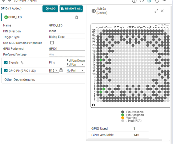
I have some questions about how the UDMA works and about the UDMA API provided by TI in the PSDK. My ultimate goal is to use DMA to transfer data from GPMC_DATA to RAM which gets kicked off by an interrupt from GPIO. I've studied and ran the qnx/examples/udma/udma_memcpy_test_qnx/src/udma_memcpy_test.c which works on our hardware with no modifications, but I have some questions:

  • In App_udmaTrpdInit I notice the example is using transfer record type 15, do you know why this type was used compared to transfer record type 11? Reading the reference manual I see the additional loops provides additional places for an event to stall the DMA transfer, but I don't see that happening in this example. What scenarios would software want to stall the transfer? Is there another reason to want to use multiple loops as shown in section 11.1.3.3.2.1.
  • I'm having trouble finding information about FMTFLAGS, can you point me to where in the reference manual this is described?
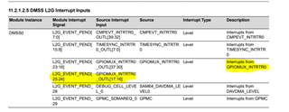
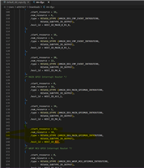
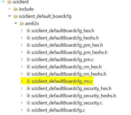
  • For interrupts, I want to check my understanding of how I should set up TISCI. I will use TISCI to set valid_parms to TISCI_MSG_VALUE_RM_IA_ID_VALID | TISCI_MSG_VALUE_RM_VINT_VALID | TISCI_MSG_VALUE_RM_GLOBAL_EVENT_VALID | TISCI_MSG_VALUE_RM_VINT_STATUS_BIT_INDEX_VALID as per the chart on the TISCI website here https://software-dl.ti.com/tisci/esd/latest/2_tisci_msgs/rm/rm_irq.html#pub-rm-irq-route-set. To understand what each of the various settings should be I referred to https://software-dl.ti.com/tisci/esd/latest/5_soc_doc/am62x/interrupt_cfg.html#interrupt-aggregator-device-ids.
    • ia_id should be 28
    • vint should be one of the IA VINT Index values that correspond to a GICSS0 destination since I'm using GPIO to trigger the interrupt
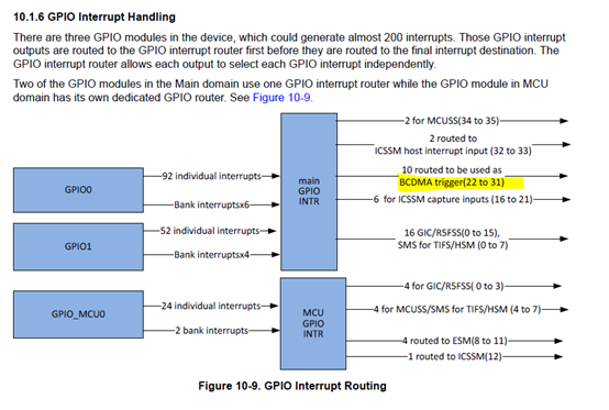
    • global_event - Can you confirm that this should be one of the BCDMA_0 Trigger indexes in the range of 50176 to 50339? Considering I want this interrupt to trigger a BCDMA this seems like the range.
    • vint_status_bit_index - Can you explain this field and how it's used?
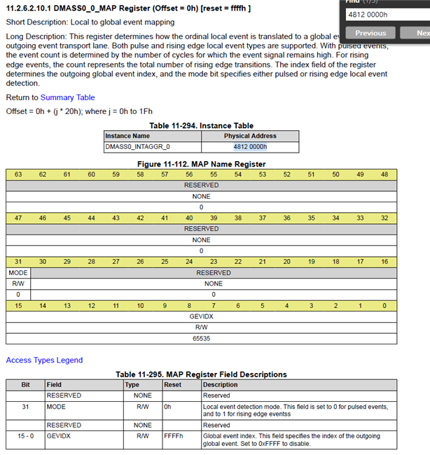
    • Once I use TISCI to configure the interrupt, I believe I need to modify the transfer request so it triggers on either on CSL_UDMAP_TR_FLAGS_TRIGGER_GLOBAL0 or CSL_UDMAP_TR_FLAGS_TRIGGER_GLOBAL1, can you explain the difference between these two triggers?
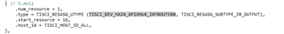
    • I believe that when I set up the UDMA events, I need to configure the eventType = UDMA_EVENT_TYPE_TR, make the event exclusive, and set vintrNum to the global_event I entered when configuring the interrupt. Can you confirm that my understanding is correct? Will I still be able to set the eventCb?
  • One more item, when I changed the source buffer from pointing to a virtual address in RAM to the virtual address that QNX maps the physical address of GPMC_DATA (0x50000000) and run the example, I see that the first 4 bytes are copied correctly, but the others do not. Is this a symptom of how the transfer record is set or do I need to refer to how the GPMC_CFG register is set up to configure the DMA?
    • Source Buffer virtual=0x3dd6985000(phys=0x50000000):

      src[0] = 0x50504502

      src[1] = 0x00

      src[2] = 0x9ECCFDBF

      src[3] = 0xFFFFFFFF

    • Destination Buffer virtual=0x3dd6984000(phys=0xbf06c000):

      dst[0] = 0x50504502

      dst[1] = 0x50505050

      dst[2] = 0x50505050

      dst[3] = 0x50505050

Thank you very much for your help!

From,

Daniel Fettke


  • Hi Dan,

    I have assigned the query to our expert. He will get back to you.

    Regards,

    Prashant

  • Dear Prashant,

    Thank you very much for forwarding my questions onto the expert. One other question that came up regarding setting up the transfer record in App_udmaTrpdInit. This function assigns a command ID of 0x25 to bit offset 16 of the transfer request flags field. According to the reference manual bits 16 through 23 are reserved for future use, can you explain if this command ID is used by the AM62x and if so does the reference manual reflect that? Also fmtflags field of the transfer request structure also seems to line up with a Reserved word according to Table 11-45 of the reference manual.

    From,

    Daniel Fettke

  • Dear Prashant,

    I've been studying the PDK code and would like to amend some of my original questions. I believe that I see now some fields of the TISCI_MSG_RM_IRQ_SET seem to get set after the UDMA event is registered. So when I create a UDMA event I think I should still use eventType = UDMA_EVENT_TYPE_TR but now I think it should be shared. After registering the event I should set up TISCI_MSG_RM_IRQ_SET for the following parameters if I want to initiate a transfer with a Main GPIO interrupt:

    valid_params = TISCI_MSG_VALUE_RM_IA_ID_VALID | TISCI_MSG_VALUE_RM_VINT_VALID | TISCI_MSG_VALUE_RM_GLOBAL_EVENT_VALID  | TISCI_MSG_VALUE_RM_VINT_STATUS_BIT_INDEX_VALID 

    src_id = 3

    src_index = 134 // GPIO1 Pin 44

    ia_id = 28 // From https://software-dl.ti.com/tisci/esd/latest/5_soc_doc/am62x/interrupt_cfg.html#interrupt-aggregator-device-ids

    vint = eventHandle->vintrNum

    global_event = eventHandle->globalEvent

    vint_status_bit_index = eventHandle->vintrBitNum

    Is this how I should set up the TISCI_MSG_RM_IRQ_SET command?

    I wanted to see what these values were after a completion event was created and this is what was printed to the console:

    globalEvent 13
    vintrNum 0xFFFF
    vintrBitNum 0
    irIntrNum 0xFFFF0000

    Does this look accurate to you? Looking here I see that the global event is in the range of SEVT, but should the vintrNum be one of the indexes in the Event-Based Interrupt SourceID?

    I was also wondering if there's a way to cause an error event based on a BCDMA channel, TX and/or RX error as shown in the Event-Based Interrupt Source IDs? Is that done with UDMA events like completion or teardown events or somewhere else?

    I see in udma_event.c that when a new UDMA interrupt event is created it is using src_id == srcIdRingIrq == devIdIa == 28. In the TISCI documentation I see 28 is assigned to be the Interrupt Aggregator Device Id, but I don't see it in the Interrupt Router Device IDs which is what I thought src_id was supposed to be. Are there more src_id's that aren't listed in this table? https://software-dl.ti.com/tisci/esd/latest/5_soc_doc/am62x/interrupt_cfg.html#interrupt-router-device-ids

    I'm looking forward to your expert's reply and discussing my questions further with your expert.

    From,

    Daniel Fettke

  • Hello Dan,

    Sorry for the delayed response. I understand that you want to trigger DMA based on the GPIO interrupt.

    AM62X supports auto-triggering DMA based on GPIO interrupts.

     And similarly, I have done in AM64X SOC. If you have a similar feature, then I can share my working code please check and do similar in QNX .

    Regards,

    S.Anil.

  • Hello Dan,

    I am checking your questions. Please give me some time so I can try to provide answers to all your questions.

    Regards,

    S.Anil.

  • Dear Anil,

    Thanks for taking a look at my questions. If you have an example for triggering DMA based transfers with a GPIO interrupt for the AM64X that you could share I would appreciate it if that's ok. Thanks again and I hope you have a great weekend.

    From,

    Dan Fettke

  • Hello Dan Fettke,

    Can you please find the software attached to trigger DMA based on a GPIO interrupt?

    You have to follow the steps below:

    1. Route GPIO interrupts to the GPIO interrupt router .

    2. Next, convert the local GPIO event into a global event.


    Please see TRM chapter 10 for more details.


    Software Changes : 

    1. Configure GPIO as an input based on your requirements.

    2. Enable GPIO Interrupt Routers 16 to 17 or 30 to 37. Since these routers only connected to L2G.

    Unfortunately, in the software, these routers are not configured.

    So, I have manually updated only the GPIO-16 router in the sciclient_defaultBoardcfg_rm.c file.

    Folder Path: C:timcu_plus_sdk_am64x_08_05_00_24sourcedriverssciclientsciclient_default_boardcfgam64x_am243x

    3. Compile the sciclient_defaultBoardcfg_rm.c file.

    You have to give the below command to compile it.

    4. Compile SBL and Flash SBL with updated board config file 

    5. Run your Application from CCS .

    Please let me know if you need any other help.

    NOTE: UDMA interrupts are not enabled in this example.

    3056.empty_am64x-evm_r5fss0-0_nortos_ti-arm-clang.zip

    Regards,

    S.Anil.

  • Dear Swargam,

    Thanks for your reply and example. After going through the example I think I understand now how Table 10-4 in the TRM is used to create a BCDMA interrupt with a GPIO input. I see that the AM62x has the DMASS0_INTAGGR_0 register from section 11.2.6.2.10.1 that seems to be similar to the screenshot you provided, but I'll have to find the AM64X TRM to compare. I do have a question about the secondary host, could you explain when a secondary host is required? Thanks again.

    From,

    Daniel Fettke

  • Hello Daniel Fettke,

    I do have a question about the secondary host, could you explain when a secondary host is required?

    Please don't use a secondary host, and it is not required in your application.

    You can pass below value in your application.

    rmIrqReq.secondary_host = TISCI_MSG_VALUE_RM_UNUSED_SECONDARY_HOST;

    Please let me know if you face problems making changes for AM62X.

    Regards,

    S.Anil.

  • Dear Swargam,

    Thanks for your guidance with the secondary host, could you explain though what scenarios it is used for? Or is it not used for the AM62x at all?

    I tried calling Sciclient_rmIrqSet with the following settings:

    rmIrqReq.valid_params  = TISCI_MSG_VALUE_RM_DST_ID_VALID |
                                                  TISCI_MSG_VALUE_RM_DST_HOST_IRQ_VALID;
    rmIrqReq.src_id              = 3U;
    rmIrqReq.src_index        = 135U;
    rmIrqReq.dst_id              = 28U;
    rmIrqReq.dst_host_irq    = 22U;
    but I got a NACK response back. I know my src_id and src_index are correct since I've used them for GIC interrupts. Based on your example dst_id should be 28 and that is the AM62X_DEV_DMASS0_INTAGGR_0 device ID according to https://software-dl.ti.com/tisci/esd/latest/5_soc_doc/am62x/devices.html. I've tried several dst_host_irq but still keep getting NACK responses with our custom hardware and with the SK-AM62. I do still have a question regarding a statement that I see here: https://software-dl.ti.com/tisci/esd/latest/5_soc_doc/am62x/interrupt_cfg.html#interrupt-router-device-ids that says " Based on AM62X Device IDs these are the valid Interrupt Router device IDs." and the following chart does not list device ID 28. I tried dst_id 3 as well as per the MAIN GPIO interrupt router output sources table but I was till getting NACK.
    From,
    Daniel Fettke 
  • Hello Dan,

    Can you please share your example UDMA project only and not include your application in it, and I will look at it and provide suggestions?

    Since I don't have access to QNX and am working on MCU+SDK, if I give answers based on MCU+SDK and they are not matching the QNX SDK, finally debugging will take more time.

    I need to check the rm-cfg files of your QNX project as well, since all resource allocation is done in this file, and this is the main file for routing GPIO interrupts to trigger DMA.

    Regards,

    S.Anil.

  • Hello Dan,

    1. Have you updated the rm-cfg file in your workspace?

    2. If not, please include the below-highlighted change in your rm-cfg.c file.


    3. Compile the rm-cfg file and use the command to compile the rm-cfg file -- > make a u-boot sysfw-image.

    4. Flash the updated SBL.

    5. In your application, try to configure the below changes.

    rmIrqReq.valid_params = 0U;
    rmIrqReq.valid_params |= TISCI_MSG_VALUE_RM_DST_ID_VALID;
    rmIrqReq.valid_params |= TISCI_MSG_VALUE_RM_DST_HOST_IRQ_VALID;
    rmIrqReq.global_event = 0U;
    rmIrqReq.src_id = TISCI_DEV_GPIO1;
    rmIrqReq.src_index = 45; //GPIO1_45 Pin 
    rmIrqReq.dst_id = TISCI_DEV_DMASS0_INTAGGR_0;
    rmIrqReq.dst_host_irq = 24 ;
    rmIrqReq.ia_id = 0U;
    rmIrqReq.vint = 0U;
    rmIrqReq.vint_status_bit_index = 0U;
    rmIrqReq.secondary_host = TISCI_MSG_VALUE_RM_UNUSED_SECONDARY_HOST;

    retVal = Sciclient_rmIrqSet(&rmIrqReq, &rmIrqResp, SystemP_WAIT_FOREVER);
    if(0 != retVal)
    {
    DebugP_log("[Error] Sciclient event config failed!!!\r\n");
    DebugP_assert(FALSE);
    }
    return;


    return retVal;

    6. Compile your Application and run it from CCS.


    If you make the above changes and it does not work out, I need to take help from the QNX person at our end and check further to see why it is not working.

    Regards,

    S.Anil.

  • Dear Swargam,

    What is the best way for me to get the modified TI PSDK udma_memcpy_test example and serial trace data to you? I don't think I can add files to this forum. Thanks.

    From,

    Daniel Fettke

  • Hello Daniel Fettke,

    Hello Dan,

    1. Have you updated the rm-cfg file in your workspace?

    2. If not, please include the below-highlighted change in your rm-cfg.c file.


    3. Compile the rm-cfg file and use the command to compile the rm-cfg file -- > make a u-boot sysfw-image.

    4. Flash the updated SBL.

    5. In your application, try to configure the below changes.

    rmIrqReq.valid_params = 0U;
    rmIrqReq.valid_params |= TISCI_MSG_VALUE_RM_DST_ID_VALID;
    rmIrqReq.valid_params |= TISCI_MSG_VALUE_RM_DST_HOST_IRQ_VALID;
    rmIrqReq.global_event = 0U;
    rmIrqReq.src_id = TISCI_DEV_GPIO1;
    rmIrqReq.src_index = 45; //GPIO1_45 Pin 
    rmIrqReq.dst_id = TISCI_DEV_DMASS0_INTAGGR_0;
    rmIrqReq.dst_host_irq = 24 ;
    rmIrqReq.ia_id = 0U;
    rmIrqReq.vint = 0U;
    rmIrqReq.vint_status_bit_index = 0U;
    rmIrqReq.secondary_host = TISCI_MSG_VALUE_RM_UNUSED_SECONDARY_HOST;

    retVal = Sciclient_rmIrqSet(&rmIrqReq, &rmIrqResp, SystemP_WAIT_FOREVER);
    if(0 != retVal)
    {
    DebugP_log("[Error] Sciclient event config failed!!!\r\n");
    DebugP_assert(FALSE);
    }
    return;


    return retVal;

    6. Compile your Application and run it from CCS.


    If you make the above changes and it does not work out, I need to take help from the QNX person at our end and check further to see why it is not working.

    Please follow the above steps at your end, and if it does not work out for the above method, I will have to work internally with QNX engineers since we are not experienced on QNX  side. 

    Please use the above method and report the results. Based on your results, we can proceed further.

    Regards,

    S.Anil

  • Dear Swargam,

    Sorry I don't see an rm-cfg.c file in the zip folder you attached above. Can you upload it and tell me where in the folder you attached I should copy it to? I also don't see a sysfw-image make target, is there an updated makefile I should use?

    From,

    Daniel Fettke

  • Hello  Daniel Fettke,

    Sorry I don't see an rm-cfg.c file in the zip folder you attached above.

    Sorry, I am not aware of your QNX folder structure, and I think the better thing is that I need to create example on our side and will share code with you.

     One more thing: typically, the DMSC architecture will be different in AM62X and AM64X.

    So, we can't guarantee that the same AM64X software will work in AM62X when configuring parameters through the SCI client.

    I have already sent mail to the QNX team, and I hope we both work together and try to share code with you.

    I will update the status once I receive mail from the QNX team.

    Typically, that file is available under the path below in MCU+SDK.

    C:\ti\mcu_plus_sdk_am64x_08_05_00_24\source\drivers\sciclient\sciclient_default_boardcfg\am64x_am243x

    Regards,

    S.Anil

  • Hello  Daniel Fettke,

    Still, the QNX team is busy with release activities.

    I have created the same example triggering DMA based on a GPIO interrupt on the AM62X R5F, and you can directly use the same application and integrate it into your application and it should work . Try to use QNX APIs rather than MCU+SDK APIs, and one more thing, you need to change the rm_cfg file, otherwise it does not work.

    I am attaching the below link to an update on the rm_cfg file on the Linux side, and I hope the same thing can be applicable for QNX.

    https://e2e.ti.com/support/processors-group/processors/f/processors-forum/1198105/faq-am64x-how-to-run-mcu-sdk-gpio_input_interrupt-example-for-r5fss0-0-with-linux-running-on-a53

    You have to follow the steps below:

    1. Route GPIO Events to the L2G .

    2. Next, convert the local GPIO event into a global event.


    Software Changes : 

    1. Configure GPIO as an input based on your requirements.

     In my example, I have configured GPIO1_23, which is available on EVM.

    2. Route the Main GPIO Interrupt Router outputs from 22 to 31 to L2G. Since these routers only connect to L2G.

    Please see the below image.

    Unfortunately, in the software, these routers are not routed to L2G.

    So, I have manually updated only the main GPIO router outputs from 22 to 31 in the sciclient_defaultBoardcfg_rm.c file.

    Folder Path: 

    C:\ti\mcu_plus_sdk_am62x_08_06_00_18\source\drivers\sciclient\sciclient_default_boardcfg\am62x


    3. Compile the sciclient_defaultBoardcfg_rm.c file by using below link.

    https://e2e.ti.com/support/processors-group/processors/f/processors-forum/1198105/faq-am64x-how-to-run-mcu-sdk-gpio_input_interrupt-example-for-r5fss0-0-with-linux-running-on-a53

    https://e2e.ti.com/support/processors-group/processors/f/processors-forum/1181741/am6442-how-r5-core-boot-as-processor-linux-sdk-then-load-mcu-plus-sdk-ccs-r5-demo/4490754#4490754

    4. To convert GPIO events to Global events, we need to configure the register below. 

    In the application, please check the below function for more details about converting a GPIO Event to a global event.


    static void configure_intaggrL2G (uint32_t localEvent, uint32_t globalEvent)
    {
    uint64_t eventRegOffset = CSL_DMASS0_INTAGGR_L2G_BASE + (localEvent * 0x20U);
    CSL_REG32_WR(eventRegOffset, (0U << 31U) | (globalEvent & 0xFFFFU) ); /* pulse event */
    }


    5. Compile SBL and Flash SBL with the updated board configuration file.

    6. Run your Application from CCS.


    Please let me know if you need any other help.

    The below link can be helpful to configure GPIO Routers and other Routers .

    https://software-dl.ti.com/tisci/esd/latest/5_soc_doc/am62x/interrupt_cfg.html

    For your requirement in the Software , you just need to update the below parameter in the function.


    rmIrqReq.src_index = 182U; //GPIO1_45 and Bank 2

    5001.udma_memcpy_interrupt_am62x-sk_r5fss0-0_freertos_ti-arm-clang.zip

    Regards,

    S.Anil.