Other Parts Discussed in Thread: SK-AM62
Hello,
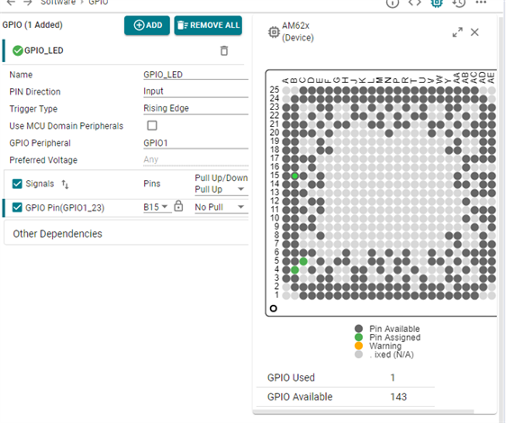
I have progressed further on this. Just to provide more detail on our implementation, our FPGA captures data from a number of A-D converters - frames of this data are then written into a FIFO in the FPGA, once a frame has been captured and stored in the FIFO, the FPGA raises a line which is connected to am62x GPIO1_15. The intention is to have this pin GPIO1_15 generate a DMA event in order to trigger a DMA transfer of data from the FIFO into a DMA buffer in the am62x's RAM.
Currently, on receiving this interrupt, in the kernel driver I simply copy the data from the FPGA's FIFO dword by dword into the RAM area allocated as DMA buffer, and this is working well, except that we would really like to use DMA to transfer this data without needing to do it in software.
The missing pieces of the puzzle at the moment are:
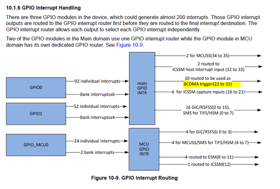
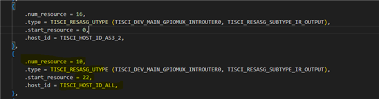
1. How do I configure the IRQ routing so that the GPIO1_15 line triggers a suitable DMA event to start the DMA transfer from this FPGA FIFO into the DMA buffer.
2. I attempted to configure the DMA engine to do the DMA transfer, and I believe I need to use a DMA_DEV_TO_MEM transfer type because we are reading repeatedly from the same address in the FPGA, however, when I attempt to configure the DMA channel using dmaengine_slave_config, it tells me that the channel I am using is only for MEM_TO_MEM DMA transfers. Is there any documentation which describes how I can set up DEV_TO_MEM transfers?
Thanks in advance
Hamish