This thread has been locked.

If you have a related question, please click the "Ask a related question" button in the top right corner. The newly created question will be automatically linked to this question.

SK-AM62: How to find PTP PPS pin on the EVK

Part Number: SK-AM62
Other Parts Discussed in Thread: AM625, AM623, AM625-Q1, AM620-Q1, SYSCONFIG

I have a SK-AM62 E3A

I am compiling my own custom yocto linux build using meta-ti.

meta-ti version: b86456651b1b9ce1e0612f9892387ec54b4f5759, tag: 09.00.00.004

linux version: 2b6f5746de558d954e42749b898fcdb4227dce5a, tag: 09.00.00.004

I am seeing this relevant commit message:

commit f608d07b036dee9529e93e49d7767b5affbf5353
Author: Siddharth Vadapalli <s-vadapalli@ti.com>
Date:   Mon May 29 10:00:03 2023 +0530

    arm64: dts: ti: k3-am625-sk: Add CPSW3G CPTS PPS support

And I am seeing these links:

    [0]
    Link: software-dl.ti.com/.../interrupt_cfg.html
    [1]
    Link: software-dl.ti.com/.../interrupt_cfg.html


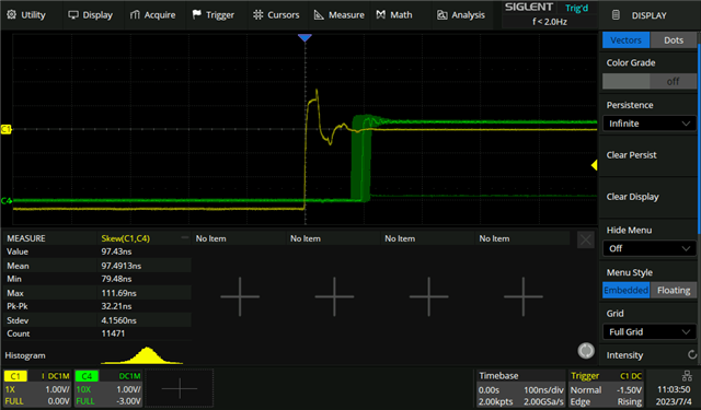
But I still cannot figure out what I can do to identify a specific pin that will output the PPS so that I can measure it.


Can someone help me understand what I can do?

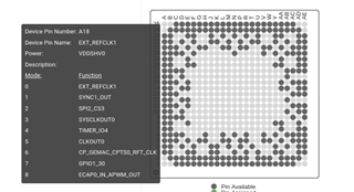
I have tried locating  cpts_hw3_push on the ti pinmux tool after selecting am62x device and alw package, but I can't find it.

  • Hello Xabier,

    First, please note that SDK 9.0 / Linux kernel 6.1 is still in development. The latest SDK release that I can support on these forums is SDK 8.6 (I expect SDK 9.0 to release sometime in about a month).

    Yes, we are finally upstreaming PPS support for CPSW ethernet on several of our processors starting with SDK 9.0, including AM62. The basic idea is that the CPTS within the CPSW outputs a signal from one of its GENF outputs, and that signal goes through the time sync router, and can be routed out to one of the SYNC_OUT pins.

    For more information about the time sync router in general, see this FAQ: https://e2e.ti.com/support/processors-group/processors/f/processors-forum/1061474/faq-am64x-what-is-the-time-sync-router-for-how-do-i-use-it? 

    Let's look at the latest version of that dts file you linked:

    https://git.ti.com/cgit/ti-linux-kernel/ti-linux-kernel/tree/arch/arm64/boot/dts/ti/k3-am625-sk.dts?h=ti-linux-6.1.y-cicd

    If you scroll down to the bottom of the file, you'll see a device tree node &timesync_router added to configure the time sync router to the desired output pin.

    Regards,

    Nick

  • Hello again Nick,

    Thank you very much for the highly detailed explanation. I have taken my time to try to understand all of it, but I still can't find my PPS out signal anywhere.

    I wonder if I'm doing something wrong, or if I'm just trying to use a feature that is still not functional.

    Let me describe what I have done so far, in case you can point out something I'm interpreting the wrong way.

    First, in the timesync_router that can be found in the dts file you link to, I see  this:

    /* pps [cpsw cpts genf1] in17 -> out12 [cpsw cpts hw3_push] */

    I still cannot locate hw3_push  anywhere on the am625 documentation, so I decided to look for SYNC_OUT pins, since you mention those in your explanation.

    Luckily, I was able to locate those in the AM62X Reference Manual (AM625, AM625-Q1, AM623, AM620-Q1 SPRSP58B – JUNE 2022 – REVISED JUNE 2023). If we go to page 56, 6.3.2.1 MAIN Domain, Table 6-6. CPTS Signal Descriptions, we see:

    SIGNAL NAME PIN TYPE DESCRIPTION ALW PIN AMC PIN
    SYNC0_OUT O CPTS Time Stamp Generator Bit 0 Output from Time Sync Router B16 E12
    SYNC1_OUT O CPTS Time Stamp Generator Bit 1 Output from Time Sync Router A18 C14
    SYNC2_OUT O CPTS Time Stamp Generator Bit 2 Output from Time Sync Router C15 B13
    SYNC3_OUT O CPTS Time Stamp Generator Bit 3 Output from Time Sync Router E15 A15

    If I'm not mistaken, I think the SK-AM62 rev E3A uses the ALW type AM625. If we cross reference these pins with the board schematics, we get these test points:

    SIGNAL NAME ALW CHIP PIN SK-AM62 E3A BOARD PIN
    SYNC0_OUT B16 J3.28
    SYNC1_OUT A18 J3.7
    SYNC2_OUT C15 J3.10
    SYNC3_OUT E15 J3.8

    I have my EVK directly connected via eth1 to a  PTP server running the automotive-master ptp profile using ptp4l 3.1.1.

    On my EVK, I am running the following commands on different consoles:

    am62xx-evm:~# ptp4l -m -f /usr/share/doc/linuxptp/configs/automotive-slave.cfg -i eth1 -p /dev/ptp0

    am62xx-evm:/usr/kernel-selftest/ptp# ./testptp /dev/ptp0 -P 1
    pps for system time request okay
    

    am62xx-evm:/usr/kernel-selftest/ptp# ppstest /dev/pps0
    trying PPS source "/dev/pps0"
    found PPS source "/dev/pps0"
    ok, found 1 source(s), now start fetching data...
    source 0 - assert 1294277998.000080399, sequence: 4231 - clear  0.000000000, sequence: 0
    source 0 - assert 1294277999.000080400, sequence: 4232 - clear  0.000000000, sequence: 0
    source 0 - assert 1294278000.000080399, sequence: 4233 - clear  0.000000000, sequence: 0
    source 0 - assert 1294278001.000080399, sequence: 4234 - clear  0.000000000, sequence: 0
    source 0 - assert 1294278002.000080398, sequence: 4235 - clear  0.000000000, sequence: 0
    

    But I still can't see anything resembling a PPS on any of the five pins I list above. Do you think I might be doing something wrong, or is there something not fully implemented yet?

  • Hello Xabier,

    I ran out of time to look through the June 2023 revision of the AM62x TRM today to see if we added a table with the outputs of the time sync router to that latest revision. The first thing I would check is to see what the time sync output 12 is.

    Regards,

    Nick

  • Ah, so do I need to wait for the June release of the TRM to be available?

    I have checked the november 2022 release  just in case, and Figure 10-8 (Page 7966 - Time Synchronization Support), and Table 10-8 (Page 7968 - Push event for CPSW) seem somehow related to all of this, but I still can't figure out how to map that to outputs, since the columns for this table are "Input Index" and "Interrupt Source".

  • Hello Xabier,

    Hmm, ok there has not been an updated TRM release yet. I am checking with the hardware team on when we can expect that, and on whether we can get some more information about the time sync router connections. Please ping the thread if I have not responded by Friday.

    I will check to see how the Linux developer tested the time sync on their board.

    Regards,

    Nick

  • Hello Xabier,

    Still following up on the hardware signal routing question. However, the Linux developer has provided a way to test PPS from the terminal in case this is helpful:

    "

    1. Request PPS signal generation by running:

    echo 1 > /sys/class/ptp/ptp0/pps_enable 

    2. Sample the PPS signal at 1 second interval and compare the timestamps to check if they truly are 1 second apart, by running the following commands:

    # Get first timestamp
    cat /sys/class/pps/pps0/assert
    # Wait for 1 second
    sleep 1
    # Get second timestamp
    cat /sys/class/pps/pps0/assert

    If the two timestamps are 1 second apart, that confirms the PPS signal.

    "

    Regards,

    Nick

  • Hello Nick,

    Thank you very much for all your help.

    I have tested these last commands, and it looks to me like everything looks fine:

    am62xx-evm:~# echo 1 > /sys/class/ptp/ptp0/pps_enable
    am62xx-evm:~# cat /sys/class/pps/pps0/assert ; sleep 1 ; cat /sys/class/pps/pps0/assert
    1294507007.000000015#55
    1294507008.000000014#56

  • Hello Xabier,

    I have added information about the TSR output signals in this new FAQ. Hope it helps:

    https://e2e.ti.com/support/processors-group/processors/f/processors-forum/1243869/faq-am62-what-is-the-time-sync-router-for-how-do-i-use-it

    Regards,

    Nick

  • Hello Xabier,

    One last update: We would actually NOT expect to see the PPS signal on one of the SYNCx_OUT pins, and that makes sense when we review the time sync router outputs on the FAQ I linked above.

    Time Sync Router output 12 goes to one of the CPSW CPTS inputs, called cpts_hw3_push. I am not sure why the developer chose this as their example mapping. I am following up with them separately.

    If you want the PPS signal to show up on a processor pin, you need to send it to a SYNCx_OUT signal (one of outputs 20-23), and make sure the pinmux settings are appropriately set for that pin.

    I do not have time to look at the AM62x SK EVM schematics today to see which SYNCx_OUT signals are routed to headers on the board that could be connected to an oscilloscope. However, if you run more tests and have any additional feedback, let me know and I will pass it along to the developer. Your timesync router mapping might make its way into our default EVM dts file.

    Regards,

    Nick

  • Hello Nick,

    Thank you very much for your help! I was actually working on a status update. It is now quite late for me and I haven't had the chance to test my progress today enough, but I have definitely been able to get some kind of output that resembles a PPS signal just before I had to leave the office.

    I'm not sure I will be able to post my process today, but I will give it a shot. If there's no new reply for me in the next few minutes, I hope to have something tomorrow.

  • Let me try to give a detailed description of the process I have followed to be able to the yet to be validated PPS output on my SK-AM62 E3A EVK.

    First, I have reviewed the (very useful) documentation provided by Nick here: https://e2e.ti.com/support/processors-group/processors/f/processors-forum/1243869/faq-am62-what-is-the-time-sync-router-for-how-do-i-use-it

    It looks like our best bet is to select one of the four SYNCx_OUT signals available on the chip. Like I said in one of my previous posts, I was able to locate those in the AM62X Reference Manual (AM625, AM625-Q1, AM623, AM620-Q1 SPRSP58B – JUNE 2022 – REVISED JUNE 2023). If we go to page 56, 6.3.2.1 MAIN Domain, Table 6-6. CPTS Signal Descriptions, we see:

    SIGNAL NAME DESCRIPTION ALW PIN
    SYNC0_OUT CPTS Time Stamp Generator Bit 0 Output from Time Sync Router B16
    SYNC1_OUT CPTS Time Stamp Generator Bit 1 Output from Time Sync Router A18
    SYNC2_OUT CPTS Time Stamp Generator Bit 2 Output from Time Sync Router C15
    SYNC3_OUT CPTS Time Stamp Generator Bit 3 Output from Time Sync Router E15

    The SK-AM62 rev E3A appears to be using the ALW type AM625. If we cross reference these pins with the board schematics, we get these test points:

    SIGNAL NAME ALW CHIP PIN SK-AM62 E3A BOARD PIN
    SYNC0_OUT B16 J3.28
    SYNC1_OUT A18 J3.7
    SYNC2_OUT C15 J3.10
    SYNC3_OUT E15 J3.8

    On my particular usecase, I'm already using J3.8 and J3.10 for other purposes, so I decided to go for J3.7, SYNC1_OUT, using ball/pin A18.

    Seeing the current k3-am625-sk.dts file, and according to your documentation, it looks like we need to add the following to that device tree file:

                    pinctrl-single,pins = <
                            /* pps [cpsw cpts genf1] in17 -> out12 [cpsw cpts hw3_push] */
                            K3_TS_OFFSET(12, 17)
    +                       /* pps [cpsw cpts genf1] in17 -> out21 [cpsw cpts SYNC1_OUT] */
    +                       K3_TS_OFFSET(21, 17)
                            >;
    

    I believe this takes care of the configuration of the TSR, and only that. Exactly like you say in your last post, what happens with chips that are as versatile as this one is that once you get your internals correctly configured you need to find the right pinmux configuration to be able to get your signals to the outside world.

    Now we need to figure out how to configure the pinmux. In order to do that, I have used your online tool SYSCONFIG IDE. Click on LAUNCH, and select the following:

    * SOFTWARE PRODUCT: MCU+ SDK for AM62x (08.06.00)

    * DEVICE: AM62x
    * PART: Default
    * Package ALW

    * Context: m4fss0-0

    Click on Start.

    Once in the SYSCONFIG IDE, Use the diagram on the lower-right part of the screen to locate ball A18:

    There we have almost all we need to complete the pinmux configuration. except for the physicall address of the ball. We can find that in the technical reference manual (SPRUIV7A – MAY 2022 – REVISED NOVEMBER 2022). If we search the ball by its name (EXT_REFCLK1), we will find that Table 6-2046. Pad Configuration Ball Names on page 3648 gives us what we want: F41F0h.

    With this, we can add the following code to the device tree file k3-am625-sk.dts:

    @@ AM62X_IOPAD(0x07c, PIN_OUTPUT, 7) /* (P25) GPMC0_CLK.GPIO0_31 */
                    >;
            };
     
    +       pps_pins_default: pps-pins-default {
    +               pinctrl-single,pins = <
    +                       AM62X_IOPAD(0x1F0, PIN_OUTPUT, 1) /* (A18) EXT_REFCLK1.SYNC1_OUT */
    +               >;
    +       };
    +
            main_gpio1_ioexp_intr_pins_default: main-gpio1-ioexp-intr-pins-default {
                    pinctrl-single,pins = <
    

    Once these modifications are compiled and built into a bootable image, all you need to do is fire up ptp4l with the desired configuration to get the phcs working, and run this command:

    am62xx-evm:/usr/kernel-selftest/ptp# ./testptp /dev/ptp0 -P 1

    I hope I didn't make any mistakes. I'll try to go over this and will get back to you to confirm, or make corrections.

    Thank you very much for your time and your help.

  • It all appears to be working correctly for now.

    I've had the system running for a litlle bit more than 3 hours at this point, and I have been collecting data from the generated signal. Using linuxptp v4.0 configured with the automotive profile on the SK-AM62 and a PC with an intel i210, this is what the syncrhonization looks like:

  • Hello Xabier,

    Awesome, glad that you got it working! Also, thank you for sharing your changes to the Linux devicetree. I have passed your example along to the developer, and we will add it to the default AM62x SK devicetree file.

    If you have any additional questions, feel free to make a new e2e thread and we will help you out there.

    Regards,

    Nick