This thread has been locked.

If you have a related question, please click the "Ask a related question" button in the top right corner. The newly created question will be automatically linked to this question.

TMDS64GPEVM: Set GPIO as output in device tree

Part Number: TMDS64GPEVM

Hello, 

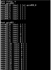
I am trying to configure some GPIOS of my EVM as inputs and outputs, whose state could be changed at runtime, therefore I think gpio-hog is not a solution because as far as I understand it prevents the gpio to be changed by the user space.However I have tried with and without the gpio-hog property but all the gpios are always set as inputs. I've also considered changing pullup-pulldown settings but it doesn't seem to change anything. So my question is, is it normal that by default the pins are all inpts ? If not, how could I set the direction from the device tree ? Thank you

Here is my setup : 

&main_pmx0 {
gpios_test_pins_default: gpios-test-pins-default {

		pinctrl-single,pins = <

			AM64X_IOPAD(0x0168, PIN_INPUT, 7) /* (U2) PRG0_PRU0_GPO2.GPIO1_2 */
			AM64X_IOPAD(0x016c, PIN_OUTPUT_PULLDOWN, 7) /* (V2) PRG0_PRU0_GPO3.GPIO1_3 */
			AM64X_IOPAD(0x0180, PIN_INPUT, 7) /* (T2) PRG0_PRU0_GPO8.GPIO1_8 */
			AM64X_IOPAD(0x01b4, PIN_OUTPUT, 7) /* (W2) PRG0_PRU1_GPO1.GPIO1_21 */
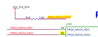
			AM64X_IOPAD(0x0200, PIN_OUTPUT, 7) /* (P2) PRG0_MDIO0_MDIO.GPIO1_40 */
			AM64X_IOPAD(0x0204, PIN_INPUT, 7) /* (P3) PRG0_MDIO0_MDC.GPIO1_41 */

		>;

	};
};

&main_gpio1 {

	pinctrl-names = "default";
	pinctrl-0 = <&gpios_test_pins_default>;
	status = "okay";
	gpio-line-names = "", "", "INT", "RESET", "", "", "", "",
	"TEST1", "", "", "", "", "", "", "", "", "", "", "", "",
	"WAKEUP", "", "", "", "", "", "", "", "", "", "", "", "", "", "", "", "", "", "", "TEST2", "TEST3";

	gpio_int {
	    gpios = <2 0>;
	    input;
	};

	gpio_reset {
	    gpios = <3 0>;
	    output-low;

	};

	gpio_wakeup {
	    gpio-hog;
	    gpios = <21 0>;
	    output-high;

	};

};
	

  • Hi Ines,

    I am currently looking into this. I am only aware of gpio-hog, so I am trying to see if there is any other possibilities. Please give me a few days to look at this.

    -Anshu

  • Hello Anshu,

    Thank you, I'm available in case you need more information.

  • Hi Ines,

    It seems to be normal that the default direction of a pin is input, but its important to understand what is means. PIN_INPUT means it enables the GPIO input buffer. The GPIO input buffer allows the pin to read the level driven from an external signal and read the level set by the application.  So having PIN_INPUT allows the pin to be used as an input and output depending on the direction set in userspace.

    Thank you to Bin Liu for clarifying this to me.

    -Anshu

  • Hello Anshu,

    Thanks for clarifying this! That's what I was thinking but I wasn't sure. As a matter of fact, when a pin is configured as an OUTPUT in the device tree (&main_pmx0 section), even if the userspace set the direction as input and connect it to a toggling signal of 0 - 3.3V, it will always read as 0. From your explanation I understand that the input buffer is not activated in that case. Do you know if there is a way to check the settings of the buffers ? I came accross "devmem2" but I'm not sure how to use it. 

    Thank you, 

  • Hi Ines,

    Of cause, you can use devmem2 to read the corresponding GPIO pin Pad Config register and check its RXACTIVE bit (bit 18) to see if the input receiver is enabled or not. But if the pinmux sets "PIN_INPUT" in device tree, the kernel driver ensure the input buffer is enabled - RXACTIVE bit is set.

  • Hi Bin, 

    Thank you for your answer. I made some tests and the output-high/ output-low property with the pullup/pulldown setup is not working properly for gpio1_40

    &main_pmx0 {
    gpios_test_pins_default: gpios-test-pins-default {
    
    		pinctrl-single,pins = <
    
    			
    			AM64X_IOPAD(0x016c, PIN_OUTPUT_PULLUP, 7) /* (V2) PRG0_PRU0_GPO3.GPIO1_3 */
    			AM64X_IOPAD(0x01b4, PIN_OUTPUT_PULLUP, 7) /* (W2) PRG0_PRU1_GPO1.GPIO1_21 */
    			AM64X_IOPAD(0x0200, PIN_OUTPUT_PULLDOWN, 7) /* (P2) PRG0_MDIO0_MDIO.GPIO1_40 */
    		
    		>;
    
    	};
    };
    &main_gpio1 {
    	pinctrl-names = "default";
    	pinctrl-0 = <&gpios2tsom_pins_default>;
    	status = "okay";
    
    
    	test1 {
    	    gpios = <3 0>;
    	    output-high;
    	};
    	test2 {
    	    gpios = <21 0>;
    	    output-high;
    	};
    	test3 {
    	    gpios = <40 0>;
    	    output-low;
    	};
    
    };

    I have a logic analyzer to check the pins. At boot, they all turn to output-high (not all at the same time though > DT= 6s, is it normal?) despite the output-low + pulldown config on gpio1_40. (Channel 1 is gpio1_40, channel 2 is gpio1_3 and channel 3 is gpio1_21)

    I have tested different inital state config (so either output-high + PULLUP or output-down + PULLDOWN) for the 3 outputs and noticed it's not working for the gpio1_40. I have seen that this pin is muxed with gmpc0_A12. Can that be a problem ? 

  • Hello,

    I looked at the schematics (PROC101C (004) sheet 27) and the gpio1_40 which is also PRG0_MDIO0_MDIO (P2) is directly connected to a 2.2K pull-up resistor 

     .

    This explains why the output-low + PULLDOWN config was not working. And maybe also why it was taking the high state as soon as the board was powered unlike the other gpios. With that pin being hard-wired like this, do you think there can be a turnaround to set it to outout low at boot ? 

    Thank you.

  • Hi Ines,

    Depending on what SDK version you are using, the process below may work. I was able to do this with SDK 9.0.

    A possible way is changing the pin configuration at the U-Boot prompt. Reboot your board and before autoboot occurs, hit any key to stop it. Then try running: gpio status -a . This should show the different GPIO pins available. Then try: gpio clear gpio@601000_40. This should set the pin GPIO1_40 to output and set the value to 0. You can try running 'gpio status -a' again to see the changes made.

    Here is more information about this: u-boot.readthedocs.io/.../gpio.html

    -Anshu

  • Hello Anshu,


    I have tried what you recommended but first I had to activate the gpio command in uboot (

    CONFIG_CMD_GPIO=y). When I run gpio status -a, only these two banks are displayed

    Nevertheless I tried to clear all these pins initially set to level 1 but it didn't change the gpio1_40 level so I assume the gpio1_40 is not one of these gpios.

    In the meantine I did some research to see how I can automate this and found out that I should set environment variable like this

    # setenv set-io 'gpio set <gpio-number>'

    # setenv bootcmd 'run set-io; run ubiboot; run sdboot'

    # saveenv

    The current value of bootcmd variable is

    bootcmd=run findfdt; run init_${boot}; run get_fit_${boot}; run get_overlaystring; run run_fit

    So I think I should do this instead :

    # setenv set-io 'gpio set <gpio-number>'

    # setenv bootcmd 'run set-io; run findfdt; run init_${boot}; run get_fit_${boot}; run get_overlaystring; run run_fit'

    # saveenv


    Regarding the SDK version, I'm unsure of the SDK version used, I have a yocto image based on dunfell that I customize to the needs of the project.

  • Hi Ines,

    After discussing internally, it is recommended to use an external pull down resistor to get the signal low prior to boot.

    -Anshu

  • Hello Anshu, 

    Thank you for your answer. So using u-boot is not a safe option ? I think it might be useful even for other GPIOs so could you help me understand why I don't have access to the gpios I set in the device tree? 

    For the external pull down resistor, that would be an option if we design a new card based on the AM6442, but with the EVM Ican't really apply this.

    Best regards,

  • Hi Ines,

    Using the U-boot prompt to interact with a GPIO pin is fine. Have you updated the U-Boot Device Tree to reflect the pins you added to the Linux Kernel Device Tree?

    -Anshu

  • Hello Anshu,

    I have updated the device tree file k3-am642-evm.dts located in arch/arm64/boot/dts/ti/. Is it the one you are talking of ? 

    Thank you

  • Hi Ines,

     It should be <U-boot folder>/arch/arm/dts for U-Boot. From there, modify the device tree to match the pins added to the Linux Kernel Device tree.

    -Anshu