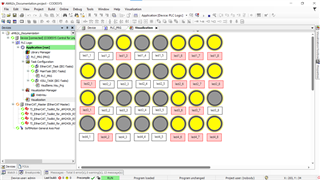
This FAQ walks the user through setting up an industrial networking EtherCAT system in CODESYS using an AM6xx MainDevice and one-or-more AM64x/AM243x SubDevice(s). Instructions are provided to set up MainDevice, SubDevice(s), and build the project & visualization in CODESYS Development System to control test LEDs on the SubDevice(s) from the MainDevice
Software versions tested in this documentation:
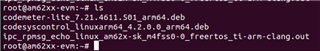
AM62x Processor SDK version: ti-processor-sdk-linux-rt-am62xx-evm-09.00.00.03 & ti-processor-sdk-linux-rt-am62xx-evm-08.06.00.45: https://www.ti.com/tool/PROCESSOR-SDK-AM62X#downloads
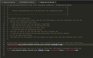
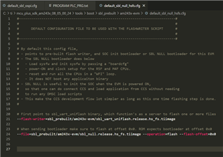
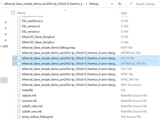
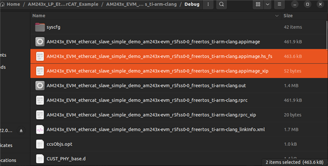
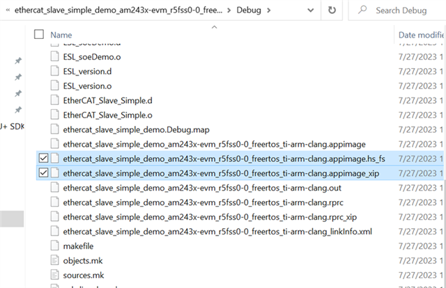
AM243x MCU+ SDK version: mcu_plus_sdk_am243x_08_05_00_24 (as of this writing, the AM243x-LP (HSFS) EtherCAT example demo does not work on MCU+ SDK 08_06. AM243x-EVM does not have this issue): https://www.ti.com/tool/download/MCU-PLUS-SDK-AM243X/08.05.00.24
Code Composer Studio version: Match CCS version to the version listed in the MCU+ SDK: https://software-dl.ti.com/mcu-plus-sdk/esd/AM243X/latest/exports/docs/api_guide_am243x/CCS_SETUP_PAGE.html#autotoc_md21
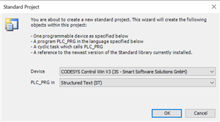
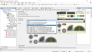
CODESYS Development System: CODESYS Development System V3 3.5.19.10:
(US store) https://us.store.codesys.com/codesys.html
(International store) https://store.codesys.com/en/
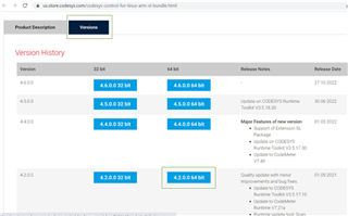
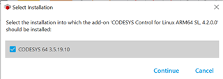
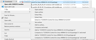
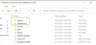
CODESYS Control for Linux ARM64 SL: CODESYS Control for Linux ARM64 SL 4.9.0.0.package & CODESYS Control for Linux ARM64 SL 4.2.0.0.package:
(US store) https://us.store.codesys.com/codesys-control-for-linux-arm-sl-bundle.html
(International store)
Old Link: https://store.codesys.com/en/codesys-control-for-linux-arm-sl-bundle.html
Updated Link: https://us.store.codesys.com/codesys-control-for-linux-arm-sl-1.html
System set up instructions overview (clickable links):
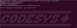
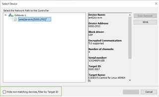
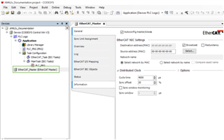
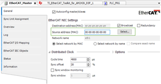
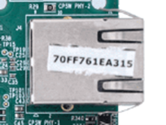
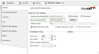
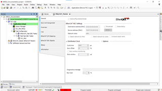
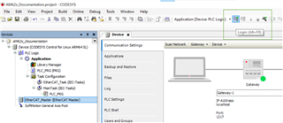
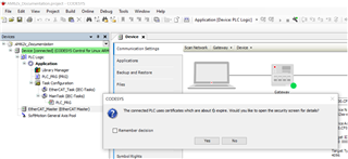
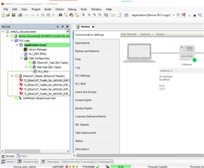
- Set up AM6xx EtherCAT MainDevice
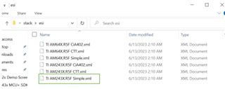
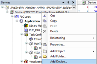
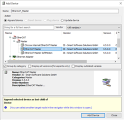
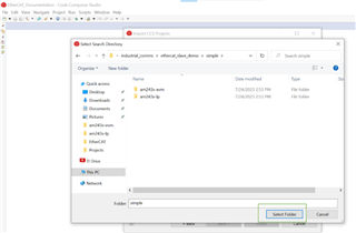
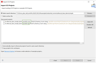
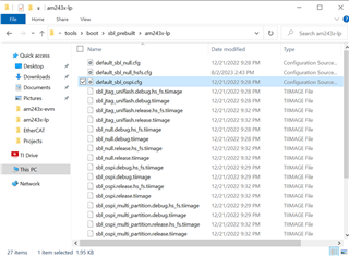
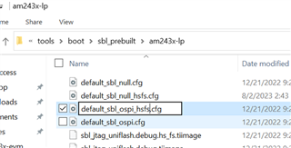
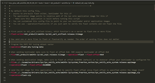
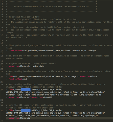
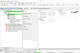
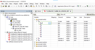
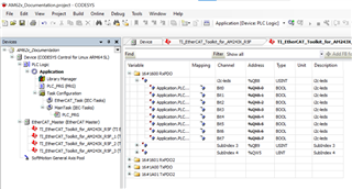
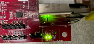
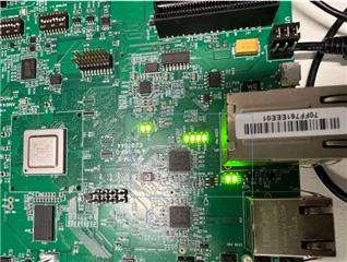
- Set up AM64x/AM243x EtherCAT SubDevice(s)
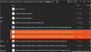
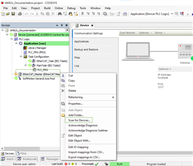
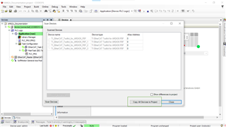
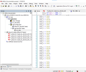
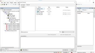
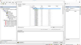
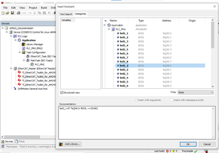
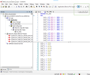
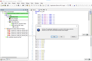
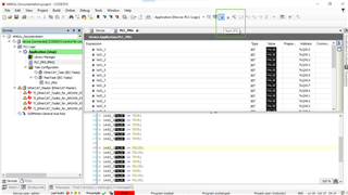
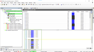
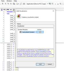
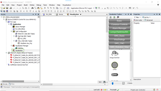
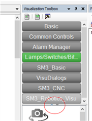
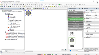
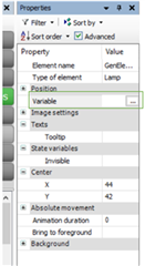
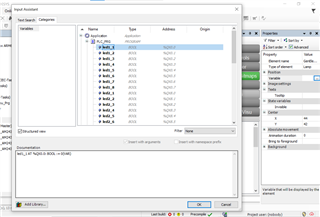
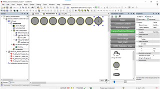
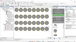
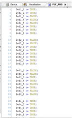
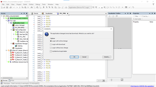
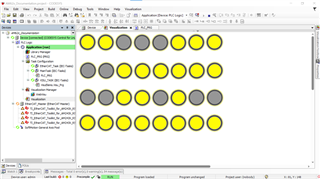
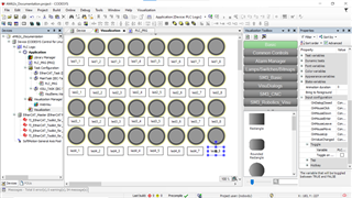
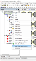
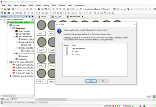
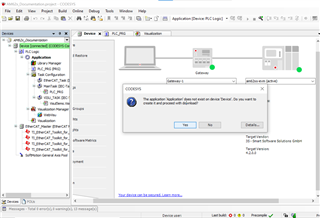
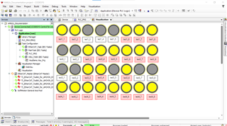
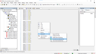
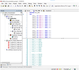
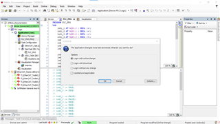
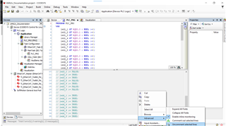
- Build project in CODESYS desktop software, build visualization, & test system