This thread has been locked.

If you have a related question, please click the "Ask a related question" button in the top right corner. The newly created question will be automatically linked to this question.

AM623: USB DFU bootmode/Discrete Power up

Part Number: AM623
Other Parts Discussed in Thread: SK-AM62

Hi TI team,

            We used TI's AM6234 in our project, but after SMT, we found that it was unable to burn through USB DFU; Fristly, we have adjusted the Bootmode to USB DFU mode, but the port cannot be read after power on. Where should we look for the reason? Can you provide your suggestion?

thank you~

  • Hi Dengke,

    What is "SMT"?

    What do you mean by "the port cannot be read after power on"?

  • The problem is: we hope to download through USB DFU, but after adjusting the bootmode pins (set to USB DFU mode), we cannot recognize the USB DFU port of AM6234 on the computer;

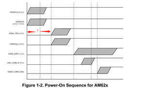
    We are using a separate power supply scheme and are currently checking the power supply timing. What we would like to know is whether there are specific requirements for the interval time between the occurrence of power rails? For example, the time interval between the occurrence of VDDSHV5 and VDDA_1P8

    Additionally, does AM6234 have some pin pins that must remain in a specific state to enter USB DFU mode?

    thank you\~

  • Hi Dengke,

    Can you switch to UART boot mode? Does the UART console print any character in UART boot mode?

  • Hi Liu Bin

    My phone number is 18183135801.

    Would you mind have more discusstions on the phone?

  • Hi Liu bin,

                     We are currently testing that the power supply of AM6234 can operate normally, but we are still unable to read the USB DFU port. There are several phenomena or issues that need your help to confirm, as follows:

    1. The crystal oscillator is currently not working properly. I saw in the power sequence section of the AM623 specification that the crystal oscillator will only start normally after the power supply is normal; Is it like this?

    2. We do not have power supply for VPP_1V8. I saw that VPP_1V8 is the 1.8V eFuse programming supply, I am not sure if it has any impact on this; And SOC_ VDDSHV5_ SDIO, we are currently using VCC_3V3_SYS to power it, do you know if it has any impact?

    3. I see three reset pins, all of which remain in the correct state before powering on; Are there any other pins that need to be in a specific state before being powered on?

    4. I see that in the power up sequence, the MCU_PORz will have a pull-up at the end. In the definition of the pin, it is an input pin. Currently, in our design, there is only a 4.7K pull-down. Do we need to pull it up at the appropriate time?


    We have tested the power supply timing using an oscilloscope. Can you help check it? As attached; The attachment also includes the schematic design of the TI part of our product, which we designed with reference to SK-AM62 PROC114E3_SCH; For your convenience in understanding, we also attach our power tree.

    Thank you~

    Ranger_TI PART_Schematic.pdfPower sequence.xlsxRanger_Power tree_0828.pdf

  • Update the Power sequence in attachment, please check.

    Compared to the power sequence of the development board, in our design, the rise time of VDDA_1V8 and VDD_2V5 is too long, and they have not yet fully risen to 1.8V, while VCC1V2_DDR has already reached 1.2V. Can this be the key reason?Power sequence.pdf

  • Hi Dengke,

    I see you are currently focusing on validating the board design, let me route your query to our hardware expert for comments.

  • Hello Dengke,

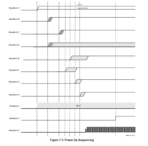
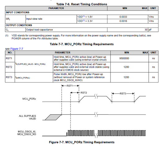
    if the Oscillator is not stable please check the below power sequence and the delay between power supply ramp and MCU_PORz high.

    If the MCU_PORx is being driven by an open drain output, a pullup is required and ensure the output is zero during supply ramp.

    I am not able to understand how you are configuring the bootmode. I see a 100K pulldown but not any pullup.

    Does the I2C expander drive the bootmode configuration?

    I am not able to locate the source of VSYS supply.

    Regards,

    Sreenivasa

  • Hello Dengke,

    I looked at the power-sequence diagram.

    I dont see the MCU_PORz timing captured after the last supply ramp.

    Please capture the MCU_PORz high timing with respect to the last supply ramp.

    Regards,'

    Sreenivasa

  • The oscillator should start within 9.5ms after all of the power supplies are valid. You are expected to hold reset low until the oscillator has started. Once all supplies are valid and the oscillator has started your reset circuit should release the device from reset by driving MCU_PORz high.

    Based on your comments above, your system has at least two problems. The first problem is the oscillator has not starting. This problem must be resolved first. The next problem is not having a reset circuit that is drives MCU_PORz high. The device will never come out of reset if the MCU_PORz pin remains low.

    Why are you creating a separate power source for VDDR_CORE. It appears you are operating VDD_CORE at 0.85V and the datasheet tells you to connect VDDR_CORE to the same source as VDD_CORE when VDD_CORE is operating at 0.85V. You only need to have a separate power source for VDDR_CORE when VDD_CORE is operating at 0.75V. This would eliminate any power sequencing concerns if you used a common 0.85V source for both.

    The device doesn't have any specific timing requirements between the power sequence ramps. The power sequencing requirements are only defined to prevent undesired potential differences between the power rails.

    Regards,
    Paul

  • Thank you~ I change the VDDR_CORE to the VCC_CORE power source, and pull up the MCU_PORz after all the power walid, then we can read the USB DFU port now. 

    But we are still unable to download, our software team is working with TI'software team, I hope it can be solved soon. I'll close this question.

    Thank you all. 

  • Hello Dengke,

    Thank you for the note.

    regards,

    Sreenivasa