This thread has been locked.

If you have a related question, please click the "Ask a related question" button in the top right corner. The newly created question will be automatically linked to this question.

[FAQ] AM625 / AM623 / AM620-Q1 / AM625-Q1 / AM625SIP : LFOSC usage in the processor

Part Number: AM625
Other Parts Discussed in Thread: AM62D-Q1, AM62P-Q1, , AM62A7-Q1, AM623, SYSCONFIG

Hi,

I have a question from my customer for LFOSC (external 32.668kHz).
According to datasheet section 7.11.4.1 Input Clocks / Oscillators, it seems the clock is optional.

• WKUP_LFOSC0_XO/WKUP_LFOSC0_XI — external crystal interface pins connected to internal lowfrequency
oscillator (WKUP_LFOSC0), which sources optional 32768 Hz reference clock.

If so, which functions / modules cannot be used in case LFOSC is not used?
TRM section 6.4.2.1 says follows. RTC and all Timers are impacted (all Timer modules in TRM section 12.7)?

• Low frequency oscillators
– LSOSC0_IN/LFOSC0_OUT - external 32.768KHz crystal interface pins of the internal oscillator which
sources a reference clock. Provides reference clock to RTC and Timers within MCU and MAIN domain.

Thanks and regards,
Koichiro Tashiro 

  • Hello Koichiro Tashiro 

    Thank you for the query.

    You will have to use the clock tree tool to understand the clock routing to peripherals.

    Let me check in parallel and come back.

    Regards,

    Sreenivasa

  • Any updates for this item?

  • Hello Koichiro Tashiro 

    Thank you for following-up.

    We do not expect many customers to use this clock source.
    However, some customers may decide to use this as a source for a real-time clock based on the accuracy requirements.

    Did you have a chance to explore the Clock Tree Tool?

    Regards,

    Sreenivasa

  • Hi Sreenivasa,

    Did you have a chance to explore the Clock Tree Tool?

    Yes, I checked it, but the Clock Tree Tool is not quite useful to check where the LFOSC is used.
    First of all there is no "LFOSC" in the tool. I guess it is called "RCOSC" in the tool.
    And it seems all Timers can use "RCOSC", but many other modules(McASPx, GPIOx, I2Cx, McSPIx, UARTx, etc.) can use it.
    So it is not possible to answer the customer's question from the tool.

    Thanks and regards,
    Koichiro Tashiro

  • Hello Koichiro Tashiro 

    Thank you.

    Please refer additional inputs that could help understand:

    None of the three supported reference clock frequencies or operating frequencies of the internal PLLs are able to produce a 32768 Hz clock with an integer divider. So it will not be possible to implement an accurate RTC inside our device using one of our timers without a more accurate clock source.
    All of the internal clock options will see significant drift relative to a true 32768 Hz clock.
    The customer will need to connect a 32768 Hz crystal to WKUP_LFOSC0 if they want to implement an internal RTC that does not have significant drift between updates from the host.
    Using an external RTC device may be a better option for most customers and will definitely be a better option if they need an RTC with battery backup.

    The connection of 32K is use case dependent and based on the performance requirement an external LFOSC can be used.

    Regards,

    Sreenivasa

  • Hi Sreenivasa,

    Thanks for clarification.
    I understood LFOSC is needed to use accurate RTC function inside SoC.
    Otherwise, LFOSC is an optional.

    Thanks and regards,
    Koichiro Tashiro

  • Hello Koichiro Tashiro 

    Thank you and Your understanding is correct.

    Regards,

    Sreenivasa

  • Hello Koichiro Tashiro 

    Here are some guidelines and recommendations for using the LFOSC

    Otherwise, LFOSC is an optional.

    7.11.4.1.3 WKUP_LFOSC0 Internal Oscillator Clock Source

    When WKUP_LFOSC0 is used, follow the below section for clock implementation.

    Refer the below figure for he recommended crystal circuit.

    Figure 7-21. WKUP_LFOSC0 Crystal Implementation

    Table 7-24. WKUP_LFOSC0 Crystal Electrical Characteristics

    7.11.4.1.4 WKUP_LFOSC0 LVCMOS Digital Clock Source

    When not used refer below section for connecting the SoC LFOSC0 pins 

    7.11.4.1.5 WKUP_LFOSC0 Not Used

    Note: it is recommended to provide provision to ground WKUP_LFOSC0_XI input and WKUP_LFOSC0_XO output through a 0R for future enhancements.

    Regards,

    Sreenivasa 

  • Hi Sreenivasa,

    Thanks for updates.

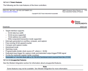
    The customer found below description in TRM section 12.7.4.4.5.1 1-ms Tick Generation.


    Other than accurate RTC, 1-ms tick generation is not possible without LFOSC, correct?

    Thanks and regards,
    Koichiro Tashiro
  • Hello Koichiro Tashiro 

    Please refer below. I guess the 1-ms tick is for the RTC as described below.

    The only available source for a 32.768-kHz clock is the LFOSC. The HFOSC is not capable of
    generating a true 32.788-kHz frequency.

    Regards,

    Sreenivasa

  • Hello Koichiro Tashiro 

    Pls let me know if you have any additional query or if i can close the thread.

    LFOSC0 clock is optional.  The system configuration/uses cases will dictate if the low freq clock is required, but the processor can operate without it.

    Regards,

    Sreenivasa

  • Hi Sreenivasa,

    I have one more question. There are other 32k clk sources called "CLK_32K_RC" and "HFOSC0_CLKOUT_32K" in the device.
    I think these frequency is not accurate enough, but still usable as 32k source?

    Thanks and regards,
    Koichiro Tashiro

  • Hello Koichiro Tashiro 

    Thank you.

    have one more question. There are other 32k clk sources called "CLK_32K_RC" and "HFOSC0_CLKOUT_32K" in the device.
    I think these frequency is not accurate enough, but still usable as 32k source?

    Correct.

    The RC could also have wide variation over the temperature.

    Regards,

    Sreenivasa

  • Hi Board designers,

    MCU_OSC0_XO and WKUP_LFOSC0_XO pins are recommended to connect to ground as per data sheet figure 6-20 and 6-24. But our customer made them open for their design and is asking if there is any risk to keep it open. Please let us know if the customer can keep it open or connecting them to ground is hard requirement.


    Are MCU_OSC0 and WKUP_LFOSC0 receiving a LVCMOS clock input? If yes, please follow the datasheet requirement to ground the *_XO pins. The *_XI and *_XO pins are capacitively coupled as differential signals to drive the respective OSC clock into the device. Connecting *_XO to VSS makes the receiver act a single-ended comparator.

    In the event WKUP_LFOSC0 is not being used, Figure 6-25 in the datasheet reveals WKUP_LFOSC0_XI should be grounded and WKUP_LFOSC0_XO can be left NC/open.


    The customer is already designed and fabricated the board with oscillator connected to MCU_OSC0_XI/WKUP_LFOSC0_XI and MCU_OSC0_XO/WKUP_LFOSC0_XO are open. So, depending on your answer, customer has to make a decision to rework the board or not.
    XO pins must be connected to VSS if XI is used? or any chance to keep XO pins open even though XI is uased?

    TI recommends following the datasheet guidance to minimize noise on the differential receiver. We cannot guarantee the performance for the oscillator outside datasheet guidelines, and that configuration has not been validated by TI. There is a chance it could work with *_XO left open but we would not recommend going to production with that.

    Regards,

    Sreenivasa

  • Hi Board designers,

    AM62D-Q1: Can we remove WKUP DOMAIN circuit?

    No issues removing the 32K crystal and associated components.
    Please note that there are connection requirements to be followed.
    Xi is required to be connected to ground.
    Please refer Am62A datat sheet section
    7.10.4.1.5 WKUP_LFOSC0 Not Used
    Figure 7-25 shows the recommended oscillator connections when WKUP_LFOSC0 is not used.

    +) AM62A7-Q1: schematic review RTC - Processors forum - Processors - TI E2E support forums

    AM62P-Q1: Clock Accuracy

    The clocks inside AM62Px are derived from the reference clock connected to MCU_OSC0 and/or WKUP_LFOSC0. You must connect a 25MHz reference clock to MCU_OSC0. Connecting a 32.768kHz reference clock to WKUP_LFOSC0 is optional.

    You should use clock tree tool provided in the SYSCONGIG tool to help develop a better understand the AM62Px clocking topology.

    LFOSC0 load capacitance

    The load capacitance range of the crystal will be half of the recommended capacitor value range since there are connected in series with the crystals resonate circuit.

    • For the 32kHz XTAL requirement, is it correct to understand that the XTAL has a minimum load capacitance of 6 pF and a maximum value of 12 pF?

      This is correct.

      Regards,

      Sreenivasa

  • Hi Board Designers, 

    AM625: AM625: RTC(WKUP_LFOSC0) is low voltage(Continued)

    https://e2e.ti.com/support/processors-group/processors/f/processors-forum/1273452/am625-am625-rtc-wkup_lfosc0-is-low-voltage-continued/4830820

    AM62A7-Q1: Use of WKUP_LFOSC0

    https://e2e.ti.com/support/processors-group/processors/f/processors-forum/1262394/am62a7-q1-use-of-wkup_lfosc0

    AM623: CLK_32K_RC accuracy specifications

    https://e2e.ti.com/support/processors-group/processors/f/processors-forum/1252849/am623-clk_32k_rc-accuracy-specifications/4741773

    AM625: LFOSC0 not starting at cold temperatures.

    https://e2e.ti.com/support/processors-group/processors/f/processors-forum/1184386/am625-lfosc0-not-starting-at-cold-temperatures/4460574

    https://e2e.ti.com/support/processors-group/processors/f/processors-forum/1123440/am625-regarding-am6254/4166787

    1) AM62x provides a several optional clock inputs, WKUP_LFOSC0, AUDIO_EXT_REFCLK[1:0], EXT_REFCLK1, and MCU_EXT_REFCLK0. You should search the device TRM for each clock input to understand which internal modules can be clocked form each of these optional clock inputs. Then you need to determine if your specific system implementation is able to use one of the internal clock references or requires a external clock.

    2) The internal 32k clock is generated from a integer divider of HFOSC operating frequency, which only supports 24 MHz , 25 MHz, or 26 MHz. For example, If HFOSC = 25 MHz, the internal 32k clock will be (25000000/95)/8= 32,894.7368 Hz or (25000000/96)/8= 32,552.0833 Hz. You may need to use WKUP_LFOSC0 if your application requires the internal 32k clock to be exactly 32,768 Hz.

    3) Backup boot mode is only executed if primary boot mode fails. The boot mode/sequence selected depends on your specific system requirements. Please refer to the Initialization chapter in the device TRM for more details

    https://e2e.ti.com/support/processors-group/processors/f/processors-forum/1123363/am625-regarding-clock-inputs-for-main-domain

    We are using AM6254 in our design.

    We want to understand the use of these optional signals i.e. MCU_Ext_REFCLK0, EXT_REFCLK. Currently we have provided clock inputs on MCU_OSC pins(25MHz) and on the WKUP_LFOSC0(32.768KHz).We want to understand further if these MCU_Ext_REFCLK0, EXT_REFCLK pins can be excluded.

    These are optional clock inputs. You can search the AM62x TRM for these names and it will show you all modules which can be clocked from these inputs. 

    You will need to determine if a separate reference clock is required for these modules based on your specific system implementation.

    Your system may be able to use internal clocking options for each of these modules. If so, external clock sources will not be required for these inputs.

    AM623: How to enable Low-Frequency Oscillator with External Crystal?

    https://e2e.ti.com/support/processors-group/processors/f/processors-forum/1331335/am623-how-to-enable-low-frequency-oscillator-with-external-crystal/5068239

    AM625: RTC(WKUP_LFOSC0) is low voltage
    https://e2e.ti.com/support/processors-group/processors/f/processors-forum/1247605/am625-rtc-wkup_lfosc0-is-low-voltage

    AM625: AM625: RTC(WKUP_LFOSC0) is low voltage (Continued)

    https://e2e.ti.com/support/processors-group/processors/f/processors-forum/1273452/am625-am625-rtc-wkup_lfosc0-is-low-voltage-continued/4830820

    (+) [FAQ] AM625: Crystal drive strength specifications - Processors forum - Processors - TI E2E support forums

    Based on your follow-up for additional info please refer the inputs i received from the device expert.

    The crystal power dissipation will depend on the crystal they select and the crystal circuit (including the load capacitance) they implement. Our oscillator has an AGC that monitors oscillation of the crystal circuit and adjusts its gain to maintain oscillation. Therefore, it doesn’t have fixed drive strength.
    Even if we told them our max drive strength, the power dissipation in the crystal would still depend on the crystal they select and the crystal circuit (including the load capacitance) they implement.
    The formula for calculating crystal power dissipation in the crystal: Pxtal = 0.5 ESR (2 π Fxtal CL Vxtal).
    Our oscillator could drive a voltage that approaches the potential of oscillator power supply. This is not very likely to occur with most crystal implementations. As you can see in the formula, the crystal power dissipation is still dependent on the ESR of the crystal circuit even if you assume a worst case value of 1.8V for Vxtal. Using a worst case value of 1.8V for Vxtal is very unrealistic for a typical crystal implementation since Vxtal is more likely to be 1.0V than 1.8V.

    Additional inputs 

    I have a query on the WKUP_CLKOUT0 use case Many customer use the pin to source clock to RF or WiFi modules – 32.768K
    WKUP_CLKOUT0 defaults to 25M clock output
    I am telling customers to ensure the reset is released only after the WKUP_CLKOUT0 is set to 32K
    Did you have any thoughts or concerns or recommendations on the customers use case.

    You need to confirm what the RF or WiFi modulese will do if you source a 25MHz clock into the 32.768kHz input, even when held in reset.

    I would hope it is able to ignore this clock in such a way that it doesn’t create a problem as long as you wait and take nSHUTD high after the correct source has been selected, but that may not be the case. I would ask the team that supports RF or WiFi modules if I were designing this system.

    As an example the CC256x device requires the slow clock frequency to be 32.768 kHz ±250 ppm. I’m not sure our 32k output is able to meet this requirement.

    I spent some time looking at the WKUP_CLKOUT0 sources and determined the internal clock named “DEVICE_CLKOUT_32K”, which I assume is the one the customer plans to select for WKUP_CLKOUT0, can be sourced from one of three possible clock sources. The three sources are HFOSC_CLKOUT_32K, CLK_32K_RC, and LFOSC0_CLKOUT. The only one of these three that will be accurate enough for the TI CC256x device is LFOSC0_CLK, which means they must connect a 32.768kHz crystal circuit to the AM62x low frequency oscillator. However, it appears they are not planning to install the 32.768kHz crystal circuit components. If so, they would need to use one of the other two sources.

    HFOSC_CLKOUT_32K is a integer divider of the HFOSC reference frequency. The closest you can get to 32.768kHz is 32.89474kHz with a divider of 760, or 32.55208kHz with a divider of 768. Note: The frequency error would be 126.74Hz or 3868 PPM at 32.89474kHz, which is over 15x the limit of 250 PPM.

    The CLK_32K_RC would be even worse than HFOSC_CLKOUT_32K.

    https://e2e.ti.com/support/processors-group/processors/f/processors-forum/1262394/am62a7-q1-use-of-wkup_lfosc0

    Internally generated 32 kHz clock sources are not as accurate as WKUP_LFOSC0. The customer should use the clock tree tool function in the SYSCONFIG tool to understand which internal functions could benefit from a more accurate 32 kHz clock. They would need to decide if their use case requires any of these functions to be clocked from a more accurate 32.768 kHz source.

    Note: the SYSCONFIG tool can be found under Design & Development / Software Development in the AM62Ax product folder on ti.com.

     AM62P-Q1: Clock Accuracy 

     RE: AM625: Regarding AM6254 

    1) AM62x provides a several optional clock inputs, WKUP_LFOSC0, AUDIO_EXT_REFCLK[1:0], EXT_REFCLK1, and MCU_EXT_REFCLK0. You should search the device TRM for each clock input to understand which internal modules can be clocked form each of these optional clock inputs. Then you need to determine if your specific system implementation is able to use one of the internal clock references or requires a external clock.

    2) The internal 32k clock is generated from a integer divider of HFOSC operating frequency, which only supports 24 MHz , 25 MHz, or 26 MHz. For example, If HFOSC = 25 MHz, the internal 32k clock will be (25000000/95)/8= 32,894.7368 Hz or (25000000/96)/8= 32,552.0833 Hz. You may need to use WKUP_LFOSC0 if your application requires the internal 32k clock to be exactly 32,768 Hz.

     RE: PROCESSOR-SDK-AM62X: Clock generation accuracy from SOC 

    AM62x simply connects the output of the WKUP_LFOSC0 to the WKUP_CLKOUT0 output buffer and the oscillating frequency of WKUP_LFOSC0 is completely dependent on the external crystal circuit components or LVCMOS clock source selected by the system designer.

    Could customer use WKUP_CLKOUT0 to provide 32.768kHz clock

    Tthe AM62x device powers-up sourcing the 25MHz clock from MCU_OSC0 by default. This much faster clock rate may create a problem for the attached device even if it is held in reset while waiting for software to configure the WKUP_CLKOUT0 pin with a 32.768 kHz clock. If not, they would still need to enable WKUP_LFOSC0 and change the internal wkup_clkout multiplexer to select the WKUP_LFOSC0 output rather than the MCU_OSC0 output.
    Note: This multiplexer is not a glitch free multiplexer, so they would need to hold the attached device in reset until everything is configured and the WKUP_CLKOUT0 pin is sourcing the correct 32.768 kHz clock.

    The other concern is the accuracy of WKUP_CLOCK when when generation 32.768 and is explained above

    Regards,

    Sreenivasa