Hi,
We’ve received a question about PCIe Reference Clock- from my customer. Please answer their question below.
They’re using the Pin W16: SERDES0_REFCLK0N and Pin W17: SERDES0_REFCLK0P as the PCIe Reference Clock to input a 100MHz differential clock.
They found the e2e thread below.
Is it okay to just change the red line in the device tree as shown in this E2E like below ?
Are there any other file changes or settings required?
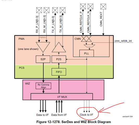
Also, the signals corresponding to <&serdes_wiz0 TI_WIZ_PLL0_REFCLK>, <&serdes_wiz0 TI_WIZ_PLL1_REFCLK>, <&serdes_wiz0 TI_WIZ_REFCLK_DIG>; are not found in TRM. What is it setting ?
Actually, the PCIe configuration had been completed before this change was made. They want to know what this change means.
diff --git a/arch/arm64/boot/dts/ti/k3-am64-main.dtsi b/arch/arm64/boot/dts/ti/k3-am64-main.dtsi
index c29864b3b0e7..4014d80dfae6 100644
--- a/arch/arm64/boot/dts/ti/k3-am64-main.dtsi
+++ b/arch/arm64/boot/dts/ti/k3-am64-main.dtsi
@@ -752,7 +752,7 @@
clocks = <&serdes_wiz0 TI_WIZ_PLL0_REFCLK>, <&serdes_wiz0 TI_WIZ_PHY_EN_REFCLK>;
clock-names = "refclk", "phy_en_refclk";
assigned-clocks = <&serdes_wiz0 TI_WIZ_PLL0_REFCLK>, <&serdes_wiz0 TI_WIZ_PLL1_REFCLK>, <&serdes_wiz0 TI_WIZ_REFCLK_DIG>;
- assigned-clock-parents = <&k3_clks 162 1>, <&k3_clks 162 1>, <&k3_clks 162 1>;
+ assigned-clock-parents = <&serdes_refclk>, <&serdes_refclk>, <&serdes_refclk>;
#address-cells = <1>;
#size-cells = <0>;
#clock-cells = <1>;
Thanks and regards,
Hideaki


