This thread has been locked.

If you have a related question, please click the "Ask a related question" button in the top right corner. The newly created question will be automatically linked to this question.

SK-AM62: SPI on MCU: read only setup on specific Pins

Part Number: SK-AM62
Other Parts Discussed in Thread: SYSCONFIG,

Hi,

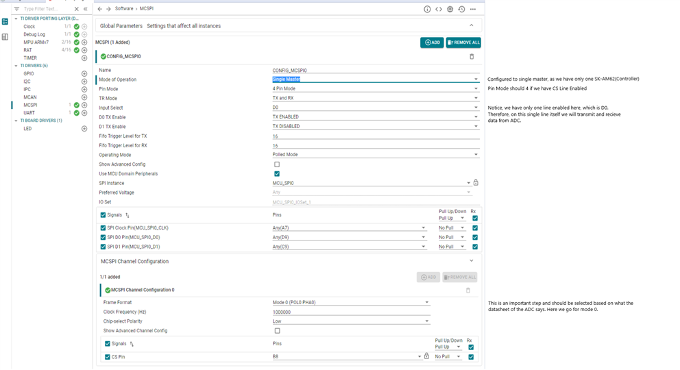
I am currently trying to setup an SPI communication on the AM62 MCU:

SPIO (CLK@A7, MOSI@D9, CS1@B8) with 100kHz

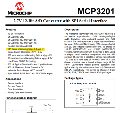
Where the Slave always responds with a 15bit data value on a read from Master.

Can you give some advice on how to setup the Sysconfig, ChConfig (if necessary) and transaction?

I tried to alter the "mcspi_loopback" example but it fails with status 3 (transaction failed)

Best Regards,
Clemens

  • Hello Clemens,

    Thanks for reaching out to Texas Instruments E2E Support Forum.

    I am working on your question. Please expect responses in sometime.

    Regards,

    Vaibhav

    ARM Based Processors | FAQ AM62x & AM62A | FAQ AM64x

  • Hello Clemens,

    Is it possible for you to tell me the slave part number, this way I can provide you the code to receive 15 bit data onto SK-AM62.

    Also, I believe you are using MCU_SPI0, saying this because you simply wrote SPI0 in the question description.

    SPIO (CLK@A7, MOSI@D9, CS1@B8)

    Post your response, I am going to tell you how you can go about setting up SysConfig and SPI Transactions parameters like chDisable, TX and RX Buffer and so on.

    Regards,

    Vaibhav

    ARM Based Processors | FAQ AM62x & AM62A | FAQ AM64x

  • Hi Vaibhav,

    I am trying to get a MCP3201 ADC connected to the MCU_SPI0 as a first example using provided pins.

    MCU_SPI0: CLK@A7, D0@D9 (as input), CS1@B8

    We will then switch to another ADC, when our main board is ready, since the development board we are currently using is missing some PINs. I am confident in switching to different pinouts after getting this test setup running.

    In the final version there will be two TI ADS7822U connected to both MCU_SPI0 and MCU_SPI1 running simultaneous in a timer module with a high reading frequency (200kHz).

    The final solution will use:
    MCU_SPI0: CLK@A7, D0@D9 (as input), CS0@E8

    MCU_SPI1: CLK@D4, D0@A6 (as input), CS1@E5

    I also consider reading 16bit and discard all unused start/stop bits after reading, since this could be an easier solution within the buffer, but this can be decided later.

    Thank you for your help,


    Best Regards,

    Clemens

  • Hello Clemens,

    Thanks for telling about the slave here.

    There are couple of things we need to keep in mind before we initiate SPI between SK-AM62 and the ADC MCP3201.

    Few things are:

    • Clock frequency
    • Frame Format(There are 4 modes, out of which for example if you see in the datasheet below, it says supported MODE 0 and MODE 3)
      • You can read about these 4 modes, just a simple web search would do.
    • Number of lines to be configured

    and so on.

    Please allow me sometime preferably a day or two to get back to you with code and guidance on how we can configure the SysConfig for the same.

    Regards,

    Vaibhav

    ARM Based Processors | FAQ AM62x & AM62A | FAQ AM64x

  • Hi Clemens,

    I have attached below an image of MCPSI SysConfig. On the right hand side you can see the important things you need to know to configure MCSPI with any slave.

    Next up we have code, so lets focus on MCSPI Transaction parameters and how to configure them.

    // Initializing TX Buffer to send dummy bytes to ADC.
    gMcspiTxBuffer[0] = 1;
    gMcspiTxBuffer[1] = 0;
    
    // Initializing RX buffer to 0
    gMcspiRxBuffer[0] = 0;
    gMcspiRxBuffer[1] = 0;
    
    
    /* Initiate transfer */
    MCSPI_Transaction_init(&spiTransaction);
    spiTransaction.channel  = gConfigMcspi0ChCfg[0].chNum;
    spiTransaction.dataSize = 8;
    spiTransaction.csDisable = TRUE;
    spiTransaction.count    = APP_MCSPI_MSGSIZE / (spiTransaction.dataSize/8);
    spiTransaction.txBuf    = (void *)gMcspiTxBuffer;
    spiTransaction.rxBuf    = (void *)gMcspiRxBuffer;
    spiTransaction.args     = NULL;
    
    transferOK = MCSPI_transfer(gMcspiHandle[CONFIG_MCSPI0], &spiTransaction);
    
    if((SystemP_SUCCESS != transferOK) ||
       (MCSPI_TRANSFER_COMPLETED != spiTransaction.status))
    {
        DebugP_assert(FALSE); /* MCSPI transfer failed!! */
    }
    else
    {
        // Printing the 16 bit data read from ADC.
        // HIGH byte is gMcspiRxBuffer[0], LOW byte is gMcspiRxBuffer[1]
        DebugP_log("Data Read is %u \r\n", gMcspiRxBuffer[0] << 8 | gMcspiRxBuffer[1]); // HIGH byte << 8 | LOW byte
    }

    If you look closely its the TX Buffer which has been changed and then at the end we are reading the 16 bit data received from the ADC.

    I am attaching the project here to interface MCSPI(Multi Byte on Single Channel): 
    github.com/.../AM62x - M4F Core MCU Domain

    Thanks,

    Vaibhav

    ARM Based Processors | FAQ AM62x & AM62A | FAQ AM64x

  • Hello Clemens,

    Can you please confirm if you understood the steps I have mentioned in my previous response.

    Regards,

    Vaibhav

    ARM Based Processors | FAQ AM62x & AM62A | FAQ AM64x