Because of the Thanksgiving holiday in the U.S., TI E2E™ design support forum responses may be delayed from November 25 through December 2. Thank you for your patience.

SK-AM62: Improve Poor Bandwidth Utilization on MCSPI Bus

Part Number: SK-AM62
Other Parts Discussed in Thread: AM62P

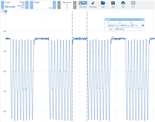
I'm currently working with the MCSPI peripheral on the AM62 SK board using Linux SDK. I have to transfer image-like data and need appropriate bandwidth but when probing the SPI bus I'm seeing that we loose a lot of bandwidth due to regular delays occurring after each sent word (see plot below).

I already reached out to this forum on this topic in an earlier post here. Please read through this post first, the thread is already locked so I need to start a new thread. At this post we enabled DMA which decreased the word delays and with this action we closed the ticket. But now we are using a new peripheral which allows higher transfer rates and now again I struggle satisfying the requirements. Even with DMA the bandwidth is not sufficient and we are forced by the new peripheral to use 25MHz bus clock (not possible to use 50MHz).
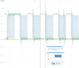
The plot shows the SPI CLK line and we can see that we have a delay of about 200ns after each word sent. It takes about 520ns to transfer one word in total which gets us a bandwidth utilization of around 60%.

Now I wonder if it is possible to decrease those SPI word delays even more?

I also don't know where these delays are introduced (Hardware, Linux kernel, ..), if  someone could tell me more about it this would be nice as well.

Thanks in advance,

Claudio

  • Hi Claudio,

    from your earlier post I understand enabling the DMA allowed you to bring the "inter-byte" gap from ~1.2us down to like 200ns. And you'd like to further trim this 200ns down.

    Doing some quick research it seems like that enabling TURBO mode could bring this down further, see https://git.ti.com/gitweb?p=ti-linux-kernel/ti-linux-kernel.git;a=blob;f=include/linux/platform_data/spi-omap2-mcspi.h;h=3b400b1919a9bd8a9a446da90e37a3582af15de9;hb=refs/heads/ti-linux-6.1.y#l18 but there doesn't seem to be an easy way to turn this on as it's not exposed via DTS.

    For testing purposes, perhaps can you try the below "hack". I've not tested it myself but I hope it would result in the activation of the TURBO mode.

    --- a/drivers/spi/spi-omap2-mcspi.c
    +++ b/drivers/spi/spi-omap2-mcspi.c
    @@ -1134,7 +1134,7 @@ static int omap2_mcspi_transfer_one(struct spi_master *master,
            else if (t->rx_buf == NULL)
                    chconf |= OMAP2_MCSPI_CHCONF_TRM_TX_ONLY;
    
    -       if (cd && cd->turbo_mode && t->tx_buf == NULL) {
    +       if (t->tx_buf == NULL) {
                    /* Turbo mode is for more than one word */
                    if (t->len > ((cs->word_len + 7) >> 3))
                            chconf |= OMAP2_MCSPI_CHCONF_TURBO;

    Regards, Andreas

  • Hi Andreas,

    yes, you got my question right. The TURBO mode sounds promising. I will test out the TURBO mode using your hack to the driver, I will let you know as soo as I've tested it.

    But I just wonder what would be the intended way to enable TURBO mode then? Is there any other API available?

    Regards, Claudio

  • Above I forgot to mention that I explicitly talk about MCSPI2.

    In another post of mine here (this) I talk about a problem enabling DMA on MCSPI0. But on MCSPI2 I was able to enable DMA without problems.

  • But I just wonder what would be the intended way to enable TURBO mode then? Is there any other API available?

    If you dig through the Kernel history you see this is an "old" feature and was used on occasion back then when SoC initialization was done through "board files".... I guess nobody cared enough for this feature to make it available in the "modern-day" device tree world. But this doesn't mean it needs to stay like this or can't be made available if needed. But it all starts with finding out what improvement it brings...

  • Hi Andreas,

    from your earlier post I understand enabling the DMA allowed you to bring the "inter-byte" gap from ~1.2us down to like 200ns. And you'd like to further trim this 200ns down.

    Doing some quick research it seems like that enabling TURBO mode could bring this down further, see https://git.ti.com/gitweb?p=ti-linux-kernel/ti-linux-kernel.git;a=blob;f=include/linux/platform_data/spi-omap2-mcspi.h;h=3b400b1919a9bd8a9a446da90e37a3582af15de9;hb=refs/heads/ti-linux-6.1.y#l18 but there doesn't seem to be an easy way to turn this on as it's not exposed via DTS.

    For testing purposes, perhaps can you try the below "hack". I've not tested it myself but I hope it would result in the activation of the TURBO mode.

    today I could test the hack which should permanently enable SPI TURBO mode. Unfortunately from the experiment I could not see any difference when looking at the probed signals. The inter-byte gaps are still there and of same length independent of our hacked driver.

    Do you think these inter-byte gaps are coming from hardware? Or would you say we should still be able to reduce them further?

    Regards Claudio

  • today I could test the hack which should permanently enable SPI TURBO mode.

    Thanks for trying this out.

    . Unfortunately from the experiment I could not see any difference when looking at the probed signals. The inter-byte gaps are still there and of same length independent of our hacked driver.

    Can you use the standard spidev_test.c tool (part of the Kernel tree) for testing, if you haven't tried this yet? I recall you have experimented with a custom Kernel module but I don't remember if you ever tried this basic tool.

    Do you think these inter-byte gaps are coming from hardware? Or would you say we should still be able to reduce them further?

    I would expect the HW module should be capable of doing better than what you observe, especially with the TURBO mode active. In such a case with the sequence being done mostly in hardware 200ns seems like an awful long time.

    The next step might need to re-create and debug this further on a driver/ hardware level. Perhaps something is missing that prevents the TURBO mode from being fully realized.

    Let me loop in a colleague from the HW team to comment on what the HW module should be capable of.

    Regards, Andreas

  • Let me loop in a colleague from the HW team to comment on what the HW module should be capable of.

    Let me ping the assigned HW engineer for inputs, seems like this got stuck in the process queue.

  • Hello Claudio

    Pls refer below inputs i received from the expert. The expert is continuing to review. I will update the thread when i receive additional inputs.

    If I recall correctly, you should be able to drive the SPI bas a full rate, less one clk cycle to load the serializer, if not with zero delay.

     Force mode should be used (CS constantly asserted) for the best throughput, otherwise it will take time to de-assert/re-assert CS (along with the programmable delays to do so). Not sure if the “brown” trace is CS or not. If it is, the trace suggest FORCE mode is already being used.

     You’ll notice that in this thread (https://e2e.ti.com/support/processors-group/processors/f/processors-forum/1300393/am623-spi-chip-select-taking-longer-time-to-deactivate/4958312#4958312) they have a similar inter-packed gap.

     The DMA should be used to Xfer multiple words for each DMA transfer so that he pipe is not starved while waiting on DMA to complete.

     I’d have to dig more, but I suspect that the s/w config will be the cause of the gap.

    Regards,

    Sreenivasa

  • Hello Sreenivasa,

    thanks for also supporting us here and sorry for the late reply. But now I could find some time to clarify the points you mentioned:

    Force mode should be used (CS constantly asserted) for the best throughput, otherwise it will take time to de-assert/re-assert CS (along with the programmable delays to do so). Not sure if the “brown” trace is CS or not. If it is, the trace suggest FORCE mode is already being used.

    I've made some new measurements which show that force mode is already used. From Linux we are sending one spi_ioc_message containing 4096 bytes. The test code was repeatedly sending those messages, i.e., 4096 bytes are send per CS interval if force mode is enabled. This can be seen from below plots:

    The plots show that one CS cycle takes 2.172ms while one byte takes 520ns seconds to transfer. So we get approx. (2.172ms/520ns =) ~4.1k bytes through per CS. So force mode is enabled.

    But from this thread I understood that the gap there was caused by CS resetting. This will not be the reason for us since we have no CS reset between single bytes.

    The DMA should be used to Xfer multiple words for each DMA transfer so that he pipe is not starved while waiting on DMA to complete.

    The plots above were made while DMA was enabled.


    Regards,

    Claudio

  • Hello Claudio

    Thank you for the inputs.

    Let me review the inputs, check with the expert and comeback.

    Regards,

    Sreenivasa

  • Some information which could be interesting for this thread:

    For some other task I was looking through some patches which have been applied to spi-omap2-mcspi driver in ti-linux repo. There I found this commit: https://git.ti.com/cgit/ti-linux-kernel/ti-linux-kernel/commit/drivers/spi/spi-omap2-mcspi.c?h=ti-linux-6.1.y-cicd&id=2cd757e6292e23b898791d71978c6edf60a251ad. It's titled: "omap2-mcspi: add support for interword delay".

    So it seems like inter-word delays are supported by the driver. Now I wonder how I can set this up as the user. For my tests I have written a small C-program which continuously sends dummy bytes over SPI using spidev API. In this program I setup the spi_ioc_transfer struct and I'm explicitly setting the entry spi_ioc_transfer.word_delay_usecs  to 0. Is this the right API to control the inter-word delays?

    Here's the code of the sample program I mentioned above:

    #include <fcntl.h>
    #include <linux/spi/spidev.h>
    #include <string>
    #include <string.h>
    #include <sys/ioctl.h>
    
    #define BUFF_SIZE 4096
    
    struct spiDev
    {
      int fd;
      int mode = 3;
      uint8_t bits_per_word = 8;
      uint16_t delay_usecs = 0;
      uint8_t word_delay_usecs = 0;
      uint32_t speed_hz = 25000000;
      uint8_t txBuf [BUFF_SIZE] = {0};
      uint8_t rxBuf [BUFF_SIZE] = {0};
    };
    
    int SPIDataRW(spiDev &spidev, int len)
    {
      struct spi_ioc_transfer spiTransfer;
      memset(&spiTransfer, 0, sizeof(spiTransfer));
      spiTransfer.tx_buf = (uint64_t) spidev.txBuf;
      spiTransfer.rx_buf = (uint64_t) spidev.rxBuf;
      spiTransfer.len = len;
      spiTransfer.speed_hz = spidev.speed_hz;
      spiTransfer.bits_per_word = spidev.bits_per_word;
      spiTransfer.word_delay_usecs = spidev.word_delay_usecs;
      spiTransfer.delay_usecs = spidev.delay_usecs;
      // spiTransfer.cs_change = static_cast<bool>(false);
    
      return ioctl(spidev.fd, SPI_IOC_MESSAGE(1), &spiTransfer);
    }
    
    int main(int argc, char **argv)
    {
      char *spi_devname = "/dev/spidev1.0";
    
      if (argc == 2) spi_devname = argv[1];
    
      printf("using %s\n", spi_devname);
    
      spiDev spidev {};
      spidev.fd = open(spi_devname, O_RDWR);
        
      ioctl(spidev.fd, SPI_IOC_WR_MODE32, &spidev.mode);
      ioctl(spidev.fd, SPI_IOC_RD_MODE32, &spidev.mode);
      ioctl(spidev.fd, SPI_IOC_WR_BITS_PER_WORD, &spidev.bits_per_word);
      ioctl(spidev.fd, SPI_IOC_RD_BITS_PER_WORD, &spidev.bits_per_word);
      ioctl(spidev.fd, SPI_IOC_WR_MAX_SPEED_HZ, &spidev.speed_hz);
      ioctl(spidev.fd, SPI_IOC_RD_MAX_SPEED_HZ, &spidev.speed_hz);
        
      printf("start sending one byte per tx (BUFF_SIZE = %i)\n", BUFF_SIZE);
      while(true)
      {
        spidev.txBuf[0] = 0xAA; // write dummy byte
        SPIDataRW(spidev, BUFF_SIZE);
      }
    
      return 0;
    }

  • Hi Claudio,

    For my tests I have written a small C-program which continuously sends dummy bytes over SPI using spidev API. In this program I setup the spi_ioc_transfer struct and I'm explicitly setting the entry spi_ioc_transfer.word_delay_usecs  to 0. Is this the right API to control the inter-word delays?

    You can try setting it to something non-zero (something large) to see if it has any impact, this would confirm you are using the API correctly.

    This being said I doubt the default behavior would be to introduce a delay, and the user is required to set it to zero to make it go away. But rather the API can be used to introduce _additional_ delays. Otherwise this would be a really poor design IMHO.

    I'll have some time set aside to experiment with this next week to re-create this and see if we can make any improvements.

    Regeards, Andreas

  • Hi Andreas,

    I just did the following tests:

    • I was setting the spi_ioc_transfer.delay_usecs parameter to 0, and 1000. According to the description I was expecting a delay introduced between each SPI transfer (i.e., after each 4096 bytes sent in the example above). After probing the SPI clock signal I can confirm that this behavior.
    • Then I was setting the spi_ioc_transfer.word_delay_usecs parameter to 0, 100, and 255 (its a u8). This parameter however does definitely not impact the gaps between each byte: the inter-byte gaps stayed the same for all 3 values. After probing the clock I could Interestingly see that instead the inter-transfer gaps (the gaps which can also be manipulated with the delay_usecs parameter, see above) were increasing. At word_delay_usecs == 0 the inter-transfer gaps were ~50us, at 100 the gap increased to ~160us, and at 255 the gap became ~330us. From documentation of this parameter I was not expecting this, maybe there is a bug somewhere?
  • Hi Claudio,

    I was setting the spi_ioc_transfer.delay_usecs parameter to 0, and 1000. According to the description I was expecting a delay introduced between each SPI transfer (i.e., after each 4096 bytes sent in the example above). After probing the SPI clock signal I can confirm that this behavior.

    Good to know.

    Then I was setting the spi_ioc_transfer.word_delay_usecs parameter to 0, 100, and 255 (its a u8). This parameter however does definitely not impact the gaps between each byte: the inter-byte gaps stayed the same for all 3 values. After probing the clock I could Interestingly see that instead the inter-transfer gaps (the gaps which can also be manipulated with the delay_usecs parameter, see above) were increasing. At word_delay_usecs == 0 the inter-transfer gaps were ~50us, at 100 the gap increased to ~160us, and at 255 the gap became ~330us. From documentation of this parameter I was not expecting this, maybe there is a bug somewhere?

    Could be that not all drivers implement/support this feature, this doesn't necessarily need to be a bug. Will keep an eye out for this as I look at/work with the SPI driver.

    I was finally able to setup an AM62-based SPI test setup with logic analyzer connected and everything and started analyzing and experimenting with the "gap" behavior in more detail.

    Regards, Andreas

  • Hi Claudio,

    I saw your follow-on post about this thread becoming locked. This happens automatically after 1mo of inactivity but I just unlocked it so we can continue the discussion here. Will delete your additional post about this to keep things more organized. As for the status, I got side-tracked with other activities, but my plate has cleared some and I'm planning on picking this back up here first thing next week.

    Regards, Andreas

  • Hi Andreas,

    thanks for reopening this thread, this will make the communication easier. I was already thinking that it was automatically closed. 

    That's good to hear that you now have time, maybe you have more success than I have. From my side there was no success so far. Let me hear when you found something!

    Regards, Claudio

  • Hi Claudio,

    Thank you.

    We will update the thread as we make some progress.

    Regards,

    Sreenivasa

  • Hi Claudio,

    I did some more investigation and found there's also a limit of 160 bytes that determines whether the DMA is actually used for the transfers, despite being configured correctly using the device tree. Can you please review my write up at https://e2e.ti.com/support/processors-group/processors/f/processors-forum/1356551/faq-am625-optimizing-spi-transfer-inter-byte-gaps-using-the-dma-in-linux to see if this helps. But again this is assuming you do smaller than 160 bytes of transfers, but it looks like you already do larger transfers (4K). Still it will be good to confirm that DMA transfers are in fact used with the debug aids given at the end of the E2E FAQ.

    The next step might need to re-create and debug this further on a driver/ hardware level. Perhaps something is missing that prevents the TURBO mode from being fully realized.

    Just to close the loop here, I found the TURBO mode only applies to short, RX-only transfers. I don't think this applies to your scenario.

    Regards, Andreas

  • Hi Claudio,

    another thing you can try is to use FIFO mode for SPI transfers (instead of DMA), which should also help to reduce inter-byte gaps. We briefly had a patch to enable that on our ti-linux-6.1.y tree but it was reverted due to some system-test regression it caused. Still, it could be valuable for you to apply this patch and try to see what it does to your inter-byte gaps.

    Can you please cherry-pick this commit here on top of your ti-linux-6.1.y tree and give this a try (and make sure to remove DMA properties from your device tree node so that PIO mode is used!):

    https://git.ti.com/cgit/ti-linux-kernel/ti-linux-kernel/commit/?id=a78c61d33ac41454b4149edbe1552184b0ba0fd2

    spi: omap2-mcspi: Add FIFO support without DMA
    commit 75223bbea840e125359fc63942b5f93462b474c6 upstream.
    
    Currently, the built-in 64-byte FIFO on the MCSPI controller is not
    enabled in PIO mode and is used only when DMA is enabled. Enable the
    FIFO in PIO mode by default and fallback only if FIFO is not available.
    When DMA is not enabled, it is efficient to enable the RX FIFO almost
    full and TX FIFO almost empty events after each FIFO fill instead of
    each word. Update omap2_mcspi_set_fifo() to enable the events accordingly
    and also rely on OMAP2_MCSPI_CHSTAT_RXS for the last transfer instead of
    the FIFO events to handle the case when the transfer size is not a
    multiple of FIFO depth.
    
    See J721E Technical Reference Manual (SPRUI1C), section 12.1.5
    for further details: http://www.ti.com/lit/pdf/spruil1
    
    Link: https://lore.kernel.org/r/20231013092629.19005-1-vaishnav.a@ti.com
    Signed-off-by: Mark Brown <broonie@kernel.org>
    Signed-off-by: Vaishnav Achath <vaishnav.a@ti.com>

    Of course not using the DMA will probably create other challenges, namely making sure Linux and system activity doesn't prevent one from keeping the FIFO buffer full. Working with another customer I was able to address this related concern through a real-time tuning of the system, see steps 1 through 4 outlined here: https://e2e.ti.com/support/processors-group/processors/f/processors-forum/1340973/sk-am62-spi-signal-discontinuity-problem/5157777#5157777   This seems to only help in a multi-core system though. So basically the solution was to apply above FIFO patch, PLUS the steps 1 through 4 in the post I linked to.

    Regards, Andreas

  • At this post we enabled DMA which decreased the word delays and with this action we closed the ticket. But now we are using a new peripheral which allows higher transfer rates and now again I struggle satisfying the requirements. Even with DMA the bandwidth is not sufficient and we are forced by the new peripheral to use 25MHz bus clock (not possible to use 50MHz).

    Regarding the use of DMA, there is one more thing you can try. This might be a long shot in the context of SPI and I haven't tried it myself yet but there is still the option to implement cache coherent I/O transactions via the ACP port using initiators like DMA with ASEL set to 14 or 15. This is utilized by Linux Ethernet for higher performance. Basically, use '15' as the final parameter in the 'dmas' device tree definitions (instead of '0'), like this:

    diff --git a/arch/arm64/boot/dts/ti/k3-am625-sk-mcspi-loopback.dtso b/arch/arm64/boot/dts/ti/k3-am625-sk-mcspi-loopback.dtso
    index fbdc1d055131..bff4b8487692 100644
    --- a/arch/arm64/boot/dts/ti/k3-am625-sk-mcspi-loopback.dtso
    +++ b/arch/arm64/boot/dts/ti/k3-am625-sk-mcspi-loopback.dtso
    @@ -41,6 +41,8 @@
            #size-cells = <0>;
            pinctrl-0 = <&main_spi0_pins_default>;
            pinctrl-names = "default";
    +       dmas = <&main_pktdma 0xc300 15>, <&main_pktdma 0x4300 15>;
    +       dma-names = "tx0", "rx0";
            spidev@0 {
                    /*
                     * Using spidev compatible is warned loudly,

    Regards, Andreas

  • Hi Andreas,

    I am writing on behalf of Claudio, as he is on holiday until 10th of June.

    Yes, we are using 4k packages and do not really care about the performance of shorter packages. So use case wise we can ignore the packages smaller than 160Byte. For the longer packages we are sure that DMA is used (we can see this clearly from the timings in the system and the CPU load). We could in principle think about testing this mentioned FIFO approach to see if the system can get rid of these byte gaps in principle. However, using an RT patched Linux Kernel is something we would really like to avoid. Also skipping the DMA would not really be a nice solution for us. 

    Therefore your below suggestion regarding improved DMA usage would be more promising to us. Claudio will try it out, once he is back.

    Regards,

    Christian

  • Hi Christian,

    thanks for the background, and understand & agree with your assessment. I think we are doing everything we can to keep the "SPI module fed" by employing DMA as much as possible. The additional suggestion I made may or may not improve things further but I'm not sure, but at least we need to try it. Beyond that, I can't think of anything that can be tried in software to further speed up things. Except perhaps using a PRU core to implement a custom SPI solution...

    Will be on the lookout for your feedback.

    Regards, Andreas

  • Hi Andreas,

    I'm already back from holiday, the 10th of June mentioned above was a misunderstanding.

    I've gone through your proposed solutions above one after another. In general I aggree with Christians answer, but here are some additional notes from my side:

    I did some more investigation and found there's also a limit of 160 bytes that determines whether the DMA is actually used for the transfers, despite being configured correctly using the device tree. Can you please review my write up at https://e2e.ti.com/support/processors-group/processors/f/processors-forum/1356551/faq-am625-optimizing-spi-transfer-inter-byte-gaps-using-the-dma-in-linux to see if this helps. But again this is assuming you do smaller than 160 bytes of transfers, but it looks like you already do larger transfers (4K).

    We do read even more than 4k Bytes per SPI transfer (we tweaked the spidev.bufsiz parameter) and we are pretty sure that DMA is used. Earlier we ran into severe CPU load problems since spidev does not provide async io. That's why we went for DMA which will have a similar effect. We can see that DMA is enabled directly from monitoring CPU load (and even by looking at the framerate of image data transferred via SPI). 

    another thing you can try is to use FIFO mode for SPI transfers (instead of DMA), which should also help to reduce inter-byte gaps. We briefly had a patch to enable that on our ti-linux-6.1.y tree but it was reverted due to some system-test regression it caused. Still, it could be valuable for you to apply this patch and try to see what it does to your inter-byte gaps.

    As Christian A. already mentioned we have to use DMA in the final solution. But still I will check on the FIFO mode because I'm curious if we can get rid of the byte gaps this way. I've not yet tested it, I will post the results here as soon as I'm done.

    Regarding the use of DMA, there is one more thing you can try. This might be a long shot in the context of SPI and I haven't tried it myself yet but there is still the option to implement cache coherent I/O transactions via the ACP port using initiators like DMA with ASEL set to 14 or 15. This is utilized by Linux Ethernet for higher performance. Basically, use '15' as the final parameter in the 'dmas' device tree definitions (instead of '0'), like this:

    I had big hopes in this solution so I tested it right away. Unfortunately I observe the same behavior as with DMA but without Cache Coherent IO. The byte gaps are of same size:

    Note: After the tests above I was flashing the latest TI SDK image v9.02.01.10 (before we were using v9.01.00.08) and tested the SPI transfers again. However the latest image yields the same results.

    Regards, Claudio

  • Hi Claudio,

    I had big hopes in this solution so I tested it right away. Unfortunately I observe the same behavior as with DMA but without Cache Coherent IO. The byte gaps are of same size:

    Ok thanks for the test. It was a long shot but something that needed to be tried. Now that we made sure the DMA is used to feed the module, which is all done in hardware, it looks like the best we can do is 200ns in that setup with your given SPI clock frequency. I don't think there's anything else you can do in SW to push this further. However I do think gap-less SPI operation is desirable and should be possible with any SPI host really, so I wonder what the HW limitation is preventing this, and if there is a way to improve this for future versions of our hardware. This is an internal discussion to be had, nothing that would help you here on your current project/device.

    But still I will check on the FIFO mode because I'm curious if we can get rid of the byte gaps this way. I've not yet tested it, I will post the results here as soon as I'm done.

    Yes, please test this too. For sure it'll increase CPU usage and may make the transfer more susceptible to "timing disturbances" but the point is to see if there is any way to push below those 200ns at least momentarily, which in average could result in higher throughput.

    One way (not ideal, but possible) to achieve true seamless and gap-free SPI transfers today would be to use the PRU accelerator to implement a "soft SPI". We don't have this ready as a solution, but there is a  "soft UART" solution available comprising the Linux driver and corresponding PRU code that one could adopt for SPI usage.

    Thanks, Andreas

  • Hi Andreas,

    today I finally could test the PIO FIFO patch for MCSPI.

    First of all from the commit message of this patch (here) I could read that FIFO mode should me already enabled when we are using DMA. Since we are using DMA and we still have byte gaps I was not expecting to get entirely rid of the gaps with this patch. However we could already see earlier that as soon as we enable DMA the byte gaps are getting quite a bit smaller.

    And indeed, when I disable DMA but add the PIO FIFO patches to MCSPI driver, I can observe the same behavior:


    (Left: MCSPI0 CLK PIO, no DMA, no FIFO patch; Right: MCSPI0 CLK PIO, no DMA, FIFO patch applied)

    You can see that after adding the patch the byte gaps are of same length as when DMA would be enabled. So the FIFO definitely has an impact on the byte gaps. however we still cannot get rid of them completely.

    One way (not ideal, but possible) to achieve true seamless and gap-free SPI transfers today would be to use the PRU accelerator to implement a "soft SPI". We don't have this ready as a solution, but there is a  "soft UART" solution available comprising the Linux driver and corresponding PRU code that one could adopt for SPI usage.

    At the moment we cannot really spent the time implementing a soft SPI controller, so we would like to avoid it. But I will keep it in mind as backup plan.

    Now that we made sure the DMA is used to feed the module, which is all done in hardware, it looks like the best we can do is 200ns in that setup with your given SPI clock frequency. I don't think there's anything else you can do in SW to push this further. However I do think gap-less SPI operation is desirable and should be possible with any SPI host really, so I wonder what the HW limitation is preventing this, and if there is a way to improve this for future versions of our hardware. This is an internal discussion to be had, nothing that would help you here on your current project/device

    Yes I can understand this. It would be nice if we could understand this problem and its root cause better and maybe in some future releases (hardware or kernel) we can then get rid of the gaps finally. On our side here we now started discussion with our sensor supplier and we try to find a solution using a higher clock frequency.

    Thanks for your support and all your proposals, at least we now understand the system a bit better.

    Regards, Claudio

  • Hi Claudio,

    thanks for the help continuing investigating this, and always providing detailed feedback. Actually if you don't mind there is one more experiment I'd like you to try. It is based on some of my past experience (on MCUs) where I have seen module-specific delays being a function of the input clock to those modules. In this spirit I think we can try increasing the functional clock frequency from the default 50MHz to something else, like 100MHz. You can do this by adding the pair of assigned-clocks and assigned-clock-rates properties to the main_spi0 device tree node, as shown in the below patch:

    a0797059@dasso:~/git/linux (ti-linux-6.1.y-spi-speed-test-dev)
    $ git show
    commit a9b90a450107b4e368b9f14709f10da2be1c2bde (HEAD -> ti-linux-6.1.y-spi-speed-test-dev)
    Author: Andreas Dannenberg <dannenberg@ti.com>
    Date:   Wed Jun 5 00:29:30 2024 -0500
    
        arm64: dts: ti: k3-am625-sk: Use DMA and increase fclk frequency
    
        This is a test to check the impact of those changes on the inter-byte
        gap of SPI transfers.
    
        Signed-off-by: Andreas Dannenberg <dannenberg@ti.com>
    
    diff --git a/arch/arm64/boot/dts/ti/k3-am625-sk-mcspi-loopback.dtso b/arch/arm64/boot/dts/ti/k3-am625-sk-mcspi-loopback.dtso
    index fbdc1d055131..53506f3006ea 100644
    --- a/arch/arm64/boot/dts/ti/k3-am625-sk-mcspi-loopback.dtso
    +++ b/arch/arm64/boot/dts/ti/k3-am625-sk-mcspi-loopback.dtso
    @@ -41,6 +41,15 @@
            #size-cells = <0>;
            pinctrl-0 = <&main_spi0_pins_default>;
            pinctrl-names = "default";
    +
    +       /* Enable use of DMA */
    +       dmas = <&main_pktdma 0xc300 0>, <&main_pktdma 0x4300 0>;
    +       dma-names = "tx0", "rx0";
    +
    +       /* Bump functional clock to 100MHz (from 50MHz) */
    +       assigned-clocks = <&k3_clks 141 0>;
    +       assigned-clock-rates = <100000000>;
    +
            spidev@0 {
                    /*
                     * Using spidev compatible is warned loudly,

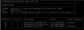
    Once you do this you should be able to verify the new functional clock frequency as follows with the k3conf command (example is from AM62P, but same should apply to AM62 non-P),

    root@am62pxx-evm:/proc/device-tree/bus@f0000/spi@20100000# k3conf dump clock 141
    |------------------------------------------------------------------------------|
    | VERSION INFO                                                                 |
    |------------------------------------------------------------------------------|
    | K3CONF | (version 0.3-nogit built Fri Oct 06 12:20:16 UTC 2023)              |
    | SoC    | AM62Px SR1.0                                                        |
    | SYSFW  | ABI: 3.1 (firmware version 0x0009 '9.1.8--v09.01.08 (Kool Koala))') |
    |------------------------------------------------------------------------------|
    
    |-----------------------------------------------------------------------------------------------------------------------|
    | Device ID | Clock ID | Clock Name                                                 | Status          | Clock Frequency |
    |-----------------------------------------------------------------------------------------------------------------------|
    |   141     |     0    | DEV_MCSPI0_CLKSPIREF_CLK                                   | CLK_STATE_READY | 100000000       | <== THIS!!
    |   141     |     1    | DEV_MCSPI0_IO_CLKSPII_CLK                                  | CLK_STATE_READY | 0               |
    |   141     |     2    | DEV_MCSPI0_IO_CLKSPII_CLK_PARENT_BOARD_0_SPI0_CLK_OUT      | CLK_STATE_READY | 0               |
    |   141     |     3    | DEV_MCSPI0_IO_CLKSPII_CLK_PARENT_SPI_MAIN_0_IO_CLKSPIO_CLK | CLK_STATE_READY | 0               |
    |   141     |     4    | DEV_MCSPI0_IO_CLKSPIO_CLK                                  | CLK_STATE_READY | 0               |
    |   141     |     5    | DEV_MCSPI0_VBUSP_CLK                                       | CLK_STATE_READY | 125000000       |
    |-----------------------------------------------------------------------------------------------------------------------|

    I'm curious what this will do...

    1. To the inter-byte gaps. Do they get smaller?
    2. To the effective SPI clock frequency. I think it should stay the same (not double) due to how the Kernel clock framework works.

    So since you have the setup if you could give this a quick try that would be great. Note that in the very remote case it does help; we'd still need to validate internally if this is even a valid thing to do (not violating any internal timing specs, for example). So please don't get too excited about this experiment.

    Regards, Andreas

  • Hi Andreas,

    it's an interesting idea and I gave it a try. But it seems that 100MHz are not supported for this clock. After patching the dtbo as shown by you I tried the k3conf command and it still shows 50MHz Clock Frequency:

    I could confirm that dtbo was applied. Also the DMA was enabled. By looking at the MCSPI0_CLK signal I could also see no changes (still ~200ns byte gap).

    I was earlier doing already an experiment where I was investigating the behavior of the byte gaps over different MCSPI0_CLK. I will share the results with you as attachment to this comment, maybe it helps you. I just remember that the byte gaps become bigger by increasing the SPI CLK. For me this result felt a bit strange because I was thinking that those gaps were caused by internal processing which cannot keep up especially when using high SPI CLK frequencies (e.g., some buffers which need to be filled, etc.). However those results were pointing in another direction but I was not further looking into it.

    Regards, Claudio


    ByteGapExperiments.xlsx

  • Hi Claudio,

    it's an interesting idea and I gave it a try. But it seems that 100MHz are not supported for this clock. After patching the dtbo as shown by you I tried the k3conf command and it still shows 50MHz Clock Frequency:

    Can you try the equivalent of the DTS changes but from the command line? (Again, I'm using AM62P here, so that could be why it's not working on AM62 that you have, but I'll double-check tomorrow on my AM62 board as well).

    root@am62pxx-evm:~# k3conf set clock 141 0 100000000
    |------------------------------------------------------------------------------|
    | VERSION INFO                                                                 |
    |------------------------------------------------------------------------------|
    | K3CONF | (version 0.3-nogit built Fri Oct 06 12:20:16 UTC 2023)              |
    | SoC    | AM62Px SR1.0                                                        |
    | SYSFW  | ABI: 3.1 (firmware version 0x0009 '9.1.8--v09.01.08 (Kool Koala))') |
    |------------------------------------------------------------------------------|
    
    |-----------------------------------------------------------------------------------------------------------------------|
    | Device ID | Clock ID | Clock Name                                                 | Status          | Clock Frequency |
    |-----------------------------------------------------------------------------------------------------------------------|
    |   141     |     0    | DEV_MCSPI0_CLKSPIREF_CLK                                   | CLK_STATE_READY | 100000000       |
    |   141     |     1    | DEV_MCSPI0_IO_CLKSPII_CLK                                  | CLK_STATE_READY | 0               |
    |   141     |     2    | DEV_MCSPI0_IO_CLKSPII_CLK_PARENT_BOARD_0_SPI0_CLK_OUT      | CLK_STATE_READY | 0               |
    |   141     |     3    | DEV_MCSPI0_IO_CLKSPII_CLK_PARENT_SPI_MAIN_0_IO_CLKSPIO_CLK | CLK_STATE_READY | 0               |
    |   141     |     4    | DEV_MCSPI0_IO_CLKSPIO_CLK                                  | CLK_STATE_READY | 0               |
    |   141     |     5    | DEV_MCSPI0_VBUSP_CLK                                       | CLK_STATE_READY | 125000000       |
    |-----------------------------------------------------------------------------------------------------------------------|
    

    Regards, Andreas

  • Hi Andreas,

    I tested to set the clock from command line but the command was giving an error:

    Actually when I try with 50MHz the command worked:

    I guess 100MHz are simply not supported by this bus.

    Regards, Claudio 

  • Ah ok, thanks for trying this. Looks like a difference between AM62 an AM62P (which I used) in terms of clock tree/architecture.

    Anyways I think we have pretty much exhausted what we can try from a SW POV, and the smallest inter-byte gap we have achieved was 200ns @ 25MHz SPI clock. Let me pick up the discussion with one of our HW/system architects on this. Will report back here in a couple of days.

    Thanks, Andreas

  • Hi Claudio,

    going back to this previous topic of "TURBO Mode"....

    today I could test the hack which should permanently enable SPI TURBO mode. Unfortunately from the experiment I could not see any difference when looking at the probed signals. The inter-byte gaps are still there and of same length independent of our hacked driver.

    Do you think these inter-byte gaps are coming from hardware? Or would you say we should still be able to reduce them further?

    I've since been able to experiment with this further and was able to get it to work (I think) and I've seen dramatic improvements in inter-byte gap times. Can you please go back to this page here https://e2e.ti.com/support/processors-group/processors/f/processors-forum/1356551/faq-am6x-optimizing-spi-transfer-inter-byte-gaps-using-the-dma-in-linux and review the new section I added at the end "TURBO Mode (Experimental)". Since you are a "McSPI Peripheral Power User" and are very much vested in good/fast operation of this module I would very much appreciate if you could look at this/test this one more time from your side. It all seems to work on the bench, but by no means I've done any representative real-world testing.

    Thanks, Andreas

  • Hi Andreas,

    First of all thanks for the efforts! Those results sound promising and I directly wanted to test it on our side.

    I integrated the "McSPI Turbo Mode" patches attached to your article to our custom kernel. I then tested it by doing some dummy SPI transfers using a simple program which uses Spidev to dump out junks of 4K bytes over SPI. I probed the signals and indeed I can see the byte gaps are now decreased to about 74ns:

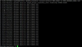
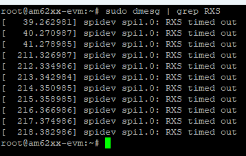
    Since I'm using SPI to receive image data from a camera-like sensor, I next tested a simple demo which reads the sensor data from SPI. When I run this I'm however not receiving any data, instead I'm getting the error RXS timed out regularly printed into dmesg:

    When I then quit the demo and afterwards try executing the same SPI test program which I used in the beginning (and which was working) it will also not work anymore. So it seems that the sensor demo causes a crash inside the kernel. The strange thing is that the sensor demo is not doing so much different to read out the data from the sensor compared to the simple Spidev demo. Both are using the following spi_ioc_transfer buffer configuration:

    where tx_buf and rx_buf are both 4096 bytes and there is only the first byte set with data in tx_buf (which I'm also doing in the simple demo). However if the TX buffer would be empty the sensor demo would not receive any data from sensor since TX contains the command to request an image. Is there anything I missed? Else I unfortunately don't think this is a solution for our problem.

    I also observed that our patched (and Turbo Mode capable) kernel shows these errors on each boot:

    I remember that the Turbo Mode feature was once reverted on TI's kernel. What was the actual reason for reverting it? And, is the feature reintegrated in the meanwhile or should we better not use it in production?

    Regards, Claudio

  • Hi Claudio,

    I integrated the "McSPI Turbo Mode" patches attached to your article to our custom kernel. I then tested it by doing some dummy SPI transfers using a simple program which uses Spidev to dump out junks of 4K bytes over SPI. I probed the signals and indeed I can see the byte gaps are now decreased to about 74ns:

    Thanks for giving this a spin. It looked "good" on my quick bench testing and it looks like you were able to re-create this at least to some degree as well, but of course what I put together was just an initial proof of concept to see how well it would actually work in a more real-world scenario.

    Since I'm using SPI to receive image data from a camera-like sensor, I next tested a simple demo which reads the sensor data from SPI. When I run this I'm however not receiving any data, instead I'm getting the error RXS timed out regularly printed into dmesg:

    What's different about that code from a source and flow POV? Can you pin things breaking done to one specific aspect?

    When I then quit the demo and afterwards try executing the same SPI test program which I used in the beginning (and which was working) it will also not work anymore. So it seems that the sensor demo causes a crash inside the kernel.

    That's not good Slight smile Even let's say if things are mis-configured from a user space POV or there's some software bug the peripheral module / driver should not end up in a state it can't be recovered from.

    The strange thing is that the sensor demo is not doing so much different to read out the data from the sensor compared to the simple Spidev demo. Both are using the following spi_ioc_transfer buffer configuration:

    Ah ok so you did look at it more closely, that answers my earlier question.

    where tx_buf and rx_buf are both 4096 bytes and there is only the first byte set with data in tx_buf (which I'm also doing in the simple demo). However if the TX buffer would be empty the sensor demo would not receive any data from sensor since TX contains the command to request an image. Is there anything I missed? Else I unfortunately don't think this is a solution for our problem.

    Can you provide an updated spidev_test.c source file that  exhibits the the issue?

    I remember that the Turbo Mode feature was once reverted on TI's kernel. What was the actual reason for reverting it? And, is the feature reintegrated in the meanwhile or should we better not use it in production?

    Several of the features have undergone work over the years, and were removed and re-added in cases. Unfortunately there's no history really what happened other than what may be captured in the commit messages, a lot of the people that worked on those things are no longer around. As far as I know no work is currently happening on the driver but since reducing the inter-byte gap is a pretty common request I'd like to open a case for the development team to pick this up and provide an official solution. But for such an effort it's good to provide some starting point (as well as justification a.k.a. "business case") to the team, which is what our discussion here is about, which will help to get this officially kicked off.

    Regards, Andreas

  • Hi Andreas,

    regarding the business case: We have one product where one of the major KPIs is depending on the read speed of this API. Without the fix we will not be able to fully fulfill that requirement. I will contact our key account manager at TI, so he can get in contact with you and probably support you with the needed details.

    Best regards,

    Christian

  • Hi Andreas,

    I was reading through your article (here) more in detail now. You mention there that Turbo Mode only works in Rx only mode:

    is limited to RX-only transfers

    What exactly does this mean? In our case, as I already said earlier, we are communicating to a sensor and we need to use full-duplex mode. The communication flow is generally like this: we put an instruction byte into Tx which instructs the sensor to send data. But in the same SPI message we also expect to get the answer from the sensor into Rx. Can it be that the Tx buffer will never be filled in Turbo Mode? This could at least explain why we do not get any data from the sensor when using Turbo Mode.

    Regards, Claudio

  • Hi Christian,

    t. I will contact our key account manager at TI, so he can get in contact with you and probably support you with the needed details.

    I saw this, let's continue the discussion offline.

    Regards, Andreas

  • Hi Claudio,

    ou mention there that Turbo Mode only works in Rx only mode:

    This was based on my earlier interpretation of the Linux driver only supporting RX mode; in combination with what I think a bit unclear discussion of this feature in the User's Guide that to me also _sounded_ like it might be an RX-only feature, concluding that this is just what the HW was designed to do. However some time after that I was discussing about this with a member of our silicon/IP test team and he said it should work in both RX+TX mode and he created a proof of concept test code that showed this feature working. As a follow-on to this I enabled TURBO mode also for TX in the Linux driver and did some limited bench testing in loopback mode to confirm that RX+TX seemed to work, which is when I asked for your help to also test this in a more real-world scenario, which is when you encountered some issues. This is basically the story here.

    I still believe this feature should be something we can (and should) make work and officially available if possible. However since this is not something that can be "quickly done on the side" as part of E2E forum support I suggested we need to build a case to get the R&D team involved to properly develop, validate, and deploy (via SDK and upstream) this feature.

    Regards, Andreas