- Ask a related questionWhat is a related question?A related question is a question created from another question. When the related question is created, it will be automatically linked to the original question.
This thread has been locked.
If you have a related question, please click the "Ask a related question" button in the top right corner. The newly created question will be automatically linked to this question.
Hello,
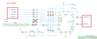
We have a board using 66AK2G processor and a SPI/I2C to UART chip, MAX3107, see below. We are using SPI1 bus to control max3107.
We do not use DCAN0 and DCAN1, so K2G's H21,H22 pins are used as simple GPIO input/output pins.

There are several required properties of the max3107 in device tree,
required:
  - compatible
  - reg
  - interrupts
  - clocks
  - clock-names
I am wondering how to add the interrupts information to the device tree? Also, is the clock information, clk_4M , correct? Entries that are no sure enough are in red color text.
/dts-v1/;
#include "keystone-k2g.dtsi"
/ {
compatible = "ti,k2g-evm", "ti,k2g", "ti,keystone";
model = "Texas Instruments K2G General Purpose EVM";
memory@800000000 {
device_type = "memory";
reg = <0x00000008 0x00000000 0x00000000 0x80000000>;
};
. . . . .
clk_4M: clk_4M { /* for spi uart max3107 */
compatible = "fixed-clock";
#clock-cells = <0>;
clock-frequency = <4000000>;
};
};
&spi1 {
pinctrl-names = "default";
pinctrl-0 = <&spi1_pins>;
status = "okay";
/* UART expander, MAX3107 */
max310x_0: max0@0 {
compatible = "maxim,max3107";
spi-max-frequency = <10000000>; //<125000000>
reg = <0>;
interrupt-parent = <?>; /* optional */
interrupts = <? ?>; /* required */
clocks = <&clk_4M>;
clock-names = "osc";
};
};
Tom
Hello Tom,
Thank you for the query.
Let me check if we have an expert familiar with max3107 and the processor who could support.
Please expect delay in response.
Regards,
Sreenivasa
Hello Tom,
We can support questions on the forum about TI hardware, or TI software. But we cannot answer questions about hardware or software that was developed by other companies.
If you find any issues with our SPI peripheral or the TI SPI driver, please reach out to us and we can offer assistance! But you will need to reach out to Analog devices for questions about how to use their part with a Linux processor.
Regards,
Nick
Nick,
I am actually asking how to use TI K2G chip, how TI chip assign interrupts for external devices, nothing to do with MAX3107. The external chip can be either a SPI device or DDR or whatever that has interrupt service requirement.
Tom
For example, if the correct answer is something like below, can you tell me where to find index of the interrupt within this TI K2G Processor? there must be a bunch of interrupts, which is more appropriate? ....
			interrupt-parent = <&gpio>;
			interrupts = <160 1>;
Hi Tom,
let me take a stab at this. Just as a disclaimer, I never worked on this legacy platform, and also don't have access to it, so my comments here are based on looking at the documentation and kernel sources (untested).
&spi1 {
pinctrl-names = "default";
pinctrl-0 = <&spi1_pins>;
status = "okay";
/* UART expander, MAX3107 */
max310x_0: max0@0 {
compatible = "maxim,max3107";
spi-max-frequency = <10000000>; //<125000000>
reg = <0>;
interrupt-parent = <?>; /* optional */
interrupts = <? ?>; /* required */
clocks = <&clk_4M>;
clock-names = "osc";
};
};
You'll need something like the below...
interrupts = <GIC_SPI 164 IRQ_TYPE_EDGE_RISING>;
This particular example was taken from the uart0 definition in arch/arm/boot/dts/keystone-k2g.dtsi. The GIC_SPI (Shared Peripheral Interrupt) index for each peripheral can be found in the SPI Event No column of Table 6-2. AINTC Interrupt Sources in the 66AK2Gx Multicore DSP + ARM Keystone II System-on-Chip (SOC) TRM. When you check that TRM table you can find 164 listed there for UART_0, which corresponds with the above. Just consider this as an starting point, of course we are after GPIO interrupts here.
Looking at the TRM further it looks like one way to get interrupts from GPIO is by using one of the GPIOMUX[0...31] inputs as an interrupt source, corresponding to GIC_SPI event numbers 448...479. Furthermore, whatever GPIOMUX[0...31] input was chosen needs to be configured through the associated BOOTCFG_EVENT_MUXCTLx register, see section 5.1.3.1.7 Event Mux Control Registers in the TRM. There are some E2E posts around this like here: https://e2e.ti.com/support/processors-group/processors/f/processors-forum/943300/ccs-66ak2g12-interrupt-not-working-in-arm-for-mux-event-selection-value-other-than-1 and it looks like this will need to be done in a bare-metal environment (bootloader). An alternative to this could be to use the GPIO bank interrupt instead, which translates to GIC_SPI event numbers 432...446, in which case you should getaway without having to configure the Event Mux Control Registers. If you see those interrupts are already assigned with the GPIO modules in arch/arm/boot/dts/keystone-k2g.dtsi.
clk_4M: clk_4M { /* for spi uart max3107 */
compatible = "fixed-clock";
#clock-cells = <0>;
clock-frequency = <4000000>;
};
This looks correct.
Regards, Andreas
Dear Andreas,
Thanks for the detailed explanation. I use an easy way to get interrupts from GPIO.
See how gpio1_12 pin is used in evm k2g:
https://elixir.bootlin.com/linux/v4.19.94/source/arch/arm/boot/dts/keystone-k2g-evm.dts
Since in our schematics, the irq pin of MAX3107 is connected to K2G Processor's GPIO1_67 pin. We just need to add MAX3107 to the dts as following:
&gpio1 {
status = "okay";
};
&spi1 {
pinctrl-names = "default";
pinctrl-0 = <&spi1_pins>;
status = "okay";
/* UART expander, MAX3107 */
max310x_0: max0@0 {
compatible = "maxim,max3107";
spi-max-frequency = <5000000>;
reg = <0>;
interrupt-parent = <&gpio1>;
interrupts = <67 IRQ_TYPE_EDGE_FALLING>;
clocks = <&clk_4M>;
clock-names = "osc";
gpio-controller;
#gpio-cells = <2>;
};
};
Tom