This thread has been locked.

If you have a related question, please click the "Ask a related question" button in the top right corner. The newly created question will be automatically linked to this question.

PROCESSOR-SDK-AM62X: MCAN CCS test in Bare metal code

Part Number: PROCESSOR-SDK-AM62X
Other Parts Discussed in Thread: SN65HVD230, SYSCONFIG

Hi,

I have use AM62B-P board and ti-processor 09.00.00.03 then mcu_plus_sdk_am62x_09_01_00_39. 

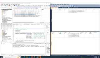
Your example can code is running but not read can module data. I attached screen shot below:

I have use for AM62B-P HS-FS' external can module is working for in linux terminal working fine. I attached screen shot below:

I want to read can module in ccs code(I want bare metal code) so help me. I have use for mcu_plus_sdk_am62x_09_01_00_39. 

Regards,

Veerapandiyan V.

  • Hi Veerapandiyan,

    Please help us understand your requirement in a bit more detail so that I can help you better.
    Are you looking for an internal loopback MCAN test or an external one?

    The Polling example that you have shared is an internal loopback example.

    How are you sending over the data that is expected to be read?

    Regards,
    Aparna

  • Hi Aparna,

    I used for external can Transceiver (SN65HVD230) using 250kbps baud rate. I connect the MCAN1 how to read external can module data.

    I checked interrupt loopback code always working for internnal, I attached screen shot below:

    Regards,

    Veerapandiyan V.

  • Hi,

    Thanks for the information!

    Are you planning to send the data from PC(via SN65HVD230) to the EVM and read it on the console?

    Currently, we don't have MCAN external loopback examples supported with our SDKs.

    Please refer to AM64x external loopback examples to enable any software changes required for your setup.

    https://www.ti.com/tool/download/MCU-PLUS-SDK-AM64X/09.01.00.41

    https://software-dl.ti.com/mcu-plus-sdk/esd/AM64X/09_01_00_41/exports/docs/api_guide_am64x/EXAMPLES_DRIVERS_MCAN_EXTERNAL_LOOPBACK_INTERRUPT.html


    Regards,
    Aparna

  • Hi Aparna,

    AM64x mcu+sdk only show for R5 core. I want to M4F core. So i add mcan_transceiver.c file is adding for m4f core is coming error is I2C.
    I enable the I2C again different error is came, So I want to M4F core based  other reference file send me.

    Regards,

    Veerapandiyan V.

  • Hi Veerapandiyan,

    Could you share the error logs and more detail about the procedure you are following to enable MCAN test on M4?

    Regards,
    Aparna

  • Hi Aparna,

    I solved error but debug time come some error msg how to fix attached below

    [BLAZAR_Cortex_M4F_1] ERROR: Drivers_i2cOpen:86: I2C open failed for instance 0 !!!
    ERROR: Drivers_uartOpen:168: UART open failed for instance 0 !!!
    ASSERT: 0.3767s: ../mcan_transceiver.c:SetupI2CTransfer:107: SystemP_SUCCESS == status failed !!!

    I  add this two files correct or not tell i attached below screen shot

    mcan_loopback_interrupt.c this file i edit for Drivers_open(); and Board_driversOpen(); this line hide mean uart error not came, only came for this error ASSERT: 0.3767s: ../mcan_transceiver.c:SetupI2CTransfer:107: SystemP_SUCCESS == status failed !!!

    Another one doubt mcan need for i2c please tell.

    Regards,

    Veerapandiyan V.

  • Hi Veerapandiyan, 

    What are your hardware connections? What MCAN and I2C instances are in use?

    Regards,
    Aparna

  • Hi Aparna,

    I have use for Arduino and AM62B-P board. Arduino transmitter using MCP2515, receiver side i use for AM62B-P board interface Transceiver (SN65HVD230) using 250kbps baud rate.

    video is connected for brown and green wire is wrong. I change the hardware. All other pin's are correct

    pinout 

    AM62X==>pin no 1 3.3v ==> SN65HVD230 ==> 3.3v (Brown)

    AM62X==>pin no 1 3.3v ==> SN65HVD230 ==> Gnd (Green)

    AM62X==>pin no 16 MCU_MCAN0_TX ==> SN65HVD230 ==> CAN TX (Brown)

    AM62X==>pin no 22 MCU_MCAN0_RX ==> SN65HVD230 ==> CAN RX (Red)

    Hardware connection Image and Video below:

    Image:

    Video:

    how to solve please tell.

    Regards,

    Veerapandiyan V.

  • Hi Veerapandiyan,

    Thanks for sharing the details!

    The hardware connections looks correct.

    Can you also share the syscfg file that is created for this project?

    Regards,
    Aparna

  • Hi Aparna,

    I am attaching the syscfg  files for I2C, UART and MCAN.

    I2C image:

    MCAN Image:

    MCAN Global Parameters:

    UART I mage:

    Any correction please tell me.

    Regards,

    Veerapandiyan V.

  • Hi Veerapandiyan,

    Can you try running the example without mcan_enableTransceiver()?

    And then debug via CCS to understand where the failure occurs.

    Regards,
    Aparna

  • Hi Aparna,

    I checked and screen record my output below i attached the file

    ccs checking video Link: drive.google.com/.../view

    I upload video link for terminal output is AM62x GP board, AM62B-P board also same error is came.

    Terminal output Video Link : https://drive.google.com/file/d/1QgOrn6M-yMbvtdefThpuW510mzohtAa7/view?usp=sharing

    pinout image:

    how to solve this problem please tell me.

    Regards,

    Veerapandiyan V.

  • Hi Veerapandiyan,

    Thanks for sharing the outputs.

    As already mentioned external loopback feature is not supported on MCU+ SDK.
    I will update you if there is any workaround to enable this functionality.

    Regards,
    Aparna

  • Hi Aparna,

    I have one doubt ccs studio not editable for effective data bit rate column 2 is there.  I attached screen shot below:


    how to fix this issue. I checked all ti mcan questions not solved for M4F, all the answer is working Linux. which version board support m4f can external transceiver tell me.

    Regards,

    Veerapandiyan V.

  • Hi Veerapandiyan,

    Bitrates and sampling point are calculated using the following formulae:

    bit rate(bits per second) = (CAN clock in Hz) / BRP / (1 + TSEG1 + TSEG2)
    Sampling Point(%) = (1 + TSEG1) / (1 + TSEG1 + TSEG2)

    (Note: Values selected in Sysconfig / the values set in structure are directly programmed in MCAN register bit fields. The actual interpretation by the hardware of this value is such that one more than the value programmed.)

    For example:

    Default values used for NOM bit rate are
    MCAN_BitTimingParams::nomRatePrescalar = 7 (BRP = 8)
    MCAN_BitTimingParams::nomTimeSeg1 = 12 (TSEG1 = 13)
    MCAN_BitTimingParams::nomTimeSeg2 = 5 (TSEG2 = 6)
    bit rate = 80MHz / 8 / (1 + 13 + 6) = 0.5 Mbps

    Note: Make sure to also calculate the sampling points in a similar manner and set it on your host side. If all parameters are not set correctly, there will be no acknowledge of data transmission from the host and transfer of data will fail.

    Regards,
    Aparna
  • Hi,

    The mcan config template file didn't contain the code to convert the decimal value to hex value. Hence the MCAN parameters might give out wrong values.
    Please update the mcan_config.c.xdt file with the below code. 

    %%{
        let module = system.modules['/drivers/mcan/mcan'];
    %%}
    /*
     * MCAN
     */
    /* MCASP Default Bit timing Parameters */
    MCAN_BitTimingParams gMcanBitTimingDefaultParams =
    {
        .nomRatePrescalar   = 0x`module.$static.nomRatePrescalar.toString(16).toUpperCase()`U,
        .nomTimeSeg1        = 0x`module.$static.nomTimeSeg1.toString(16).toUpperCase()`U,
        .nomTimeSeg2        = 0x`module.$static.nomTimeSeg2.toString(16).toUpperCase()`U,
        .nomSynchJumpWidth  = 0x`module.$static.nomSynchJumpWidth.toString(16).toUpperCase()`U,
        .dataRatePrescalar  = 0x`module.$static.dataRatePrescalar.toString(16).toUpperCase()`U,
        .dataTimeSeg1       = 0x`module.$static.dataTimeSeg1.toString(16).toUpperCase()`U,
        .dataTimeSeg2       = 0x`module.$static.dataTimeSeg2.toString(16).toUpperCase()`U,
        .dataSynchJumpWidth = 0x`module.$static.dataSynchJumpWidth.toString(16).toUpperCase()`U,
    };


    The mcan_config.c.xdt file is located at path {MCU+SDK}/source/drivers/.meta/mcan/templates. After updating the file restart the sysconfig tool and it will work fine.

    Please let me know if this solution works for you.

    Thanks & Regards,
    Aparna

  • Hi Aparna,

     Already same settings is there. I use 500kbps bitrate 8mhz oscilator how to apply this value in ccs code tell me.

    Regards,

    Veerapandiyan V.

  • Have you also set the sampling point correctly?

    What is the reason for you to set it at this exact bitrate 500 kbps?
    You can use the above formula to make combinations and get it.

    Regards,
    Aparna

  • Hi Aparna,

    One more doubt two effective data bit rate is which one i edit 1st one or 2nd tell me.

    Regards,

    Veerapandiyan V.

  • Hi Aparna,

    I changed bitrate also but not working how to fix attach below image

    Regards,

    Veerapandiyan V.

  • Are you trying to send data from external source and receive it on TI EVM?

    If yes, what tools are you using to using to send the data (both hardware and software)?

    Regards,
    Aparna

  • Hi Aparna,

    I have use for Arduino and AM62B-P board. Arduino transmitter using MCP2515, receiver side i use for AM62B-P board interface Transceiver (SN65HVD230) using 500kbps baud rate.

    video is connected for brown and green wire is wrong. I change the hardware. All other pin's are correct

    pinout 

    AM62X==>pin no 1 3.3v ==> SN65HVD230 ==> 3.3v (Brown)

    AM62X==>pin no 1 3.3v ==> SN65HVD230 ==> Gnd (Green)

    AM62X==>pin no 16 MCU_MCAN0_TX ==> SN65HVD230 ==> CAN TX (Brown)

    AM62X==>pin no 22 MCU_MCAN0_RX ==> SN65HVD230 ==> CAN RX (Red)

    Hardware connection Image and Video below:

    Image:

    Video:

    Regards,

    Veerapandiyan V.

  • Could you share Arduino transmitter code ?

    Are you using standard CAN 8 bytes data length?
    The application code sets CAN FD data format which is 64 bytes.
    In the CAN FD format, the Data length coding differs from the standard CAN.


    Could you try the following:

    1) In your application code, remove mcan_enableTransceiver() function (This is not needed if external transceiver is connected.)
    2) In your application code, make sure App_mcanConfig(FALSE) function has FALSE bool parameter passed (This will enable external loopback to work)
    3) Parse 64 bytes data from Arduino transmitter.


    Regards,
    Aparna

  • Hi Aparna,

    Which file use AM62x MCU+SDK or AM64x MCU+SDK.

    1. I use AM64x send FALSE argument it,s came error

    Building file: "../mcan_rx_only_interrupt.c"
    Invoking: Arm Compiler
    "/home/bpt/ti/ti-cgt-armllvm_3.2.0.LTS/bin/tiarmclang" -c -mcpu=cortex-m4 -mfloat-abi=hard -mlittle-endian -mthumb -I"/home/bpt/ti/ti-cgt-armllvm_3.2.0.LTS/include/c" -I"/home/bpt/ti/mcu_plus_sdk_am62x_09_01_00_39/source" -DSOC_AM62X -DUSE_8MHZ_XTAL -D_DEBUG_=1 -g -Wall -Wno-gnu-variable-sized-type-not-at-end -Wno-unused-function -MMD -MP -MF"mcan_rx_only_interrupt.d_raw" -MT"mcan_rx_only_interrupt.o" -I"/home/bpt/workspace_v09.01/mcan_loopback_interrupt_am62x-sk_m4fss0-0_nortos_ti-arm-clang/Debug/syscfg"   -o"mcan_rx_only_interrupt.o" "../mcan_rx_only_interrupt.c"
    subdir_rules.mk:35: recipe for target 'mcan_rx_only_interrupt.o' failed
    ../mcan_rx_only_interrupt.c:147:5: warning: call to undeclared function 'IpcNotify_syncAll'; ISO C99 and later do not support implicit function declarations [-Wimplicit-function-declaration]
        IpcNotify_syncAll(SystemP_WAIT_FOREVER);
        ^
    ../mcan_rx_only_interrupt.c:169:24: error: too many arguments to function call, expected 0, have 1
        App_mcanEnableIntr(FALSE);
        ~~~~~~~~~~~~~~~~~~ ^~~~~
    /home/bpt/ti/mcu_plus_sdk_am62x_09_01_00_39/source/drivers/hw_include/tistdtypes.h:107:16: note: expanded from macro 'FALSE'
    #define FALSE           ((Bool) 0)
                            ^~~~~~~~~~
    ../mcan_rx_only_interrupt.c:121:16: note: 'App_mcanEnableIntr' declared here
    static void    App_mcanEnableIntr(void);
                   ^
    1 warning and 1 error generated.
    gmake: *** [mcan_rx_only_interrupt.o] Error 1
    Building file: "syscfg/ti_board_open_close.c"
    Invoking: Arm Compiler
    "/home/bpt/ti/ti-cgt-armllvm_3.2.0.LTS/bin/tiarmclang" -c -mcpu=cortex-m4 -mfloat-abi=hard -mlittle-endian -mthumb -I"/home/bpt/ti/ti-cgt-armllvm_3.2.0.LTS/include/c" -I"/home/bpt/ti/mcu_plus_sdk_am62x_09_01_00_39/source" -DSOC_AM62X -DUSE_8MHZ_XTAL -D_DEBUG_=1 -g -Wall -Wno-gnu-variable-sized-type-not-at-end -Wno-unused-function -MMD -MP -MF"syscfg/ti_board_open_close.d_raw" -MT"syscfg/ti_board_open_close.o" -I"/home/bpt/workspace_v09.01/mcan_loopback_interrupt_am62x-sk_m4fss0-0_nortos_ti-arm-clang/Debug/syscfg"   -o"syscfg/ti_board_open_close.o" "syscfg/ti_board_open_close.c"
    Finished building: "syscfg/ti_board_open_close.c"
     
    Building file: "../main.c"
    Invoking: Arm Compiler
    "/home/bpt/ti/ti-cgt-armllvm_3.2.0.LTS/bin/tiarmclang" -c -mcpu=cortex-m4 -mfloat-abi=hard -mlittle-endian -mthumb -I"/home/bpt/ti/ti-cgt-armllvm_3.2.0.LTS/include/c" -I"/home/bpt/ti/mcu_plus_sdk_am62x_09_01_00_39/source" -DSOC_AM62X -DUSE_8MHZ_XTAL -D_DEBUG_=1 -g -Wall -Wno-gnu-variable-sized-type-not-at-end -Wno-unused-function -MMD -MP -MF"main.d_raw" -MT"main.o" -I"/home/bpt/workspace_v09.01/mcan_loopback_interrupt_am62x-sk_m4fss0-0_nortos_ti-arm-clang/Debug/syscfg"   -o"main.o" "../main.c"
    Finished building: "../main.c"
     
    gmake: Target 'all' not remade because of errors.
    
    **** Build Finished ****
    

    2.Use AM62x loopback polling method build no error but not came output. I use same configuration file

    How to solve this problem.

    Regards,

    Veerapandiyan V.

  • Hi Veerapandiyan,

    You can use AM62X internal loopback application as well. 
    Make this change in the example code: 

    In your application code, make sure App_mcanConfig(FALSE) function has FALSE bool parameter passed and then build your example. (This will enable external loopback to work)

    Regards,
    Aparna

  • Hi Aparna,

    I used for AM62x loopback code is not working. I attached video record link below:

    drive.google.com/.../view

    Arduino transmit code:

    // CAN Send Example
    //
    
    #include <mcp_can.h>
    #include <SPI.h>
    
    MCP_CAN CAN0(10);     // Set CS to pin 10
    
    void setup()
    {
      Serial.begin(115200);
    
      // Initialize MCP2515 running at 16MHz with a baudrate of 500kb/s and the masks and filters disabled.
      if(CAN0.begin(MCP_ANY, CAN_500KBPS, MCP_8MHZ) == CAN_OK) Serial.println("MCP2515 Initialized Successfully!");
      else Serial.println("Error Initializing MCP2515...");
    
      CAN0.setMode(MCP_NORMAL);   // Change to normal mode to allow messages to be transmitted
    }
    
    byte data[8] = {0x0A, 0x0B, 0x0C, 0x0D, 0x0E, 0x0F, 0x0A, 0x0B};
    
    void loop()
    {
      // send data:  ID = 0x100, Standard CAN Frame, Data length = 8 bytes, 'data' = array of data bytes to send
      byte sndStat = CAN0.sendMsgBuf(0x18FFA2F4, 1, 8, data);
      if(sndStat == CAN_OK){
        Serial.println("Message Sent Successfully!");
      } else {
        Serial.println("Error Sending Message...");
      }
      delay(100);   // send data per 100ms
    }
    
    /*********************************************************************************************************
      END FILE
    *********************************************************************************************************/

    Interrupt code also cheking same output only

    How to fix this problem.

    Regards,

    Veerapandiyan V.

  • Hi Veerapandiyan, 

    Do you have a PCAN module to test the working of MCAN ?

    It will be more convenient to carve out Arduino setup compatibility with the MCAN transceiver you are using currently.

    Regards,
    Aparna 

  • Hi Aparna

    We are having MCAN currently and dont have PCAN, as of now we are working with MCAN, Arduino and Sitara setup. 

    Thanks 

    Veerapandiyan 

  • Hi Aparna,

    Any Update. I am waiting for your reply. I want for can dump code.

    Thanks

    Veerapandiyan V.

  • Hi Veerapandiyan, 

    I have tried the external loopback with my setup, with the changes I had shared earlier, and it works for me. So, looks like the issue is related to the hardware configurations of your setup. Can you also try sending data from EVM and make Arduino as receiving end, see if you can get data at the other end?

    The application code sends out the data first, waits for an acknowledgement and then receives the data, so it might be possible in your case that code is still stuck in TX semaphore, and hence unable to go further to recieve data.

    Regards,
    Aparna

  • Hi Aparna,

    My code working for A53 core is perfect working M4F only not working. So you send your working code this mail Id veerapandiyan@etanamobility.com i will check. Then you send your working can output screenshot and your hardware images also. I will check my side.

    Regards,

    Veerapandiyan

  • Hi Aparna,

    I will check different testing.

    1. A53 i mismatch the bit rate MCAN RX is not working Arduino serial monitor also show for error sending message attached image below:

    2. A53 is match the bit rate MCAN RX is working Arduino serial monitor also show for sending message successfully attached image below:

    3. I am debug the M4F core not press play icon show error sending message attached image below:

    4. I am debug the M4F core press play icon show sending message successfully attached image below:

    5.I will check MCAN TX RX pin state is getting:

    RX: MCAN 1 RX PIN STATE =  1

    TX: MCAN 1 TX PIN STATE =  0

    I will check document Transmitter pin only enable, Receive pin is disble how to fix the problem. I need for only read how to change settings tell me.

    Regards,

    Veerapandiyan.

  • Hi Veerapandiyan,

    Could you comment out the following section of code, which is TX related, re-build the project and try again?

            /* Configure Tx Msg to transmit */
            App_mcanConfigTxMsg(&txMsg);
    
            /* Select buffer number, 32 buffers available */
            bufNum = 0U;
            /* Enable Transmission interrupt for the selected buf num,
             * If FIFO is used, then need to send FIFO start index until FIFO count */
            status = MCAN_txBufTransIntrEnable(gMcanBaseAddr, bufNum, (uint32_t)TRUE);
            DebugP_assert(status == CSL_PASS);
    
            /* Write message to Msg RAM */
            MCAN_writeMsgRam(gMcanBaseAddr, MCAN_MEM_TYPE_BUF, bufNum, &txMsg);
    
            /* Add request for transmission, This function will trigger transmission */
            status = MCAN_txBufAddReq(gMcanBaseAddr, bufNum);
            DebugP_assert(status == CSL_PASS);
    
            /* Wait for Tx completion */
            SemaphoreP_pend(&gMcanTxDoneSem, SystemP_WAIT_FOREVER);
    
            MCAN_getProtocolStatus(gMcanBaseAddr, &protStatus);
            /* Checking for Tx Errors */
            if (((MCAN_ERR_CODE_NO_ERROR != protStatus.lastErrCode) ||
                 (MCAN_ERR_CODE_NO_CHANGE != protStatus.lastErrCode)) &&
                ((MCAN_ERR_CODE_NO_ERROR != protStatus.dlec) ||
                 (MCAN_ERR_CODE_NO_CHANGE != protStatus.dlec)) &&
                (0U != protStatus.pxe))
            {
                 DebugP_assert(FALSE);
            }


    Also, how are you printing the RX and TX pin state?

    Regards,
    Aparna

  • Hi Aparna, 

    I already tried Tx code hide and Rx code only checking that time only show for this pin state value. I attached Rx code check and tell:

    /* Poll for Rx completion */
            fifoStatus.num = MCAN_RX_FIFO_NUM_0;
            do
            {
                fifoFillLvl = MCAN_getRxPinState(gMcanBaseAddr);
                DebugP_log("MCAN 1 RX PIN STATE =  %d\r\n",fifoFillLvl);
                fifoFillLvl = MCAN_getTxPinState(gMcanBaseAddr);
                DebugP_log("MCAN 1 TX PIN STATE =  %d\r\n",fifoFillLvl);
    
                MCAN_getRxFIFOStatus(gMcanBaseAddr, &fifoStatus);
                fifoFillLvl = fifoStatus.fillLvl;
                DebugP_log("MCAN 1 FIFO STATE =  %d\r\n",fifoFillLvl);
            }while(fifoFillLvl != APP_MCAN_FIFO_0_CNT);
            for(loopCnt = 0U ; loopCnt < fifoFillLvl ; loopCnt++)
            {
                /* Checking for Rx Errors */
                MCAN_getErrCounters(gMcanBaseAddr, &errCounter);
                DebugP_assert((0U == errCounter.recErrCnt) &&
                              (0U == errCounter.canErrLogCnt));
    
                MCAN_getRxFIFOStatus(gMcanBaseAddr, &fifoStatus);
                MCAN_readMsgRam(gMcanBaseAddr, MCAN_MEM_TYPE_FIFO, fifoStatus.getIdx,
                                fifoStatus.num, &rxMsg);
               (void) MCAN_writeRxFIFOAck(gMcanBaseAddr, fifoStatus.num,
                                          fifoStatus.getIdx);

    fifoFillLvl = MCAN_getRxPinState(gMcanBaseAddr);
    DebugP_log("MCAN 1 RX PIN STATE = %d\r\n",fifoFillLvl);
    fifoFillLvl = MCAN_getTxPinState(gMcanBaseAddr);
    DebugP_log("MCAN 1 TX PIN STATE = %d\r\n",fifoFillLvl); 

    This two lines added for Rx part only i checked Tx and Rx pin state.

    please send your hardware image and code also send mail. your nominal bitrate and data bitrate tell me.

    My code working for A53 core is perfect working M4F only not working. So you send your working code this mail Id veerapandiyan@etanamobility.com i will check. Then you send your working can output screenshot and your hardware images also. I will check my side.

    Regards,

    Veerapandiyan.

  • Hi Veerapandiyan,

    I will check with the team regarding pin state, where its going recessive and how to enable it to recieve data.

    Meanwhile can you make sure TX pin is working fine by transmitting data from EVM and receiving it on the other end?

    I will send my code and setup information via email by EOD.

    Regards,
    Aparna

  • Hi Aparna

    The TX pin is working fine, we are able to read the data transmitted on the other side. Please do the needful regarding the RX pin. I attached image below:

    Thanks

    Veerapandiyan

  • Hi Aparna

    Any Update. I am waiting for your reply.

    Thanks

    Veerapandiyan

  • Hi, 

    I have tested this on AM62A, and I am attaching the code, hardware setup images and output images below.

    Reference code:
    empty_am62ax-sk_mcu-r5fss0-0_freertos_ti-arm-clang.zip

    Hardware image:


    Output: 


    Regards,
    Aparna

  • Hi Aparna

    Its great to hear back from you, but the problem is 

    1. We are using AM62B-P HS-FS board. ( as i can see in the image you are using a different board ). 

    2.  I am currently using TI - Processor ti-processor-sdk-linux-am62xx-evm-09.00.00.03 and MCU + SDK mcu_plus_sdk_am62x_09_01_00_39 ( and i can see that you are using ( ti.MCU_PLUS_SDK_AM62AX v8.6.0.18 )

    i am attaching the error for your reference, please do look into this. 

    thanks 

    Veerapandiayan

  • Hi Veerapandiayan, 

    You cannot use this example directly, but you can copy the content of mcan_tx_only_interrupt.c into mcan_loopback_interrupt.c 
    Also, use the function i.e. mcan_external_read_write_main() in main.c

    Let me know if this works.

    Regards, 
    Aparna

  • Hi Aparna,

    I changed to mcan_loopback_interrupt.c file compile is done but not transmitting data bitrate also same 1000kbps but not transmitting data. I attached screenshot below:

    changed to mcan_loopback_polling.c file compile is done but not transmitting data bitrate also same 1000kbps but not transmitting data. I attached screenshot below:

    previous mcu+sdk example code also tranmitting working fine but this code not working transmit. How to solve this problem.

    Thanks,

    Veerapandiyan V.


  • Can you tell where does the code fail to 
    work?
    You can add a breakpoint and check this. 

    Regards,
    Aparna

  • Hi Aparna 

    I am getting the error in this line only , while i checked with breakpoints

    /* Wait for Tx completion */
    SemaphoreP_pend(&gMcanTxDoneSem, SystemP_WAIT_FOREVER);


    Regards,

    Veerapandiyan

  • Hi Veerapandiyan, 

    Can you reset the board and try again?

    This error indicates, the bit timing parameters of the sender and receiver DONOT match. 
    The bit rates and sampling points are important to establish connection. 
    I do not see any sampling point setting parameter in your Arduino code. Can you figure out a way to do this?

    Regards,
    Aparna

  • Hi Aparna,

     I reset the board agian try it's came same line error only. I attached the Arduino send and recive code file then Global ParametersSettings that affect all instances attach screenshot.

    Arduino send and receive code:

    // CAN Receive Example
    //
    
    #include <mcp_can.h>
    #include <SPI.h>
    
    long unsigned int rxId,a=0,j=0;
    unsigned char len = 0;
    unsigned char rxBuf[8];
    char msgString[128];                        // Array to store serial string
    
    #define CAN0_INT 2                              // Set INT to pin 2
    MCP_CAN CAN0(10);                               // Set CS to pin 10
    
    byte data[8] = {0xAa, 0x0B, 0x0C, 0x0D, 0x0E, 0x0F, 0x0A, 0x0B};
    void setup()
    {
      Serial.begin(115200);
      
      // Initialize MCP2515 running at 16MHz with a baudrate of 500kb/s and the masks and filters disabled.
      if(CAN0.begin(MCP_ANY, CAN_1000KBPS, MCP_8MHZ) == CAN_OK)
        Serial.println("MCP2515 Initialized Successfully!");
      else
        Serial.println("Error Initializing MCP2515...");
      
      CAN0.setMode(MCP_NORMAL);                     // Set operation mode to normal so the MCP2515 sends acks to received data.
    
      pinMode(CAN0_INT, INPUT);                            // Configuring pin for /INT input
      
      Serial.println("MCP2515 Library Receive Example...");
    }
    
    void loop()
    {
      if(!digitalRead(CAN0_INT))                         // If CAN0_INT pin is low, read receive buffer
      {
        CAN0.readMsgBuf(&rxId, &len, rxBuf);      // Read data: len = data length, buf = data byte(s)
        
        if((rxId & 0x80000000) == 0x80000000)     // Determine if ID is standard (11 bits) or extended (29 bits)
          sprintf(msgString, "Extended ID: 0x%.8lX  DLC: %1d  Data:", (rxId & 0x1FFFFFFF), len);
        else
          sprintf(msgString, "Standard ID: 0x%.3lX       DLC: %1d  Data:", rxId, len);
      
        Serial.print(msgString);
      
        if((rxId & 0x40000000) == 0x40000000){    // Determine if message is a remote request frame.
          sprintf(msgString, " REMOTE REQUEST FRAME");
          Serial.print(msgString);
        } else {
          for(byte i = 0; i<len; i++){
            sprintf(msgString, " 0x%.2X", rxBuf[i]);
            Serial.print(msgString);
            j=0;
          }
          a=a+1;
          Serial.print(a);
        }  
        Serial.println();
    
      }
      if(a>=4)
      {
        for(j=0;j<=3;j++)
        {
        // send data:  ID = 0x100, Standard CAN Frame, Data length = 8 bytes, 'data' = array of data bytes to send
      byte sndStat = CAN0.sendMsgBuf(0x18FFA2F4, 1, 8, data);
      if(sndStat == CAN_OK){
        Serial.println("Message Sent Successfully!");
      } else {
        Serial.println("Error Sending Message...");
      }
      delay(100);   // send data per 100ms
      a=0;
      }
      }
    }
    
    /*********************************************************************************************************
      END FILE
    *********************************************************************************************************/
    

    Global parameters

    Arduino i am using 1000kbps.

    Regards,

    Veerapandiyan

  • Hi Aparna,

     I reset the board agian try it's came same line error only. I attached the Arduino send and recive code file then Global ParametersSettings that affect all instances attach screenshot.

    Arduino send and receive code:

    // CAN Receive Example
    //
    
    #include <mcp_can.h>
    #include <SPI.h>
    
    long unsigned int rxId,a=0,j=0;
    unsigned char len = 0;
    unsigned char rxBuf[8];
    char msgString[128];                        // Array to store serial string
    
    #define CAN0_INT 2                              // Set INT to pin 2
    MCP_CAN CAN0(10);                               // Set CS to pin 10
    
    byte data[8] = {0xAa, 0x0B, 0x0C, 0x0D, 0x0E, 0x0F, 0x0A, 0x0B};
    void setup()
    {
      Serial.begin(115200);
      
      // Initialize MCP2515 running at 16MHz with a baudrate of 500kb/s and the masks and filters disabled.
      if(CAN0.begin(MCP_ANY, CAN_1000KBPS, MCP_8MHZ) == CAN_OK)
        Serial.println("MCP2515 Initialized Successfully!");
      else
        Serial.println("Error Initializing MCP2515...");
      
      CAN0.setMode(MCP_NORMAL);                     // Set operation mode to normal so the MCP2515 sends acks to received data.
    
      pinMode(CAN0_INT, INPUT);                            // Configuring pin for /INT input
      
      Serial.println("MCP2515 Library Receive Example...");
    }
    
    void loop()
    {
      if(!digitalRead(CAN0_INT))                         // If CAN0_INT pin is low, read receive buffer
      {
        CAN0.readMsgBuf(&rxId, &len, rxBuf);      // Read data: len = data length, buf = data byte(s)
        
        if((rxId & 0x80000000) == 0x80000000)     // Determine if ID is standard (11 bits) or extended (29 bits)
          sprintf(msgString, "Extended ID: 0x%.8lX  DLC: %1d  Data:", (rxId & 0x1FFFFFFF), len);
        else
          sprintf(msgString, "Standard ID: 0x%.3lX       DLC: %1d  Data:", rxId, len);
      
        Serial.print(msgString);
      
        if((rxId & 0x40000000) == 0x40000000){    // Determine if message is a remote request frame.
          sprintf(msgString, " REMOTE REQUEST FRAME");
          Serial.print(msgString);
        } else {
          for(byte i = 0; i<len; i++){
            sprintf(msgString, " 0x%.2X", rxBuf[i]);
            Serial.print(msgString);
            j=0;
          }
          a=a+1;
          Serial.print(a);
        }  
        Serial.println();
    
      }
      if(a>=4)
      {
        for(j=0;j<=3;j++)
        {
        // send data:  ID = 0x100, Standard CAN Frame, Data length = 8 bytes, 'data' = array of data bytes to send
      byte sndStat = CAN0.sendMsgBuf(0x18FFA2F4, 1, 8, data);
      if(sndStat == CAN_OK){
        Serial.println("Message Sent Successfully!");
      } else {
        Serial.println("Error Sending Message...");
      }
      delay(100);   // send data per 100ms
      a=0;
      }
      }
    }
    
    /*********************************************************************************************************
      END FILE
    *********************************************************************************************************/
    

    Global parameters

    Arduino i am using 1000kbps.

    see the file:

    The TX pin is working fine, we are able to read the data transmitted on the other side. Please do the needful regarding the RX pin. I attached image below:

    Regards,

    Veerapandiyan

  • Hi Aparna,

    Any Update. I am waiting for your reply.

    Thanks

    Veerapandiyan

  • Hi Aparna, 

    Your global parameters screenshot share me.

    Regards,

    Veerapandiyan

  • Hi Veerapandiyan, 

    Here are my global parameter values:


    Apart from the Nominal bitrate and Data bitrate, I am also calculating sampling point and setting it on PCAN view software. Only then, I am able to send and receive data correctly.

    Regards,
    Aparna

  • Hi Aparna,

    Bitrates and sampling point are calculated using the following formulae:

    bit rate(bits per second) = (CAN clock in Hz) / BRP / (1 + TSEG1 + TSEG2)

    I need some clarification i am using transmitter side MCP2515 module :

    CAN Clock = 8Mhz

    Baud Rate = 500 Kbps

    how to calculate prescaler, tseg1 and tseg2.

    Regards,

    Veerapandiyan V.