Other Parts Discussed in Thread: SYSCONFIG, UNIFLASH
Hello all,
picking up on the related post:
Now that I know that configuring the DDR to MSRAM works on the EVM and I am able to flash an application in the EVM I now switched to the custom board.
On the custom board I have following configurations: I have a quad-SPI nor-flash chip (MX25U51245G). Like in the last post I adapted the linker to use the MSRAM instead of the DDR, following this guide, so I removed the DDR-Ram from the SysConfig. I also set the MMCSD-device type to NO_DEVICE.
I also patched the `flash-ospi` src under `\source\board\flash\ospi` following this guideline:
```
I configured on my custom board UART mode and tried pushing the GP image(because my custom board uses a chip with GP architecture).
The programm seems to get stuck when trying to load sbl_null:
```
C:\ti\mcu_plus_sdk_am64x_08_06_00_45\tools\boot>python uart_uniflash.py -p COM16 --cfg sbl_prebuilt/am64x-evm/default_sbl_null_tq.cfg
Parsing config file ...
Parsing config file ... SUCCESS. Found 2 command(s) !!!
Executing command 1 of 2 ...
Found flash writer ... sending sbl_prebuilt/am64x-evm/sbl_uart_uniflash_tq.tiimage
Sent flashwriter sbl_prebuilt/am64x-evm/sbl_uart_uniflash_tq.tiimage of size 314270 bytes in 29.39s.
Executing command 2 of 2 ...
Command arguments : --file=sbl_prebuilt/am64x-evm/sbl_null.release.tiimage --operation=flash --flash-offset=0x0
Sending sbl_prebuilt/am64x-evm/sbl_null.release.tiimage: 0%| | 0/271879 [00:00<?, ?bytes/s]
```
Does someone have maybe any idea of what is wrong?
I doublechecked the flash sysconfig to see if it is running. We already have an application(which I run through JTAG loading it into the MSRAM thorugh the load_dsmc.js script using CCS), which uses the same flash sysconfig and patch for the `\source\board\flash\ospi\flash_ospi.c` file. There the QSPI Test seems to work. Both configs (for the sbl and for the app that I tested the qspi) are uploaded with this issue. The one called TQMa64XxL_ALV.sysconfig is the config for the application that was tested.
Btw the test script we use is also included.
Thanks for every hint or help!!!
Isaac L. L. Yuki
/*
* Copyright (C) 2021 Texas Instruments Incorporated
*
* Copyright (c) 2022 TQ-Systems GmbH <license@tq-group.com>, D-82229 Seefeld, Germany.
* Author Michael Bernhardt
*
* Redistribution and use in source and binary forms, with or without
* modification, are permitted provided that the following conditions
* are met:
*
* Redistributions of source code must retain the above copyright
* notice, this list of conditions and the following disclaimer.
*
* Redistributions in binary form must reproduce the above copyright
* notice, this list of conditions and the following disclaimer in the
* documentation and/or other materials provided with the
* distribution.
*
* Neither the name of Texas Instruments Incorporated nor the names of
* its contributors may be used to endorse or promote products derived
* from this software without specific prior written permission.
*
* THIS SOFTWARE IS PROVIDED BY THE COPYRIGHT HOLDERS AND CONTRIBUTORS
* "AS IS" AND ANY EXPRESS OR IMPLIED WARRANTIES, INCLUDING, BUT NOT
* LIMITED TO, THE IMPLIED WARRANTIES OF MERCHANTABILITY AND FITNESS FOR
* A PARTICULAR PURPOSE ARE DISCLAIMED. IN NO EVENT SHALL THE COPYRIGHT
* OWNER OR CONTRIBUTORS BE LIABLE FOR ANY DIRECT, INDIRECT, INCIDENTAL,
* SPECIAL, EXEMPLARY, OR CONSEQUENTIAL DAMAGES (INCLUDING, BUT NOT
* LIMITED TO, PROCUREMENT OF SUBSTITUTE GOODS OR SERVICES; LOSS OF USE,
* DATA, OR PROFITS; OR BUSINESS INTERRUPTION) HOWEVER CAUSED AND ON ANY
* THEORY OF LIABILITY, WHETHER IN CONTRACT, STRICT LIABILITY, OR TORT
* (INCLUDING NEGLIGENCE OR OTHERWISE) ARISING IN ANY WAY OUT OF THE USE
* OF THIS SOFTWARE, EVEN IF ADVISED OF THE POSSIBILITY OF SUCH DAMAGE.
*/
#include <kernel/dpl/DebugP.h>
#include "ti_drivers_open_close.h"
#include "ti_board_open_close.h"
#define APP_OSPI_FLASH_OFFSET_BASE (0x200000U)
#define APP_OSPI_DATA_SIZE (2048)
uint8_t gOspiTxBuf[APP_OSPI_DATA_SIZE];
/* read buffer MUST be cache line aligned when using DMA, we aligned to 128B though 32B is enough */
uint8_t gOspiRxBuf[APP_OSPI_DATA_SIZE] __attribute__((aligned(128U)));
void ospi_flash_io_fill_buffers(void);
int32_t ospi_flash_io_compare_buffers(void);
#define OSPI_RD_DATA_CAPTURE_REG_ADD (0x0FC40010)
int32_t ospi_flash_io_main(void *args)
{
int32_t status = SystemP_SUCCESS;
uint32_t offset;
uint32_t sector, blk, page;
Flash_Attrs *flashAttrs;
/* Open Flash drivers with OSPI instance as input */
if(gFlashHandle[CONFIG_FLASH0] == NULL)
{
Drivers_ospiOpen();
status = Board_flashOpen();
}
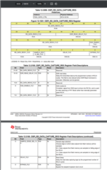
/* DELAY_FD = 2 and BYASS_FLD = enable
* The default DELAY_FD = 4 does not work with QSPI flash, so DELAY_FD = 2 must be used.
* In addition, the "board.am64x.r5f.ti-arm-clang.debug.lib" must be rebuilt with the new "flash_nor_ospi.c" file.
* Please see README.md*/
*(uint32_t*) OSPI_RD_DATA_CAPTURE_REG_ADD = 0x05;
flashAttrs = Flash_getAttrs(CONFIG_FLASH0);
/* Fill buffers with known data,
* find block number from offset,
* erase block, write the data, read back from a specific offset
* and finally compare the results.
*/
offset = APP_OSPI_FLASH_OFFSET_BASE;
ospi_flash_io_fill_buffers();
Flash_offsetToBlkPage(gFlashHandle[CONFIG_FLASH0], offset, &blk, &page);
status = Flash_eraseBlk(gFlashHandle[CONFIG_FLASH0], blk);
if(status != SystemP_SUCCESS)
{
DebugP_log("Block Erase Failed at 0x%X offset !!!", offset);
}
if(SystemP_SUCCESS == status)
{
status = Flash_write(gFlashHandle[CONFIG_FLASH0], offset, gOspiTxBuf, APP_OSPI_DATA_SIZE);
}
else
{
DebugP_log("Flash Write of %d bytes failed at 0x%X offset !!!", APP_OSPI_DATA_SIZE, offset);
}
if(SystemP_SUCCESS == status)
{
status = Flash_read(gFlashHandle[CONFIG_FLASH0], offset, gOspiRxBuf, APP_OSPI_DATA_SIZE);
}
if(SystemP_SUCCESS == status)
{
status |= ospi_flash_io_compare_buffers();
}
offset = APP_OSPI_FLASH_OFFSET_BASE + (flashAttrs->pageSize*16);
ospi_flash_io_fill_buffers();
Flash_offsetToSectorPage(gFlashHandle[CONFIG_FLASH0], offset, §or, &page);
status = Flash_eraseSector(gFlashHandle[CONFIG_FLASH0], sector);
if(status != SystemP_SUCCESS)
{
DebugP_log("Sector Erase Failed at 0x%X offset !!!", offset);
}
if(SystemP_SUCCESS == status)
{
status = Flash_write(gFlashHandle[CONFIG_FLASH0], offset, gOspiTxBuf, APP_OSPI_DATA_SIZE);
}
else
{
DebugP_log("Flash Write of %d bytes failed at 0x%X offset !!!", APP_OSPI_DATA_SIZE, offset);
}
if(SystemP_SUCCESS == status)
{
status = Flash_read(gFlashHandle[CONFIG_FLASH0], offset, gOspiRxBuf, APP_OSPI_DATA_SIZE);
}
if(SystemP_SUCCESS == status)
{
status |= ospi_flash_io_compare_buffers();
}
if(SystemP_SUCCESS == status)
{
DebugP_log("All tests have passed!!\r\n");
}
else
{
DebugP_log("Some tests have failed!!\r\n");
}
return status;
}
void ospi_flash_io_fill_buffers(void)
{
uint32_t i;
for(i = 0U; i < APP_OSPI_DATA_SIZE; i++)
{
gOspiTxBuf[i] = i % 256;
gOspiRxBuf[i] = 0U;
}
}
int32_t ospi_flash_io_compare_buffers(void)
{
int32_t status = SystemP_SUCCESS;
uint32_t i;
for(i = 0U; i < APP_OSPI_DATA_SIZE; i++)
{
if(gOspiTxBuf[i] != gOspiRxBuf[i])
{
status = SystemP_FAILURE;
DebugP_logError("OSPI read data mismatch !!!\r\n");
break;
}
}
return status;
}