Because of the holidays, TI E2E™ design support forum responses will be delayed from Dec. 25 through Jan. 2. Thank you for your patience.

This thread has been locked.

If you have a related question, please click the "Ask a related question" button in the top right corner. The newly created question will be automatically linked to this question.

Different results from EDMA

Anonymous
Anonymous
Guru 17045 points

Hi,


I would like to ask a question on EDMA on DM6437.


TI Wiki page Programming EDMA without EDMA3LLD package gave an example of configuring EDMA in the "hard manner" by modifying registers directly and I adapted the code into my DM6437 program:


Example code:
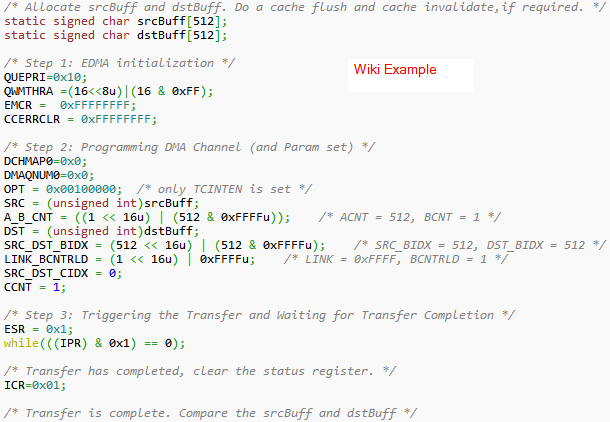


In my code,
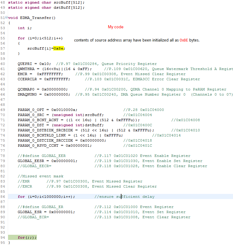


However, when executing these code turns out to have no effect, and the content of srcBuff  was not copied into dstBuff at all.


I have triple-checked register address and all of them are correct.


If instead of copying to dstBuff, I configure DMA destination to a fixed memory location, say, 0x82000000, then sometimes 0x8E would be copied to the destination array, but only for the first 4 entries; the remaining 512-4=508 entries remain unchanged. (1 )Changing 0x8E to other value, or (2) Changing destination to other fixed location, say, 0x83000000, resulted in the same that only first 4 out of 512 bytes are copied.
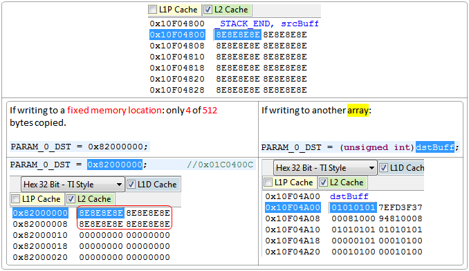


I would like to ask about:

1.    Why for fixed location destination only 4 bytes are copied?

2.    Why no copy occur when destination is set to dstBuff?

3.    Did I miss any initialization register? Since I copied the Wiki example line for line, if I missed any register(s), does it mean the Wiki article also missed the same register(s)?


Thanks,

Zheng


  • Hi Zheng,

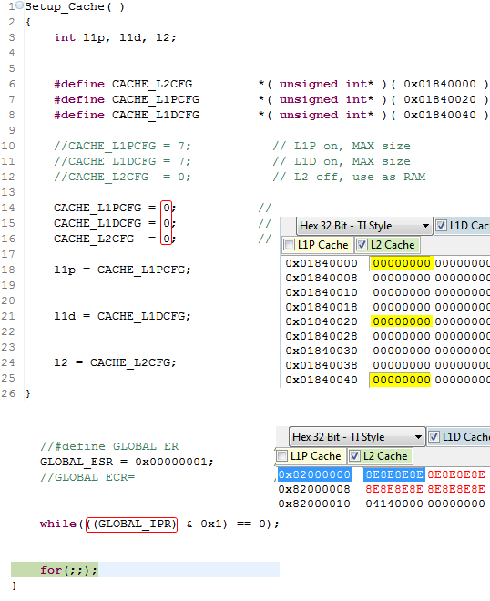
    Is Cache enable? can you turn off cache and try?

    Sometimes it can happen that, when you are writing the 0x8E to srcbuf, actually values  will be updated in cache location of srcbuf, but DMA engine reads data from actual location.

    And its better to poll 'IPR' register to check transfer completion.


    Thanks,

    Veeranna


  • Veeranna,


    I tried both of the suggestion solutions:


    1.    Disabling cache

    Done in GEL, and verified result by reading register address

    2.    Poll IPR. 

    Completion test passed.


    But still only 4 out of 512 bytes from srcBuff are copied.


    Any more suggestions?


    Zheng


  • Zheng Zhao,

    Zheng Zhao said:
    an example of configuring EDMA in the "hard manner" by modifying registers directly and I adapted the code into my DM6437 program

    What differences did you adapt for between the target device of the Wiki example and your DM6437 case?

    We do not recommend this method, in part for the very example you have presented here. You take the code example and try to move it to another processor, start changing things, and when it does not work you need help at the difficult-to-manage register level. Instead, we provide the EDMA3LLD a simple and validated path to quicker success, and we provide it ready to work with the processor that you are using so you do not have to dig into the register level for understanding how to initialize and run the EDMA3 peripheral. It does not remove you from needing to understand how transfers run, but it does remove most of the initialization and address-generation issues.

    Zheng Zhao said:
    Any more suggestions?

    Use the EDMA3LLD. Get that working, then capture the states of all of the EDMA3 registers just before starting the transfer. Run your version, capture the states of all of the EDMA3 registers just before starting the transfer, and compare the two lists for differences. Be sure to do a power cycle on the board before the test runs to capture the register values.

    Zheng Zhao said:
    Did I miss any initialization register? Since I copied the Wiki example line for line, if I missed any register(s), does it mean the Wiki article also missed the same register(s)?

    The Wiki code works. The author tested it.

    You did not copy the Wiki example line for line. Please do that (after getting the EDMA3LLD version working first), and only apply the changes needed for moving to a new processor.

    We supply the EDMA3LLD so we do not need to go through different register level code to debug it. As you stated above, this is the "hard manner" If you continue at the register level, please refer to the EDMA3 User's Guide for your processor. There is a lot to familiarize yourself with. Note the Appendix A Tips section with Debug Checklist and Debug Tips, and also note the Appendix B Setting Up a Transfer.

    Regards,
    RandyP

  • Anonymous
    0 Anonymous in reply to RandyP

    Randy,

    I am going to try your suggestions (esp. Appendix A Debug Checklist).

    One quick question:

    Does LLD require BIOS enabled project, or just need adding a few BIOS .lib files to the project? Could you also have a look at Does ACPY3 require BIOS?


    Zheng

  • Zheng.

    I do not know. The system requirements should be listed in the documentation for the software packages. If it is not, please let us know so this can be updated.

    Regards,
    RandyP

  • First off, in your param options field, you have set the DAM bit, which one : is not supported by the dm643x devices per the datasheet, and second off makes the destination address act like a FIFO, which is probably not what you want if you are complaining about the device writing to more than an 8-bit address.

  • Anonymous
    0 Anonymous in reply to MattLipsey

    Matt,

    It was indeed my mistake of setting PARAM_0_OPT.DAM as 1 (PARAM_0_OPT=0x0010 000a, rather than example's 0x00100000). I should not have made this modification when posting code which is intended to compare with the example code.

    I have changed back DAM bit to 0 now, but found that the problem still persists.

    MattLipsey said:

    and second off makes the destination address act like a FIFO, which is probably not what you want if you are complaining about the device writing to more than an 8-bit address.


    What do you mean by "makes the destination addrss act like a FIFO"? Which register and which field controls this? I am not aware that I have made this configuration.


    Zheng

  • Don't worry about the fifo.  It doesn't work for dm643x, just set those bits to 0.

    Why don't you just look at the block move example in spru987?  I haven't looked at the web example you are referencing, but I know the block move example works.  Why don't you copy the param values from that example and see if that works?

  • Anonymous
    0 Anonymous in reply to MattLipsey

    Matt,


    I did several tests just now and found the block move example worked. Thanks very much for referring me to that.

    I also confirmed that it was indeed OPT.DAM bit which caused the trouble. When this bit is set to 0-[Increment (INCR) mode], the copy works well.

    For all examples in Chapter 3, from §3.1 Block Move Example, all the way to §3.4.5 Transfer Chaining Examples, DAM bits are all cleared.


    I am curious on knowing why DAM bit is documented in spru987? I am using rev.A, the only revision available from TI.com, and its title is "TMS320DM643x DMP Enhanced DMA (EDMA) Controller User's Guide (Rev. A)", which obviously suggest that it applies to DM6437. If so, why do you say DAM bit is "not supported by the dm643x devices per the datasheet"?

    In fact, the 4 words/16 bytes copy seems to be the result of the destination address "wrapping" behavior controlled by DAM bit. The document says it wraps upon reaching FIFO width, and that FIFO bit is controlled by OPT.FWID bit. The wrapping behavior can be seen from the table below, however, I haven't found out a clear formula for how FWID bit controls wrap length exactly.


    Zheng

  • Zheng Zhao said:
    why do you say DAM bit is "not supported by the dm643x devices per the datasheet"?

    If you search the EDMA3 UG for "constant addressing mode", you will find it says this mode may not be supported in all cases and to check the data manual (datasheet). If you search the DM6437 datasheet for "constant addressing mode", you will find it says this mode is not supported on the DM6437.

    If we implement a new peripheral on a new DM643x family device, and that peripheral does support the "constant addressing mode", then we do not have to re-write the EDMA3 User's Guide for that one family member.

    Is this an acceptable answer for you?

    Regards,
    RandyP


    If you need more help, please reply back. If Matt answered the question, please click  Verify Answer  on his post.

  • Anonymous
    0 Anonymous in reply to RandyP

    Randy,


    I searched the two manuals and found the paragraph you referred to, many thanks for this clarification.


    This is certainly a good answer.


    Zheng