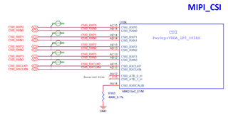
HI!TI experts.
After enabling MIPI CSI, AM625x cannot capture any images. CLK, RX0, and RX1 all have waveforms, but the waveform of CLK is not very normal, and the waveform is abnormal during the LP to HS mode stage.
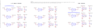
The following is CLK signal analysis:
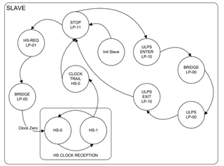
According to the protocol, DPHY enters HS mode from LP, passes through LP11, LP01, and LP00, and then enters the T-CLK-ZERO stage. At this time, CLK-N is 100mV and CLK-P is 300mV.
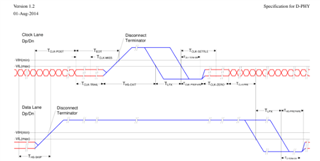
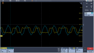
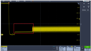
The signals of CLK-N and CLK-P in the normal drawing board meet the protocol requirements. During the T-CLK-ZERO stage, CLK-N is 100mV and CLK-P is 300mV:
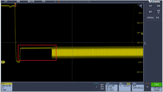
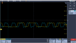
Under abnormal circumstances, the signals of CLK-N and CLK-P are as follows, and the signals of CLK-N and CLK-P in the T-CLK-ZERO stage are both incorrect.
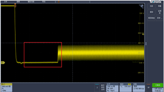
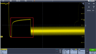
Expanding the CLK waveform reveals a normal board with a waveform close to a square wave and an amplitude that meets the requirements; Abnormal board with waveform close to sine and high amplitude.