This thread has been locked.

If you have a related question, please click the "Ask a related question" button in the top right corner. The newly created question will be automatically linked to this question.

AM6422: Is it possible to select EXT_REFCLK1 PIn via the devtree for am65-cpts?

Part Number: AM6422
Other Parts Discussed in Thread: CLOCKTREETOOL, SK-AM64B, TMDS64EVM,

I am working on a CPST driver customisation for the AM642.
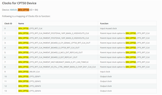
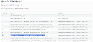
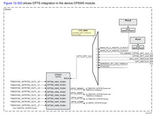
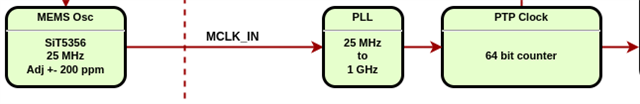
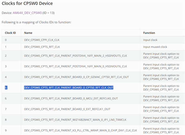
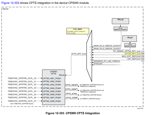
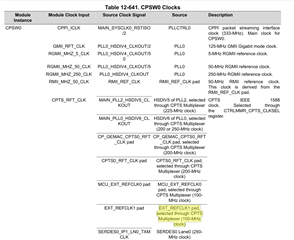
I want to use the EXT_REFCLK1 pin as source for the cpts_rft_clk via the CTRLMMR_CPTS_CLKSEL register. According to the documentation it should work and also with the CLOCKTREETOOL it seems to be possible. Please correct me if this is wrong. The idea behind this is to use the clock on EXT_REFCLK1 for PTP synchronisation.
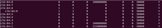
With devmen2 I can set it to the desired value.
Now I have looked in linux -Code (diver/net/ethernet/ti/am65-cpts.c and devtree for a support for this but unfortunately not found. Now my question, have I overlooked this and is there an easy way and what is the recommended way?

Thanks and best regards

  • Hello Mario,

    Are you implementing this on a custom board or the AM62x EVM (TMDS64EVM) or SK-AM64B?

    ------------------------------------------------------------------------------------------------------------------------------------------

    According to the following section of the default "k3-am64-main.dtsi", 

    • the 84 comes from the device ID of "DEV_CPTS0"
    • the 0 comes from the clock ID of "DEV_CPTS0_CPTS_RFT_CLK" 
    • the 8 comes from the clock ID of selected clock parent input clock to "DEV_CPTS0_CPTS_RFT_CLK" -----> "DEV_CPTS0_CPTS_RFT_CLK_PARENT_K3_PLL_CTRL_WRAP_MAIN_0_CHIP_DIV1_CLK_CLK" 
      • --> see "assigned-clock-parents = <&k3_clks 84 8>;"

    I obtained this information from https://downloads.ti.com/tisci/esd/latest/5_soc_doc/am64x/clocks.html#clocks-for-cpts0-device and using https://e2e.ti.com/support/processors-group/processors/f/processors-forum/1049800/faq-pru_icssg-how-to-check-and-set-pru-core-frequency-in-linux as reference for how the device tree defines the clock properties. I highly recommend reviewing section "Multiple levels of clock muxing" in the FAQ for how parent clocks are defined in the device tree.

    main_cpts0: cpts@39000000 {
    	compatible = "ti,j721e-cpts";
    	reg = <0x0 0x39000000 0x0 0x400>;
    	reg-names = "cpts";
    	power-domains = <&k3_pds 84 TI_SCI_PD_EXCLUSIVE>;
    	clocks = <&k3_clks 84 0>;
    	clock-names = "cpts";
    	assigned-clocks = <&k3_clks 84 0>;
    	assigned-clock-parents = <&k3_clks 84 8>;
    	interrupts = <GIC_SPI 97 IRQ_TYPE_LEVEL_HIGH>;
    	interrupt-names = "cpts";
    	ti,cpts-periodic-outputs = <6>;
    	ti,cpts-ext-ts-inputs = <8>;
    };

    Using "k3conf dump clocks" in the console of AM64x, I see the following which corresponds to the device tree. As you can see there is a "EXT_REFCLK1_OUT" corresponding to clock ID 6. Due to this, I think you could try changing the "<&k3_clks 84 8>" to "<&k3_clks 84 6>" in the device tree. Please let me know if this works.

    ...
    |   84    |    0   | DEV_CPTS0_CPTS_RFT_CLK                                                                              | CLK_STATE_READY | 500000000      |
    |   84    |    1   | DEV_CPTS0_CPTS_RFT_CLK_PARENT_POSTDIV4_16FF_MAIN_2_HSDIVOUT5_CLK                                    | CLK_STATE_READY | 225000000      |
    |   84    |    2   | DEV_CPTS0_CPTS_RFT_CLK_PARENT_POSTDIV4_16FF_MAIN_0_HSDIVOUT6_CLK                                    | CLK_STATE_READY | 200000000      |
    |   84    |    3   | DEV_CPTS0_CPTS_RFT_CLK_PARENT_BOARD_0_CP_GEMAC_CPTS0_RFT_CLK_OUT                                    | CLK_STATE_READY | 0              |
    |   84    |    4   | DEV_CPTS0_CPTS_RFT_CLK_PARENT_BOARD_0_CPTS0_RFT_CLK_OUT                                             | CLK_STATE_READY | 0              |
    |   84    |    5   | DEV_CPTS0_CPTS_RFT_CLK_PARENT_BOARD_0_MCU_EXT_REFCLK0_OUT                                           | CLK_STATE_READY | 0              |
    |   84    |    6   | DEV_CPTS0_CPTS_RFT_CLK_PARENT_BOARD_0_EXT_REFCLK1_OUT                                               | CLK_STATE_READY | 0              |
    |   84    |    7   | DEV_CPTS0_CPTS_RFT_CLK_PARENT_WIZ16B2M4CT_MAIN_0_IP1_LN0_TXMCLK                                     | CLK_STATE_READY | 0              |
    |   84    |    8   | DEV_CPTS0_CPTS_RFT_CLK_PARENT_K3_PLL_CTRL_WRAP_MAIN_0_CHIP_DIV1_CLK_CLK                             | CLK_STATE_READY | 500000000      |
    |   84    |    9   | DEV_CPTS0_VBUSP_CLK                                                                                 | CLK_STATE_READY | 125000000      |
    ...

    My main concern with this approach is the fact that in the driver code am65-cpts.c, there is a section that looks for "refclk-mux" node in the device tree which "k3-am64-main.dtsi" does not have (neither does k3-am642.dtsi, k3-am642-evm.dts, or k3-am642-sk.dts"). For this concern, I made some observations below from using "k3-am65-main.dtsi" (which does have "refclk-mux") as reference. It may be possible to try changing the device tree for am64 to match with am65 device tree if this "refclk-mux" becomes a problem.

    cpts->clk_mux_np = of_get_child_by_name(node, "refclk-mux");
    if (!cpts->clk_mux_np)
    	return 0;

    ----------------------------------------------------------------------------------------------------------------------------------------------------------------------

    I looked through am65-cpts.c and noticed that it looks for device tree node name "refclk-mux" that might have something to do with the clock pinmux selection. I checked the device tree for AM642 SK or EVM indeed does not seem have this node defined.

    cpts->clk_mux_np = of_get_child_by_name(node, "refclk-mux");
    if (!cpts->clk_mux_np)
    	return 0;

    I did find in "k3-am65-main.dtsi" that "reflclk-mux" node is defined.

    cpts@310d0000 {
    	compatible = "ti,am65-cpts";
    	reg = <0x0 0x310d0000 0x0 0x400>;
    	reg-names = "cpts";
    	clocks = <&main_cpts_mux>;
    	clock-names = "cpts";
    	interrupts-extended = <&intr_main_navss 391>;
    	interrupt-names = "cpts";
    	ti,cpts-periodic-outputs = <6>;
    	ti,cpts-ext-ts-inputs = <8>;
    
    	main_cpts_mux: refclk-mux {
    		#clock-cells = <0>;
    		clocks = <&k3_clks 118 5>, <&k3_clks 118 11>,
    			<&k3_clks 118 6>, <&k3_clks 118 3>,
    			<&k3_clks 118 8>, <&k3_clks 118 14>,
    			<&k3_clks 120 3>, <&k3_clks 121 3>;
    		assigned-clocks = <&main_cpts_mux>;
    		assigned-clock-parents = <&k3_clks 118 5>;
    	};
    };

    -Daolin

  • Hello Daolin

    Thank you for your reply, I think it might help me. I will let you know the outcome.
    As for your question, we are implementing this on our own board which is based on TMDS64EVM board and we are using an older kernel from SDK 08.02.00.006.

    Mario

  • Hello Daolin
    Thank you very much for your help
    Everything looks fine in devmem2.

    =========================
    root@lanxi-dbe:~# devmem2 0x43008150
    /dev/mem opened.
    Memory mapped to address 0xffff8d125000.
    Read at address 0x43008150 (0xffff8d125150): 0x00000005

    =========================
    I am now not quite sure how to transfer the correct frequency values to DEV_CPTS0_CPTS_RFT_CLK and DEV_CPTS0_CPTS_RFT_CLK_PARENT_BOARD_0_EXT_REFCLK1_OUT
    must be transferred.

    My idea is to do this as follows: (but I currently have a compiler problem)

    =========================================================

    &mcu_i2c1 {
    status = "okay";
    pinctrl-names = "default";
    pinctrl-0 = <&mcui2c1_pins_default>;
    sit5356@62 {
    label = "mcu_i2c1_sit5356"; // Label
    #address-cells = <1>;
    #size-cells = <0>;
    #clock-cells = <0>;
    compatible = "sitime,sit5356";
    reg = <0x62>;
    clock-output-names = "ext_refclk1";
    sitime,pull-range = <0x09>; // pull range
    sitime,initial-frequency = <25000000>;
    clock-frequency = <25000000>; // 25 MHz
    };
    };

    &k3_clks {
    status = "okay";
    extern-clk@84_6 {
    #clock-cells = <0>;
    compatible = "fixed-clock";
    clock-frequency = <25000000>;
    clocks = <&k3_clks 84 6>;
    clock-names = "extern_clk";
    assigned-clocks = <&k3_clks 84 6>;
    assigned-clock-parents = <&mcu_i2c1_sit5356>;
    clock-output-names = "extern-clock";
    };
    };

    =========================================================

    Do you think this is the right way?

    - Mario

  • Hi Mario,

    Assuming you're using CPTS0 (instead of CPSW0_CPTS0), do you have a "main_cpts0" node defined? If so, I think modifying the DTS could be as simple as changing that node to the following, assuming you have defined the pinmux for EXT_REFCLK1 correctly and activated it in an device tree node as well as defined your external clock source connected to EXT_REFCLK1 correctly in the device tree.

    main_cpts0: cpts@39000000 {
    	compatible = "ti,j721e-cpts";
    	reg = <0x0 0x39000000 0x0 0x400>;
    	reg-names = "cpts";
    	power-domains = <&k3_pds 84 TI_SCI_PD_EXCLUSIVE>;
    	clocks = <&k3_clks 84 0>;
    	clock-names = "cpts";
    	assigned-clocks = <&k3_clks 84 0>;
    	assigned-clock-parents = <&k3_clks 84 6>;
    	interrupts = <GIC_SPI 97 IRQ_TYPE_LEVEL_HIGH>;
    	interrupt-names = "cpts";
    	ti,cpts-periodic-outputs = <6>;
    	ti,cpts-ext-ts-inputs = <8>;
    };

    I don't think you need to have the &k3_clks section at all.

    -Daolin

  • Update:

    I might have misunderstood your question. It seems like you have already set the clk reference to EXT_REFCLK1 based on your log outputs. I also verified this with the below steps.

    Added A19 pinmux to k3-am642-evm.dts below

    main_ecap0_pins_default: main-ecap0-pins-default {
    	pinctrl-single,pins = <
    		AM64X_IOPAD(0x0270, PIN_INPUT, 0) /* (D18) ECAP0_IN_APWM_OUT */
    		AM64X_IOPAD(0x0274, PIN_INPUT, 0) /* (A19) EXT_REFCLK1 */
    	>;
    };

    Modification on k3-am64-main.dtsi below. Note that changing the dtsi is for testing only, ideally should add node in board dts file to overlay the main_cpts0 node.

    main_cpts0: cpts@39000000 {
    	compatible = "ti,j721e-cpts";
    	reg = <0x0 0x39000000 0x0 0x400>;
    	reg-names = "cpts";
    	power-domains = <&k3_pds 84 TI_SCI_PD_EXCLUSIVE>;
    	clocks = <&k3_clks 84 0>;
    	clock-names = "cpts";
    	assigned-clocks = <&k3_clks 84 0>;
    	assigned-clock-parents = <&k3_clks 84 6>;
    	interrupts = <GIC_SPI 97 IRQ_TYPE_LEVEL_HIGH>;
    	interrupt-names = "cpts";
    	ti,cpts-periodic-outputs = <6>;
    	ti,cpts-ext-ts-inputs = <8>;
    };

    Results from the above changes seem to match what you see from devmem2:

    I assume you are asking why the clock frequency still shows 0 when you would like it to be 25 MHz. I noticed the log output shows DEV_CPTS0_CPTS_RFT_CLK_PARENT_BOARD_0_EXT_REFCLK1_OUT with 0 clock frequency. This perhaps indicates your device tree setup for your external clock source is not set up properly. I need some time to look into the right setup for this and will respond with an update tomorrow.

    On the TMDS64EVM, it appears that the EXT_REFCLK1 pin is not connected to an external oscillator so I'm unable to test if the external clock frequency shows on the TMDS64EVM.

    It does seem like SKEVM AM64 has an external oscillator which I measured with an O-scope to be 25 MHz. I will try to test on that board and get back to you later today or tomorrow.

    Just to clarify, you said using devmem2 you were able to configure your desired clock frequency? Can you share the exact command you used to write to the register to set your clock frequency?

    -Daolin

  • It does seem like SKEVM AM64 has an external oscillator which I measured with an O-scope to be 25 MHz. I will try to test on that board and get back to you later today or tomorrow.

    So the CLKOUT0 signal for EXT_REFCLK1 is not connected to A19 on SKEVM since it has a DNI resistor on the trace. I won't be able to test with the boards I have on hand unless I get the SKEVM populated with a 0 ohm resistor on that signal path.

    Another piece of information that might be relevant is that fact that the IO buffer for EXT_REFCLK1 should also be enabled per https://e2e.ti.com/support/processors-group/processors/f/processors-forum/1311281/am6442-the-ext_refclk1-pin-for-main-domain-clock-input. The way to do this with devmem2 is to look for "PADCONFIG157" (should be ball name EXT_REFCLK1) in the TRM to find the physical address (should be 0xf4274) and enable bit corresponding to "RXACTIVE" (should be bit 18).

    -Daolin

  • Hello Daolin

    Regarding your question. 

    I assume you are asking why the clock frequency still shows 0 when you would like it to be 25 MHz. I noticed the log output shows DEV_CPTS0_CPTS_RFT_CLK_PARENT_BOARD_0_EXT_REFCLK1_OUT with 0 clock frequency.“

    Exactly this is my question.

    This perhaps indicates your device tree setup for your external clock source is not set up properly.

    That is also my guess. This is the reason why I still have the devtree extended.

    &mcu_i2c1 {
    	status = "okay";
    	pinctrl-names = "default";
    	pinctrl-0 = <&mcui2c1_pins_default>;
    	sit5356@62 {
    		label = "mcu_i2c1_sit5356"; // Label 
    		#address-cells = <1>;
    		#size-cells = <0>;
    		#clock-cells = <0>;
    		compatible = "sitime,sit5356";
    		reg = <0x62>;
    		clock-output-names = "ext_refclk1";
    		sitime,pull-range = <0x09>;   // pull range   
    		sitime,initial-frequency = <25000000>;
    		clock-frequency = <25000000>;  // 25 MHz
    	};
    };
    
    &k3_clks {
    	status = "okay";
    	extern-clk@84_6 {
    		#clock-cells = <0>;
    		compatible = "fixed-clock";
    		clock-frequency = <25000000>;
    		clocks = <&k3_clks 84 6>;
    		clock-names = "extern_clk";
    		assigned-clocks = <&k3_clks 84 6>;
    		assigned-clock-parents = <&sit5356>;  // <-  Reference to non-existent node or label "sit5356"
    		clock-output-names = "extern-clock";
    	};
    };

    Currently struggling with a compile error at this point shown above. 

    The rest of the dev-trre looks like your suggestion:

    pinmux

    system_pins_default: system-default-pins {
    		pinctrl-single,pins = <
    			AM64X_IOPAD(0x0278, PIN_INPUT, 0) /* (C19) EXTINTn */
    			AM64X_IOPAD(0x0274, PIN_INPUT, 0) /* (A19) EXT_REFCLK1 */
    			AM64X_IOPAD(0x02ac, PIN_OUTPUT, 0) /* (E17) PORz_OUT */
    			AM64X_IOPAD(0x02a0, PIN_INPUT_PULLUP, 0) /* (E18) RESET_REQz */
    			AM64X_IOPAD(0x02a4, PIN_OUTPUT, 0) /* (F16) RESETSTATz */
    			AM64X_IOPAD(0x0270, PIN_OUTPUT, 1) /* (D18) ECAP0_IN_APWM_OUT.SYNC0_OUT */
    		>;
    	};

    main_cpts0 

    	cpts@39000000 {
    		compatible = "ti,j721e-cpts";
    		reg = <0x0 0x39000000 0x0 0x400>;
    		reg-names = "cpts";
    		power-domains = <&k3_pds 84 TI_SCI_PD_EXCLUSIVE>;
    		clocks = <&k3_clks 84 0>;
    		clock-names = "cpts";
    		assigned-clocks = <&k3_clks 84 0>;
    		assigned-clock-parents = <&k3_clks 84 6>;
    		interrupts = <GIC_SPI 97 IRQ_TYPE_LEVEL_HIGH>;
    		interrupt-names = "cpts";
    		ti,cpts-periodic-outputs = <6>;
    		ti,cpts-ext-ts-inputs = <8>;
    	};

    Just to clarify, you said using devmem2 you were able to configure your desired clock frequency? Can you share the exact command you used to write to the register to set your clock frequency?

    No that is a misinterpretation.  I can see with devmen that the EXT_REFCLK1 (0x43008150) has been selected and that Pimuxing ( 0xf4274 ) is also correct.

    I have written a driver for the sit5356 which is parametrised cleanly by the devtree (see also the dev tree snippet above with sit5356) and I can see with clk_summary. 

    oot@lanxi-dbe:~# cat /sys/kernel/debug/clk/clk_summary 
    
                                     enable  prepare  protect                                duty
       clock                          count    count    count        rate   accuracy phase  cycle
    ---------------------------------------------------------------------------------------------
     ext_refclk1                          0        0        0    25000000          0     0  50000
     clk:155:2                            0        0        0   160000000          0     0  50000
     clk:155:1                            0        0        0    48000000          0     0  50000
    ....
    ...

    The question I have is this a viable way or is there another way to communicate the frequency to the CPTS0 unit?
    I would also be interested to know what problem you expect regarding a REF_Clock for the PTP with 25Mhz.

    If I don't hear from you today I wish you a nice weekend. Relaxed

    -Mario

  • Hi Mario,

    >>>The question I have is this a viable way or is there another way to communicate the frequency to the CPTS0 unit?

    After talking to an expert on the team, I realized the CPTS0 is the not the correct CPTS instance you should be using for PTP synchronization. Instead, you should be using CPSW0_CPTS0. (The below table on the TRM is wrong - CPSW0_CPTS0 should be in MAIN domain and we will get this fixed.) 

    Using default AM64x EVM device tree files, this means instead of "main_cpts0" in k3-am64-main.dtsi, you should be modifying "cpts@3d000" under "cpsw3g: ethernet@8000000" node. To obtain the correct CPSW0_CPTS with EXT_REFCLK1, use Device ID 13 Clock ID 7. This change also corresponds to register CTRLMMR_CPSW_CLKSEL register 0x43008140.

    cpsw3g: ethernet@8000000 { 
        cpts@3d000 {
            compatible = "ti,j721e-cpts";
            reg = <0x0 0x3d000 0x0 0x400>;
            clocks = <&k3_clks 13 1>;
            clock-names = "cpts";
            assigned-clocks = <&k3_clks 13 1>;        <--------ADDED 
            assigned-clock-parents = <&k3_clks 13 7>; <--------ADDED
            interrupts-extended = <&gic500 GIC_SPI 102 IRQ_TYPE_LEVEL_HIGH>;
            interrupt-names = "cpts";
            ti,cpts-ext-ts-inputs = <4>;
            ti,cpts-periodic-outputs = <2>;
        };
    };

    Additionally, the reason why clock rate of 0 shows up in clk_summary is actually mostly likely due to no firmware that allows software to know what the exact frequency of the external clock routed to EXT_REFCLK1 is. The 0 most likely represents "external" or "unknown". Most likely the SW configuration creates the clock shown in clk_summary by dividing/multiplying in the system clock in the SoC so that it can represent what it thinks the clock is.

    This is why it may not directly be a device tree issue. You could perhaps modify the driver used in the CPSW0_CPTS instance to show the frequency in clk_summary like you did with your sit5356 driver. 

    The most accurate way of determining if the clock rate at EXT_REFCLK1 is actually used by CPSW0_CPTS is to measure the counters (the GENF, SYNC, or COMP outputs- see below) that CPSW0_CPTS uses for PTP synchronization but there is no direct way knowing the exact clock frequency since the CPSW0 does not expose the reference clock frequency.

    >>>I would also be interested to know what problem you expect regarding a REF_Clock for the PTP with 25Mhz.

    May I ask why you would like to use an external reference clock at 25MHz for CPTS for PTP synchronization?

    By default, it looks like the reference clock for the CPSW0_CPTS is 500MHz on the AM64x EVM. This is what we recommend for the reference clock frequency. We have never tested on a 25MHz reference clock so cannot comment on exactly what effects on PTP it would have.

    I asked an expert on the team and was told that the sampling of synchronization messages from the grand leader device mainly depends on the CPTS counters rather than the reference clock directly. If the CPTS counters are affected by reference clock they would most likely be some sort of quantization effect since it would be a decrease from ~500MHz to 25Mhz.

    -Daolin

  • Hello Daolin

    Thank you for your support.
    In relation to your question, what we are trying to achieve is shown in this diagram.

    MCK_IN is connected to the EXT_REFCLK1 pin and the oscillator (SiT5356) adjustibale via I2C.

    My thought is to adapt the code of am65_cpts.c.
    So that a PTP frequency adjustment so the ptp4l deamon basically directly adjusts the frequency of the SiT5356 clock.

    I think a possible candidate for the change would be the function.
    am65_cpts_ptp_adjfreq(): The idea is to change the frequency of the PTP clock, connecting the necessary adjustments directly to the SiT5356 via I2C.


    The basic idea would then be as follows:

    static int am65_cpts_ptp_adjfreq(struct ptp_clock_info *ptp, s32 ppb)
    {
        struct am65_cpts *cpts = container_of(ptp, struct am65_cpts, ptp_info);
        int ret;
     
        mutex_lock(&cpts->ptp_clk_lock);
     
        // Transmission of the frequency adjustment to the SiT5356 via I2C
        ret = sit5356_adjust_frequency(sit5356_client, ppb);
        if (ret < 0) {
            dev_err(&ptp->dev, "Error in the frequency adjustment of the SiT5356: %d\n", ret);
            mutex_unlock(&cpts->ptp_clk_lock);
            return ret;
        }
     
        mutex_unlock(&cpts->ptp_clk_lock);
     
        return 0;
    }

    The question that arises for me is whether you and your colleagues think this is feasible in principle and what stumbling blocks the team sees?

    - Mario

  • Hello Mario,

    Please note that EXT_REFCLK1 is purely an external pin on the AM64x SoC that is not connected to any PLL. Whatever clock frequency you supply on EXT_REFCLK1 will be the frequency used by any module using EXT_REFCLK1.

    On your diagram you are indicating that MCK_IN is connected to a PLL but also stated MCK_IN is connected to EXT_REFCLK1 pin. Do you mean you will have a separate PLL that will generate the desired clock frequency signal to EXT_REFCLK1? My confusion is if you are planning on using 25MHz as the reference clock or 1GHz (based on your PLL block).

    Another finding on "what problem you expect regarding a REF_Clock for the PTP with 25Mhz", I found in TRM Table 12-668. ADD_VAL feature, the lowest CPTS_RFT_CLK frequency listed is 125 MHz and that there is the CPSW_CPTS_TS_ADD_VAL_REG feature required to allow 1ns timestamp operations with a CPTS_RFT_CLK rate less than 1GHz. Based on this, there may be issues with using 25MHz reference clock in terms of enabling 1ns timestamp operations if there is no equivalent ADD_VAL for 25 MHz.

    >>>The question that arises for me is whether you and your colleagues think this is feasible in principle and what stumbling blocks the team sees?

    I was looking into how the clock adjustment is done with the default set up on TMD64EVM. It looks like based on the am64-cpts.c and TRM section 12.2.1.4.7.7 64-bit Timestamp PPM, the time-stamp is adjusted by parts per million or parts per hour by writing a non-zero value to the CPSW_CPTS_TS_PPM_LOW_VAL_REG and CPSW_CPTS_TS_PPM_HIGH_VAL_REG. Based on this, the ppm adjustment does not directly adjust the oscillator (also see https://e2e.ti.com/support/processors-group/processors/f/processors-forum/1064886/processor-sdk-am64x-cpsw3g-cpts-phc-clock-source where it was stated there is not an adjustable clock source within the device). 

    I additionally asked an expert on the team and he shared with me that in general there are academic papers recommending not to adjust the oscillator frequency but to do the adjustment via timestamping/software instead. I personally do not know which specific academic papers he was referencing but, from a high level, adjusting the oscillator directly may not result in expected results of synchronizing via PTP.

    -Daolin

  • Hello Daolin,
    Thank you for the additional information.

    Unfortunately, we also found that the EXT_REFCLK1 input is limited to 100Mhz, which is very inconvenient.
    Now we are trying to take the CPTSO_RFT_CLK as input to CPSW3G0 CPTS and increase the input frequency of this PIN to 125Mhz with external PLL.
    Unfortunately I am not clear which CLK I should pass to assigned-clock-parents in the devtree.

    cpsw3g: ethernet@8000000 { 
        cpts@3d000 {
            compatible = "ti,j721e-cpts";
            reg = <0x0 0x3d000 0x0 0x400>;
            clocks = <&k3_clks 13 1>;
            clock-names = "cpts";
            assigned-clocks = <&k3_clks 13 1>;        <--------ADDED 
            assigned-clock-parents = <&k3_clks 13 ?>; <??????
            interrupts-extended = <&gic500 GIC_SPI 102 IRQ_TYPE_LEVEL_HIGH>;
            interrupt-names = "cpts";
            ti,cpts-ext-ts-inputs = <4>;
            ti,cpts-periodic-outputs = <2>;
        };
    };

    I hope you can help me.

    - Mario

  • I have seen in a previous answer from you. The clock ID should be 4.
    So assigned-clock-parents = <&k3_clks 13 4>;

  • Hi Mario,

    I believe it should be device ID 5 for CPTS0_RFT_CLK according to https://downloads.ti.com/tisci/esd/latest/5_soc_doc/am64x/clocks.html#clocks-for-cpsw0-device. So assigned-clock-parents should be <&k3_clks 13 5> if you are using CPTS0_RFT_CLK instead of EXT_REFCLK1.

    May I ask how you discovered EXT_REFCLK1 input was limited to 100MHz? Out of curiosity, why did you choose 125MHz to be the desired input clock reference?

    -Daolin

  • Hello Daolin

    The limitation to 100 MHz can be found in the TI documentation for EXT_REFCLCK1 cycel Time
    We use pin D18 and that is CP_GEMAC_CPTS0_RFT_CLK, it was a typo.
    The 125 MHz is due to the limitation of the ADD_VAL.

    Mario Relaxed

  • Ah I see, I'm assuming TRM Table 12-640 CPSW0 Integration Attributes is where you found the clock limitation for EXT_REFCLK1?

    Any reason why you are using CP_GEMAC_CPTS0_RFT_CLK specifically? I think CPTS0_RFT_CLK is also a pinmux option for D18.

    Out of curiousity, what end application/equipment are you targeting with this PTP synchronization?

    -Daolin

  • Hello Daolin,
    thanks for the additional information.
    The reason why I selected CP_GEMAC_CPTS0_RFT_CLK is because of the clocktree tool. I think it is a bug in this tool as CPTS0_RFT_CLK is missing in both CLOCK INPUTS and CPSWO_IN section.

    I neither use CPTS0_RFT_CLK as you suggest.

    Regarding the frequency limit of the EXT_REFCLK1 PIN, it was the following hint.

    To your last question
    We have several measurement modules and data acquisition devices that use PTP. We also want to use PTP for our new module, which uses the Sitara AM6422 for the first time. This time we have a slightly higher temperature stability requirement.

    - Mario

  • Hi Mario,

    Thanks for reporting the potential bug and sharing your use case! 

    I will check with the clocktree tool maintainer about this issue of CPTS0_RFT_CLK not showing up in the tool.

    I also noticed this other thread (potentially from your colleague) where they also indicated where they found the EXT_REFCLK1 limitation (same as what you shared). I will work with the TI engineer on that thread to figure out the TRM inconsistencies regarding the CPTS ref clock.

    https://e2e.ti.com/support/processors-group/processors/f/processors-forum/1356873/am6442-can-ext_refclk1-be-used-for-ptp-timestamping-via-cpsw-cpts/5176306#5176306

    -Daolin

  • Hi Daolin,
    right the other thread is from my colleague regarding the limitation of EXT_REFCLK1.
    I would like to thank you for your excellent support and patience.

    -Mario