This thread has been locked.

If you have a related question, please click the "Ask a related question" button in the top right corner. The newly created question will be automatically linked to this question.

TMDSEVM572X: how can I connect IPU by jtrace

Part Number: TMDSEVM572X
Other Parts Discussed in Thread: SEGGER

Hi,

I have a TMDSEVM572x board and a jtrace model. Now I can connect A15 for debug, but I can not connect M4.

I follow the gel files, porting AM572x_multicore_reset.gel and AM572x_prcm_config.gel to a JlinkScript file, but still can not connect m4.

https://e2e.ti.com/support/tools/code-composer-studio-group/ccs/f/code-composer-studio-forum/559065/am572x-ipu-reset-failure-using-emulation-probes

I read this page and porting releaseIPUs.gel file to a Jlinkscript, failed too.

I can not find out which step is wrong.

  • I do some reset setps, but halt at this line below

       while ((RD_MEM_32(RM_IPU_RSTST) & 0x4) != 0x4);

    I don't know why.

    IPUSSClkEnable(uint32_t cpu_num)
    {
        uint32_t regVal, regAddr;

        GEL_TextOut("--->>> IPU%dSS Initialization is in progress ... <<<---\n",,,,, cpu_num);
        /* Reset asserted for IPU CPU0, CPU1, Unicache and MMU */
        WR_MEM_32(RM_IPU_RSTCTRL, 0x7);

        /* Reset deassertion for IPU Unicache/MMU */
        WR_MEM_32(RM_IPU_RSTST, 0x7);
        WR_MEM_32(RM_IPU_RSTCTRL, 0x3);
        while ((RD_MEM_32(RM_IPU_RSTST) & 0x4) != 0x4);------------------------------------------------------------- halt here.

            /*---------------- Setup the UNICACHE MMU -----------------*/
            /*Large Page Translations */
            /* Logical Address */
            regAddr = IPU_MMU_CFG;
            regAddr += 0x800;
            WR_MEM_32(regAddr,         0x40000000); regAddr += 0x4;
            WR_MEM_32(regAddr,         0x80000000); regAddr += 0x4;
            WR_MEM_32(regAddr,         0xA0000000); regAddr += 0x4;
            WR_MEM_32(regAddr,         0x60000000); regAddr += 0x4;

            /* Physical Address */
            regAddr = IPU_MMU_CFG;
            regAddr += 0x820;
            WR_MEM_32(regAddr,         0x40000000); regAddr += 0x4;
            WR_MEM_32(regAddr,         0x80000000); regAddr += 0x4;
            WR_MEM_32(regAddr,         0xA0000000); regAddr += 0x4;
            WR_MEM_32(regAddr,         0x40000000); regAddr += 0x4;

            /* Policy Register */
            regAddr = IPU_MMU_CFG;
            regAddr += 0x840;
            WR_MEM_32(regAddr,         0x00000007); regAddr += 0x4;
            WR_MEM_32(regAddr,         0x000B0007); regAddr += 0x4;
            WR_MEM_32(regAddr,         0x00020007); regAddr += 0x4;
            WR_MEM_32(regAddr,         0x00000007); regAddr += 0x4;

            /*Medium Page*/
            regAddr = IPU_MMU_CFG;
            regAddr += 0x860;
            WR_MEM_32(regAddr,         0x00300000); regAddr += 0x4;
            WR_MEM_32(regAddr,         0x00400000); regAddr += 0x4;

            regAddr = IPU_MMU_CFG;
            regAddr += 0x8A0;
            WR_MEM_32(regAddr,         0x40300000); regAddr += 0x4;
            WR_MEM_32(regAddr,         0x40400000); regAddr += 0x4;

            regAddr = IPU_MMU_CFG;
            regAddr += 0x8E0;
            WR_MEM_32(regAddr,         0x00000007); regAddr += 0x4;
            WR_MEM_32(regAddr,         0x00020007); regAddr += 0x4;

            /*Small Page*/
            regAddr = IPU_MMU_CFG;
            regAddr += 0x920;
            WR_MEM_32(regAddr,         0x00000000); regAddr += 0x4;
            WR_MEM_32(regAddr,         0x40000000); regAddr += 0x4;
            WR_MEM_32(regAddr,         0x00004000); regAddr += 0x4;
            WR_MEM_32(regAddr,         0x00008000); regAddr += 0x4;
            WR_MEM_32(regAddr,         0x20000000); regAddr += 0x4;

            regAddr = IPU_MMU_CFG;
            regAddr += 0x9A0;
            WR_MEM_32(regAddr,         0x55020000); regAddr += 0x4;
            WR_MEM_32(regAddr,         0x55080000); regAddr += 0x4;
            WR_MEM_32(regAddr,         0x55024000); regAddr += 0x4;
            WR_MEM_32(regAddr,         0x55028000); regAddr += 0x4;
            WR_MEM_32(regAddr,         0x55020000); regAddr += 0x4;

            regAddr = IPU_MMU_CFG;
            regAddr += 0xA20;
            WR_MEM_32(regAddr,         0x0001000B); regAddr += 0x4;
            WR_MEM_32(regAddr,         0x0000000B); regAddr += 0x4;
            WR_MEM_32(regAddr,         0x00010007); regAddr += 0x4;
            WR_MEM_32(regAddr,         0x00000007); regAddr += 0x4;
            WR_MEM_32(regAddr,         0x00000007); regAddr += 0x4;
        
        /*---------------- Write IPU IRAM Boot Image ---------------*/
        /* This puts the cores into dummy loops to prevent them from running bad code */
        WR_MEM_32(IPU_BASE_ADDR, 0x10000);
        WR_MEM_32(IPU_BASE_ADDR + 0x4, 0x9);
        WR_MEM_32(IPU_BASE_ADDR + 0x8, 0xE7FEE7FE);
        while (RD_MEM_32(IPU_BASE_ADDR) != 0x10000);
        while (RD_MEM_32(IPU_BASE_ADDR + 0x4) != 0x9);
        while (RD_MEM_32(IPU_BASE_ADDR + 0x8) != 0xE7FEE7FE);


        /* Reset deassertion for IPU CPU0, CPU1 */
        WR_MEM_32(RM_IPU_RSTCTRL, 0x0);

        /* Check the reset state: IPU CPU0, CPU1, Unicache and MMU are out of reset */
        while ((RD_MEM_32(RM_IPU_RSTST) & 0x3) != 0x3);
        WR_MEM_32(RM_IPU_RSTST, 0x7);


        GEL_TextOut("--->>> IPU%dSS Initialization is DONE! <<<---\n",,,,,cpu_num);
    }

  • Hi ,

     Need some time to look into this. Will get back to you on this by tomorrow.

    Regards,
    Parth

  • Hi,Parth

    Thank you very much.

    So sorry,I mistakenly closed this topic.

    Regards,

    Steve sun

  • Hi,Parth

    I try some other ways. I found that ,if  I connect A15 and run the same JLinkScript, this line       while ((RD_MEM_32(RM_IPU_RSTST) & 0x4) != 0x4);  would pass correctly. The remaining code can also pass smoothly.

    If I connect M4, I found that I read all registers that in the releaseIPUs.gel are 0. So, I think I missed some steps.But, I don't know what to do.

    Regards,

    Steve sun

  • Hello Steve,

    Parth asked me to review.   The sequence in the script you are referencing is one which has been in use for a long time.   I suspect your board may have some other code running on it which changes the systems initial state.  If you can start in a no-boot sysboot mode chances are good the connection should work unless there is some jlink specific issue.   Asking Segger support may be the best path for their tool.

    For bare metal tests I did also port that same script sequence from GEL to CMM (for use with Lauterbach-TRACE32).  If I compare the differences, I notice I did zero clear the local memory before writing the self loop.  You might try the same.  I strongly suggest the core was probably already running and your attach to a running core with a bare metal script just caused a hard crash.  No-boot mode probably is the answer + your script.  I'll attach the sequence in CMM which may be easier to follow.

    https://e2e.ti.com/cfs-file/__key/communityserver-discussions-components-files/791/dra7xx_2D00_evm_2D00_ipu_2D00_m4_2D00_noos.cmm

    Regards,
    Richard W.
  • Hello Richard,

    Thank you for your answer. I will ask the segger's engineer.

    If this problem is solved, I will come back and write a solution.

    Regards,

    Steve sun

  • Hello Richard,


    I have already asked this question at Segger's forum, but no one answered.

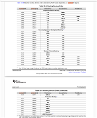
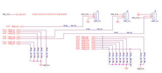
    I want to know the meaning of "a no-boot sysboot mode" . Are you referring to the sysboot[5:0] configration that is NOT appear in this picture below?

    If I guess correctly, please show me your configration of sysboot[5:0].

    My English is poor, but I think you understand what I'm saying.

    Thanks.

    Regards,

    Steve sun

  • Hello Richard,

    I asked this question at segger's forum. Alex thinks you are a very capable guy, and I also highly approve of it.

    https://forum.segger.com/index.php/Thread/9468-Can-not-halt-m4-on-AM572x-evaluation-module-by-JTrace/

    Based on the information provided by both of you, I will try again.

    If you find any new clues, please reply to me.

    Thanks very much.

    Regards,

    Steve sun

  • Hello Steve,

    I was out of the office last week.  Sorry for the delay.  As I mentioned the most likely case is some code execution which is conflicting with your script.  For boot modes, I would suggest picking one which cannot boot (both primary and backup are impossible as your board does not have them).   I usually picked an SD card boot type and just removed the card to get to a known no boot state.  I would guess you might have a QSPI backup which has code running and causing some issue.

    Regards,
    Richard W.
  • Hello Richard,

    I've been dealing with other things these days.

    My board is https://www.ti.com/tool/TMDSEVM572X. Since I bought it from TI, I haven't made any modifications.

    The sysboot[5:0] could be 0bXX 001X. If I don't modify the configuration of the resistors, what can I do to let it get to no boot state.

    I think Alex is right. The A15 is master core, so my jtrace can work correctly. But the M4(IPU) is slave core, how to start it without A15 by jtrace?

    Is it related to the initialization of ICEPICK-D? I have a Reference Guide of  ICEPICK-C, but not  ICEPICK-D.

    I tried to understand what your colleague meant, but it was a bit difficult to understand.

    If you have a jtrace, could you make a jlink script to debug M4?

    Thanks very much.

    Regards,

    Steve sun

  • Hello Steve,

    I do not have a jtrace to try out what is being proposed. It is true that configuration of the M4 can be done using the AHP-AP post an attach to the icepick.  This can be done without touching the ARM core's debug logic.  Since you can connect to the A15 you will have the option to try and control the M4's power/reset/clock using the A15 or the AHP-AP.

    As I was guessing, the primary reason you would not be able to attach to the M4 was if was somehow crashed in a bad state from some previous code execution. You should make sure nothing has run before you try and attach. This might mean corrupting flash code to ensure a failed boot. Regarding the PRCM and the IPU reset status, you should be able to read the reset state from the status registers. Already the IPU gels are manipulating these registers.  I would recommend reading back status and seeing if the IPU is stuck in transition or something else.

    You might also try using CCS or Lauterbach as a way to factor out if there is some tool setup issue vs. a board state issue.

    Regards,
    Richard W.
  • Hello Richard,

    Thanks very much.

    I will follow your train of thought and try again.

    Regards,

    Steve sun