This thread has been locked.

If you have a related question, please click the "Ask a related question" button in the top right corner. The newly created question will be automatically linked to this question.

AM6442: Example for Internal ADC from PRU?

Part Number: AM6442

Tool/software:

Hi there!

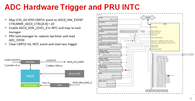
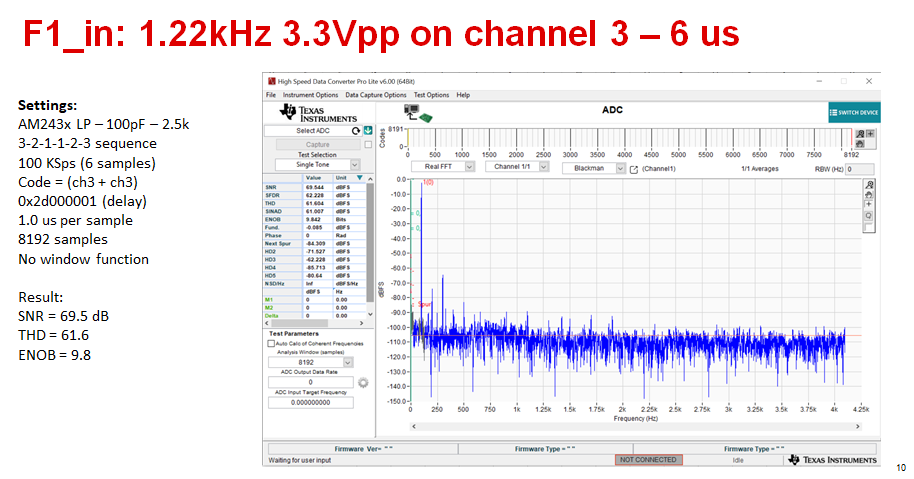
Is there an example to access the internal ADC from the PRU?

Regards.

PS: We can read from the R5F in a high priority thread, but we would have to get PPS and sync clocks with the PRU and since we solved this already for PRU with your help, we're considering the first alternative. That is, sampling with the same PRU_ICSSG.

  • Hello Nelson,

    Yes and no.

    So from a "PRU controlling the internal ADC" standpoint, the code should be similar to the existing AM335x example:
    https://git.ti.com/cgit/pru-software-support-package/pru-software-support-package/tree/examples/am335x/PRU_ADC_onChip

    However, on K3 architecture devices, the cores need to request ownership of peripherals from the device management (DM) firmware before it starts interacting with the peripheral. At this point in time, we do not have an example of how to do this on PRU. It should definitely be possible, I just haven't done it myself yet.

    If you want, I can poke around and ask my other team members if they have sample code. Just let me know!

    Regards,

    Nick

  • Thanks Nick.

    Any examples will be welcome!

    In the end, it would be enough if we can trigger sampling (125kSPS) by using an interrupt from the IEP timer of the PRU, where I have the other ADC. So we don't mind configuring the ADC in R5F and triggering from PRU.

    In case this makes things easier.

    Using/configuring the ADC in the R5F was fast starting from the SDK example so we have this part of the code. We use a single channel.

    Regards.

  • Hello Nelson,

    Sounds good. I'll ask around. I am still catching up from a long vacation, so if I haven't replied by the middle of next week please ping the thread to make sure I don't lose it.

    Regards,

    Nick

  • Hi Nick. Pinging thread. Regards.

  • Hello Nelson,

    Thanks for the ping.

    It sounds like all cores need to request ownership of the peripherals from the Device manager core - except the PRUs. It sounds like the PRUs should work similar to on previous devices, where you just have to make sure the peripheral is not requested by any other processor cores (that means it needs to be explicitly DISABLED in Linux devicetree file), and then the PRUs would be in charge of directly modifying the config registers to enable the clock signal to the peripheral, configure the peripheral, etc.

    Regards,

    Nick

  • Thanks Nick. Checking. Or next goal is to check if we can get the ADC as fast as we can from the R5F.

  • Hello Nelson,

    Sounds good. Apologies that I don't have any sample code to show you for AM64x, but feel free to post with followup questions if you run into any roadblocks.

    Regards,

    Nick

  • Hi Nick. We are checking and so far we think the best approach for timing samples is to capture the IRQ of the ADC in the PRU and then the data can be read in user-space from the FIFO. Does this make sense?

  • Hello Nelson,

    Double-checking on the design

    I am not sure I understand your design. We've been talking about R5F getting data from the ADC (and potentially using R5F to initialize the ADC), but using PRU to sample the ADC (or perhaps initialize the ADC itself), and now we're discussing Linux userspace?

    Which core is the one that will be eventually consuming the ADC data?

    What OS is running on that core?

    How precisely do you need to sample the ADC data?

    If you are waiting on an IRQ instead of manually sampling, why does clock synchronization matter?

    There are a bunch of different ways to do this, so I want to make sure that I don't accidentally point you towards writing unnecessary code or a non-optimized design.

    A note on sampling 

    I assume you'll need to get a sample every 8 usec (125kSPS), which is not something you can rely on Linux to do.

    One potential option is to program the ADC_STEPDELAY register so that the ADC itself is only sampling once per 8 usec, and then whoever is servicing the ADC just needs to empty the FIFO and keep track of which time each measurement should have been taken. It's been a couple years since I did low-level timing math on ADC sampling, so off the top of my head I couldn't tell you exactly what settings to use to get a certain sample rate.

    Another, potentially simpler option is to just manually trigger an ADC sample at the desired time, similar to how we do it in that PRU/ADC example I linked above: https://git.ti.com/cgit/pru-software-support-package/pru-software-support-package/tree/examples/am335x/PRU_ADC_onChip 

    Regards,

    Nick

  • Hi Nick, thanks for your reply.

    > Nick Saulnier said:
    > and now we're discussing Linux userspace?

    Oh yes. Sorry.

    Our goal is to get 1 channel of the internal ADC to userspace (Linux). For now up to 125kSPS, faster would be nice.

    But please read on as this ADC is not the only one in the scenario.

    > Nick Saulnier said:
    > If you are waiting on an IRQ instead of manually sampling, why does clock synchronization matter?

    Scenario:

    - We are already sampling another ADC with PRU1_0. And using an IEP timer. Things working well.
    - We plan to timestamp those samples soon using PTP/PPS. We have PPS working already.
    - We need to match the internal ADC samplings to those of the external ADC (it's OK if it's a known time-offset we can compensate for).

    So, we thought that since we will  timestamp in the PRU, we could use the same IEP registers for the internal ADC samples.

    - We don't mind about the core that initializes the ADC, as long as we can sample fast (125kSPS for now) and with little jitter.
    - We don't mind who gets the data from the FIFOs, could be PRU or R5F.

    PS:

    I noticed that for the PRU example you provided the device is the external address. Does this mean that sampling from the PRU is slower than in the R5F?
    /* Definition of Touchscreen/ADC register structures. */ #define ADC_TSC (*((volatile sysTscAdcSs*)0x44E0D000))

  • Hello Nelson,

    Ahh, got it. So to confirm the usecase:

    PRU1_0 is sampling an external ADC (through this method, or some other way: https://software-dl.ti.com/mcu-plus-sdk/esd/AM64X/09_02_00_50/exports/docs/api_guide_am64x/DRIVERS_PRU_ADC.html ), and then we also want to sample 1 channel of the internal ADC for Linux (where the other channels on the internal ADC are unused).

    What is the allowable error in sample time for the two ADC instances? (e.g., do the samples need to be within 1 msec of each other? 1 usec? etc)

    Suggestions 

    The easiest way to match the ADC samples from the external ADC & the internal ADC is probably by using the same core (or at least the same PRU subsystem) to manually sample both ADCs (as opposed to programming ADC_STEPDELAY to sample at a set data rate, where the ADC clock may not be aligned with the PRU clock or the Linux system time that the PRU is keeping track of).

    In that design setup, the only variation in sample time would be due to differences in the time it took the PRU signal to request the sample to go from the PRU to the internal/external ADC, the amount of time it took for the ADC to capture a sample, and the amount of time it took for that ADC value to make it back to the PRU core.

    PRU is going to be the most deterministic core you have available to you (i.e., lowest jitter), as you can know exactly what it is doing every clock cycle by directly programming the code in assembly (either just the time critical parts of the code, or the entire program).

    ADC address? 

    I am not sure I understand the question. Could you restate it for me?

    Either R5F or PRU cores will need to use the system address & system busses for ADC access, since (as far as I am aware) there is not a separate, direct trace between either subsystem and the ADC that could be accessed by reading or writing to a different address.

    Regards,

    Nick

  • > PRU1_0 is sampling an external ADC

    Yes, we bitbang and can sample fast (1us).

    > What is the allowable error in sample time for the two ADC instances? (e.g., do the samples need to be within 1 msec of each other? 1 usec? etc)

    As long as we know the offset (as much as we can know it) we can delay channels to make them match. Or maybe discard some samples. We're in the order of 8 usecs now but planning to move to 1us soon.

    So, it really depend on what we can do.

    We would use the PRU1_1 for the internal ADC.

    > I am not sure I understand the question. Could you restate it for me?

    Yes, it was about direct access. Last year you told me that querying the global clock was very slow and you just confirmed there is no direct access for the internal ADC.  So wondering if it is the same case with the ADC. Perhaps we need to work with IRQs. Tips appreciated and thank-you for the help so far.

  • Hello Nelson,

    Ok, if you're dealing with sample offsets on the order of usec, I would probably be most comfortable designing the system so that the same PRU subsystem sampled both ADCs.

    There might be some uncertainty for PRU accesses to the internal ADC if it has to share the same bus as other potential traffic, I'm not sure off the top of my head. You could use the PRU cycle timer to benchmark read times for both the internal ADC and the external ADC to get a feel for total time envelope to complete each measurement (i.e., fastest & shortest reasonable times).

    "slow" is a relative term - access to the GTC is definitely "slow" relative to accessing the IEP timer if you're trying to get a timestamp, but depending on someone's usecase that access latency might be permissable for their design.

    When it comes to accessing the internal ADC, I would not expect PRU accesses to take significantly longer or shorter than Linux or R5F accesses (from the standpoint of "electrons moving through the processor, and actually performing the read or write"). In fact (without running benchmarks) I would expect the PRU to do it faster since it can be so tightly programmed, even though the PRU core is running at a slower core clock frequency.

    Regards,

    Nick

  • Nick, Nelson,

      I have done PRU based trigger and PRU read out of on-chip SAR for pseudo simultaneous sampling. Below is the scheme

    Basically defined two tasks on PRU.

    - tm_ADC_trigger - called with cmp15 it for cyclic sampling, re-arm cmp15 for next cycle

    - tm_ADC_capture - called with ADC_GEN_LEVEL_0 event to read FIFO and re-arm capture sequence for next round

       .include "include/icss_regs.inc"
    
    ;CCS/makefile specific settings
        .retain     ; Required for building .out with assembly file
        .retainrefs ; Required for building .out with assembly file
    
       	.global     tm_ADC_capture
       	.global     tm_ADC_trigger
    
    ; ----------------------------------------------------------------------------
    ; task tm_ADC_trigger is called with cmp15 hit event and writes
    ; time stamp of iep timer and isr counter to ICSS memory
    ; ----------------------------------------------------------------------------
    
    tm_ADC_capture:
        xout    BANK0_ID, &r0, 27*4     ; save R0-r26
    ; read iep into r27
        lbco   &r26, c26, 0x10, 4
        ldi32  r3, 0x28001000
    ; read fifo word count
        lbbo   &r9, r3, 0xe4, 4
    ; read data from fifo0
        ldi32  r3, 0x28001100
        lbbo   &r10, r3, 0x0 , 24
        sbco   &r9, c24, 0x10, 28
    
    ; process data channel 3 - sum and divde by 2
        add   r10.w0,r11.w0, r14.w0
     ;   lsr   r10.w0,r10.w0, 1
        ldi32 r3,0x00010000
    
        sbbo   &r10, r3, r27.w0, 2
        add    r27.w0,r27.w0, 2
        qbne   skip_buffer_rst, r27.w0, r27.w2
        ldi    r27.w0, 0
        lbco   &r2, c24, 0, 1
        qbbc   skip_buffer_rst, r2, 0
    ; debug halt when set in interface
    ; stop iep timer
        lbco   &r3, c26, 0, 1
        clr    r3.b0, r3.b0, 0
        sbco   &r3.b0, c26, 0, 1
    ; wait for halt bit reset
    wait_trace:
        lbco   &r2, c24, 0, 1
        qbbs   wait_trace, r2, 0
        set    r3.b0, r3.b0, 0
        sbco   &r3.b0, c26, 0, 1
    skip_buffer_rst:
    
    ; write new delay parameter in debug mode (16 cycles)
        lbco    &r2, c24, 4, 4
        ldi32   r3, 0x28001000
        sbbo    &r2, r3, 0x68, 4
        sbbo    &r2, r3, 0x70, 4
        sbbo    &r2, r3, 0x78, 4
        sbbo    &r2, r3, 0x80, 4
        sbbo    &r2, r3, 0x88, 4
        sbbo    &r2, r3, 0x90, 4
    
    ; Set EOI to generate next interrupt
    ; ADCWriteEOI(baseAddr);    2800 1020h = 0
        ldi32  r3, 0x28001020
        ldi    r2.w0, 155*256 + 0
        sbbo   &r2.b0, r3, 0, 1
    
    ; clear status of ADSC interrupts
        ldi    r4.w0, 0x1fe
        ldi32  r3, 0x28001028
        sbbo   &r4.w0, r3, 0, 2
    
    ; re-enable steps
        ldi    r4.w0, 0x007e
        ldi32  r3, 0x28001054
        sbbo   &r4.w0, r3, 0, 2
    
    ; clear INTC event
    ; clear interrupt for event 155
    ;  HW_WR_REG8(0x30020024, 155);
        sbco   &r2.b1, c0, 0x24, 1
    
    ; save iep counter to memory
        sbco   &r26, c24, 0x28, 4
    
        add    r28,r28,1
        sbco   &r28, c24, 0x2c, 4
        xin     TM_YIELD_XID, &R0.b3,1  ; exit task after two instructions/cycles
        nop
        xin    BANK0_ID, &r0, 27*4     ; save R0-r26
    
        halt                            ; should never happen
    
    ; ----------------------------------------------------------------------------
    ; task tm_ADC_trigger is called with cmp15 hit event and writes
    ; time stamp of iep timer and isr counter to ICSS memory
    ; ----------------------------------------------------------------------------
    
    tm_ADC_trigger:
        xout    BANK0_ID, &r0, 27*4     ; save R0-r26
        lbco   &r2, c26, 0x10, 4
        sbco   &r2, c24, 0x30, 4
        add    r29,r29,1
        sbco   &r29, c24, 0x34, 4
    
        xin     TM_YIELD_XID, &R0.b3,1  ; exit task after two instructions/cycles
        nop
        xin    BANK0_ID, &r0, 27*4     ; save R0-r26

    For pseudo random sampling  chan 3-2-1-2-3 sequence I have to set certain delay to avoid channel to channel disturbance with single cap in ADC.

    I measure ENOB of 9.8 bits when using 1 us per sample.

    Not sure it helps in your application but I thought it may be useful information.

  • Thanks Thomas, that will be helpful.

    The good thing: Our current status is that with the example Nick gave us we managed to sample from PRU, we start a oneshot capture and then retrieve it from the FIFO it at a later point. A timer drives the acquisition trigger process for this and another ADC.

    Downside: We depend on the Linux kernel to do the Initialization. We haven't been able to make it from PRU. We check what the registers contain and the Linux driver for clues but not being able to solve this.

    Will review what you just sent and report back!

    Thanks!