This thread has been locked.

If you have a related question, please click the "Ask a related question" button in the top right corner. The newly created question will be automatically linked to this question.

AM62P: the guideline of LPDDR4 simulation

Part Number: AM62P

Tool/software:

Hi experts

        Now we are using the AM62P52 to develop our product, and we have completed the layout.

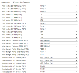
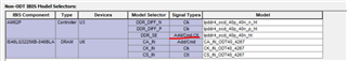
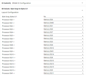
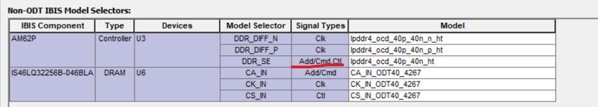
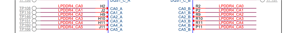
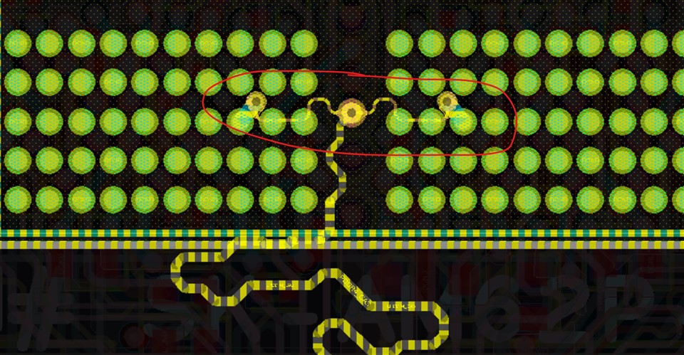
       What is troubling us now is how to adapt the configuration parameters in the AM62Px DDR subsystem to the simulation parameters in Hyperlynx, as shown in the figure below. Is there a simulation guide that can be provided to us? Thank you!

  • Hi JJD

         I have roughly understood how to configure the simulation parameters, but I have two questions that need further answers.

    1、DDR Controller:

                I noticed that the IBIS model has the following configurations for DM and DQ. If I want to use this mode, how should I configure the pull-down to 120 ohm in the AM62Px DDR subsystem?

    lpddr4_ocd_60p_60n_120pd_ht       driver with 60 ohms pd and 60 ohms pu and 120 pd always on, max slew rate

    2、DDR Memory:

               I noticed that the ODT configurations for CA/CSn/CK in the following model recommendations are all 80ohm. I would like to ask whether the ODT values ​​of these three can be configured separately? If so, how to set them in the AM62Px DDR subsystem?

    • Termination: CA ODT (CA/CSn/CKp/n termination): 80ohm

  • 1. At this time, i would not choose that model, instead use lpddr4_ocd_60p_60n.  We have not used the always on pull down 120ohm in any of our testing, so it should not be needed.  

    2.  The ODT values for CA/CSn/CK are set in the memory, and the JEDEC spec does not have provisions to set these separately, they are all set in MR11.

    Regards,

    James

  • Thank you for your support, and I have completed the LPDDR4 simulation, the result is passed.

    but for the AM62Px DDR subsystme, I also have two quesetions:

    1、CSn for the DDR Controller:

           In the simulation software, there is only the Add/Cmd,Ctrl configuration, and no separate Csn configuration, as shown in the figure below. Can I understand that in the AM62Px DDR subsystem, the 80ohm pull-up and pull-down of CSn needs to be configured to 40ohm to keep it consistent with Add, etc.?

    DDR Controller:

    • Driver Pull-Up/Down Lane 0/1 DQ/DM/DQS (DQ/DQS/DM driver): 40ohm
    • Driver Pull-Up/Down CA[5:0] (CA driver): 40ohm
    • Driver Pull-Up/Down CSn (CSn driver): 80ohm
    • Driver Pull-Up/Down CK (CKp/n driver): 40ohm
    • ODT Pull-Down Lane 0/1 DQ/DM/DQS (DQ/DQS/DM termination): 48ohm

    2、Bit Swizzle 0/1/2/3

         I have done the same configuration as EVM, my question is this change has already been implemented in the k3-am62Px-ddr-config.dtsi and does not need to be modified elsewhere?

  • Hello JJD

          Is there any update for my questions?

  • Hi Yong,

    1. The controller has separate driver control for CS and CA.  As was done in the AM62Px configuration, i think you should keep CA 40ohm driver, CS 80ohm driver.  And then in the memory, you can choose 80ohm termination.  With the split CA bus, this would be the best way to match impedances.  What is the trace impedance on your board?

    2. If you have performed the same swizzling/swapping as on the AM62Px SK EVM, then you don't need to change anything in the swizzling section of the configuration

    Regards,

    James

  • Hi JJD

            We designed the layout according to the DDR guideline: point to point, single-ended impedance is 40 ohm

             As described in my question, for Hyperlynx software configuration, CA and CS cannot configure the drive strength separately, that is, CA 40ohm driver and CS 80ohm driver cannot be achieved; so my question is, in this case, should I keep the driver of CA and CS consistent so as to match the simulation results?

  • Let me check

    James

  • Sorry for late reply.  I don't think Hyperlynx should be limited in this way.  I have forwarded your question to one of our simulation experts.

    Regards,

    James

  • Hi,

    Closing the thread, as there is no response for long. Feel free to ping back, if you want to continue discussion.

    Regards

    Ashwani

  • Hi JJD

       Is there any update?

  • Hi James, Sreenivasan, 

    Is there feedback from simulation experts, come to a conclusion would help many others as the impedance setting always is a hot topic on DDR design/configuration.

  • Tony, i think this should be asked back to Hyperlynx.  Their software should have the ability to set a separate CA and CS drive strength.

    Regards,

    James

  • Hi James,

    Thanks, discussed with customer:

    #1. There is not separate CA and CS driver strength setting in Hyperlynx, this is the reality, it is a popular simulation tool not just for TI.

    #2. So can only simulate with same 40ohm impedance for CA and CS, and it passed simulation.

    #3. Their prototype boards passed test with 40ohm configuration so far.

    Questions:

    #1. Still need to change CS to 80ohm in DDR configuration?

    #2. Where is the recommended 80ohm comes from? and why need to be 80ohm?

  • Tony, i would say if they can pass simulations with a certain impedance, then they should use that for silicon.  They should still perform memory stress tests across temp to ensure robustness. 

    Since memories only have one setting for CA/CS, we choose 80ohm.  Then since CS is point to point, CS driver is set to 80ohm.  Since CA signals are T-branched, CA driver is set to 40ohm, and because of the T-branch, each branch would then be 80ohm.  This combination provides the best chance for impedance matching.

    Regards,

    James

  • Since CA signals are T-branched, CA driver is set to 40ohm, and because of the T-branch, each branch would then be 80ohm.

    On EVM board, there is only one DDR device, what is the T-branch comes from? inside the DDR package?

  • Hi Tony,

    No, the CA signals are T-branched on the board to both A and B channels on the memory:

    Here is an example of one of the CA signals from the layout

    Regards,

    James