This thread has been locked.

If you have a related question, please click the "Ask a related question" button in the top right corner. The newly created question will be automatically linked to this question.

AM6442: Triggering DMA for PRU IO Data Capture on AM6422

Part Number: AM6442
Other Parts Discussed in Thread: AM6422, SYSCONFIG

Tool/software:

Hi TI Team,

I’m currently evaluating the AM6422 for a project involving the interface of a 2-channel, 14-bit external ADC. Our goal is to capture ADC data on each rising edge of the clock. The main requirement is to read parallel data from 28 GPIOs and send it to main domain within a 50 ns window, as the ADC outputs data at this rate.

To meet these timing constraints, we are using the PRU for ADC data sampling, as it provides the best timing performance on the AM6422. I have measured the GPIO read/write timing using the PRU and can achieve the 50 ns window for reading samples.

I am considering using DMA, triggered by the clock’s rising edge, to read the PRU IO data and transfer it to the main domain. Is it possible to configure DMA in this way and read data directly from the PRU IO? I’ve reviewed the ADC example (api_guide_am64x/DRIVERS_PRU_ADC.html), but haven’t found any references to using DMA triggered by the GPIO interrupt or clock's edge.

Could you please direct me to any relevant documentation or examples that could assist with this?

Thanks in advance for your support.

Best regards,
Shivangi

  • Hi Shivangi,

    Thanks for your query.

    The assigned expert is out of office. Responses to this thread will be delayed. 

    Thanks for your patience.

    Regards,

    Tushar

  • Hi Shivangi,

    You try below methods to achieve your requirement .

    Method 1 :  Read GPIO pins with out PRU core on MAIN domain .

    Connect all ADC GPIO pins in sequence banks for SOC  .

    Like there are two banks each bank supports for 16 pins and we need mostly two banks 32pins to read 24 pins .

    Configure to trigger DMA based on the GPIO rising edge this pin .

    The below FAQ is explains how to trigger DMA based on the GPIO input .

    In your requirement , you need to change the source address must be the GPIO data Registers .

    Here , the DMA interrupt is triggered reaching to x bytes ..This x mostly greater than 64 bytes .

    https://e2e.ti.com/support/processors-group/processors/f/processors-forum/1378150/faq-how-to-trigger-dma-with-the-help-of-gpio-on-am64x-am243-and-am62x-devices#:~:text=And%2C%20to%20trigger%20DMA%20from,%E2%86%92%20IA%20%E2%86%92%20Destination%20core

    Method 2 :  Read GPIO pins with PRU core 

    As you mentioned above the PRU is handling to read all ADC pins . Then copy this data to PRU memory.

    So, now you need to read this data in the main domain.

    After reading data completion, you just change any dummy pin from low to high or high to low, then this pin activates the DMA to transfer data from PRU memory to Destination Memory .

    or after reading data in PRU memory use the IPC method to share data from PRU core to Main Domain memory..

    Regards,

    Anil.

  • Hi Swargam,
    I have some questions about setting up a GPIO interrupt, based on the provided FAQ: 

    e2e.ti.com/.../faq-how-to-trigger-dma-with-the-help-of-gpio-on-am64x-am243-and-am62x-devices


    - Following the suggestions, I changed the source address from PSRAM to PRU_ICSSG0_RAM_SLV_RAM (0x030010000) to fit my requirements and ran the program. 
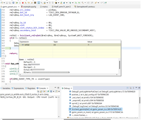
    - However, the code seems to get stuck at Sciclient_gpioIrqSet(). Any insights into why this might be happening?
    - Additionally, I need to switch the GPIO trigger pin to PRG1_PRU1_GPO18 for my setup. Could you advise which GPIO_MUX Router to select and how to configure it? I reviewed the FAQ, but I found the steps a bit confusing.
    - Do I also need to make modifications in the sciclient_defaultBoardcfg_rm.c file? I was able to access the resource management configuration in the sysconfig window, but I’m not clear on what settings should be adjusted.


    Any help would be much appreciated!

    Thanks,

    Vraj

  • Hello Vraj,

    Actually, here is the SCI client problem with the resource allocations.

    Actually, if you look at the above FAQ, I routed GPIO Router 16 output to all destination cores in the sciclient_defaultBoardcfg_rm.c file.

    This change is missing in your environment and this needs to be integrated into your application and later compile the sciclient_defaultBoardcfg_rm.c file and compile the SBL and load the SBL.

    All these steps are properly given information in the FAQ and links you need to go through them and follow the same steps.

    Regards,

    Anil.

  • Hi Anil,

    I routed GPIO Router 16 output to all destination cores in the sciclient_defaultBoardcfg_rm.c file

    Have you tried this thing manually? because when I tried to change the file manually and recompiled the code, then the manual changes were gone.

    This file was auto-generated by SysConfig.
    Can you suggest what I may be missing in SysConfig configurations, due to which I am not able to see the changes as yours?

    Thanks,

    Vraj

  • Hello Vraj,

    Yes, unfortunately, the above config is not supported in syscfg and I will raise the bug.

    To manually compile, you can follow the steps below.

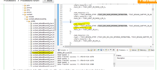
    Add the router configure below to sciclient_defaultBoardcfg_rm.C file 

            {
                .num_resource = 1,
                .type = TISCI_RESASG_UTYPE (TISCI_DEV_MAIN_GPIOMUX_INTROUTER0, TISCI_RESASG_SUBTYPE_IR_OUTPUT),
                .start_resource = 16,
                .host_id = TISCI_HOST_ID_ALL,
            },

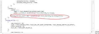
    Next, increase the size of the new entry point to 182, and previously it was 181 and now added one entry.

    So, it increased to 182 .The entry size number may vary or not vary based on the MCU+SDK version.

    In my test set up, I have used versions of the MCU+SDK 10 version and, in that, the value is 181 and after adding one entry it is 182.

    Next, to complete these files, give commands below.

     gmake -s -C .\tools\sysfw\boardcfg  SOC=am64x

    After that you can follow steps from the above FAQ.

    Regards,

    Anil.

  • Hi Anil,

    I have implemented the changes you suggested and successfully compiled the sciclient_defaultBoardcfg_rm.C file.

    My EVM kit is set to NoBoot mode.

    Additionally, I recompiled the SBL, from SBL Null example, loaded the JS file as per the provided steps, and also recompiled the sciclient_ccs_init example.

    However, when I run the program, I encounter an error with the Sciclient_rmIrqSet() API, which returns a value of -1. Following this, the message [Error] Sciclient event config failed!!! is printed.


    Could you please assist me in resolving this issue?

    Thanks,

    Vraj

  • Hello Vraj,

    I am looking at your queries and you may expect reply by today .

    Regards,

    Ani

  • Hello Vraj,

    My EVM kit is set to NoBoot mode.

    Additionally, I recompiled the SBL, from SBL Null example, loaded the JS file as per the provided steps, and also recompiled the sciclient_ccs_init example

    It seems that you are not looked at the FAQ. I clearly explained all steps.

    After completing the SBL, then you need to flash the updated SBL 

    You can follow the steps below now.

    Use the SBL_NULL cfg file and flash the updated SBL bin file. 

    https://software-dl.ti.com/mcu-plus-sdk/esd/AM64X/10_00_00_20/exports/docs/api_guide_am64x/GETTING_STARTED_FLASH.html

    SBL null initializes all the cores, then users direct connects debugger to all cores  rather than every time loading java scripts.

    Next after flashing the SBL , put the EVM in ospi boot mode rather than no boot mode. connect debugger to R5F core , load example .

    Regards,

    Anil.

  • Hi Anil,

    As per your suggestion, I followed the provided link and initially flashed the hello_world example to understand the behavior of flashing an application in OSPI mode.

    Subsequently, I flashed the UDMA project mentioned in the FAQ,

    AM6442: Triggering DMA for PRU IO Data Capture on AM6422.

    But it did not produce any output. To investigate further, I imported the gpmc_psram_io example project from the SDK and made changes similar to those specified in the FAQ example for UDMA. However, when I flashed this modified project in OSPI mode, I encountered the error:

    [Error] Sciclient event config failed!!!

    I then reviewed my sciclient_defaultBoardcfg_rm.c file and found that it already contained the changes mentioned in the FAQ.

    To ensure accuracy, I recompiled the sciclient_defaultBoardcfg_rm.c, rebuilt the sbl_null, and flashed it again.

    After completing this setup, I reflashed the updated project but continued to encounter the same error:

    [Error] Sciclient event config failed!!!

    In conclusion, I am able to flash my project successfully in both No Boot Mode and OSPI Boot Mode, but the error persists. I kindly request your assistance in resolving the issue of Sciclient config failure.

    Thanks & Regards,
    Vraj Joshi

  • Hello Vraj Joshi,

    I assume that you seem to be not following the steps properly.

    You are compiling sbl null and flashing sbl null and then flashing the application from OPSI. These steps are not correct.

    After building the SBL null, then flash only the SBL null image with the updated bin file.

    Later, directly load an application from CCS.

    If you want to use SBL_OSPI rather than SBL null, then compile the SBL OSPI and flash the hello world example and not  your DMA application.

    If you flash your DMA application from OSPI, loading the same application from CCS, you will get the SCI client error.

    Since when you flash your DMA application from OSPI , SYSFW is allocated the resources (GPIO router ) for your DMA application core and

    while loading the same application from CCS , then SYSFW will not allocate the same resources for twice hence you will get an SCI error.

    If you still face a problem, then I can give SBL OSPI image file. You can use my file and flash it on your HW and load the example from CCS and 

    see if you still getting SCI client errors or not.

    Regards,

    Anil.

  • Hi Anil,

    Thank you so much being so patient and helpful.

    I’m happy to share that I finally managed to run my DMA example after resolving the error.

    While I had completed most of the steps correctly, the issue was caused by not updating the path for the compiled SBL file in the config file which we are running in UART mode.

    I have one final query. I’m running my EVM in OSPI mode with a compiled SBL NULL. On powering up the EVM, I see the following logs:

    Starting NULL Bootloader ...

    DMSC Firmware Version 10.0.8--v10.00.08 (Fiery Fox)
    DMSC Firmware revision 0xa
    DMSC ABI revision 4.0

    INFO: Bootloader_runCpu:180: CPU r5f1-0 is initialized to 800000000 Hz !!!
    INFO: Bootloader_runCpu:180: CPU r5f1-1 is initialized to 800000000 Hz !!!
    INFO: Bootloader_runCpu:180: CPU m4f0-0 is initialized to 400000000 Hz !!!
    INFO: Bootloader_runCpu:180: CPU a530-0 is initialized to 800000000 Hz !!!
    INFO: Bootloader_runCpu:180: CPU a530-1 is initialized to 800000000 Hz !!!
    INFO: Bootloader_loadSelfCpu:232: CPU r5f0-0 is initialized to 800000000 Hz !!!
    INFO: Bootloader_loadSelfCpu:232: CPU r5f0-1 is initialized to 800000000 Hz !!!
    INFO: Bootloader_runSelfCpu:242: All done, reseting self ...

    After this, I load my application via CCS, and it runs without any errors. However, during development, I often modify and reload the application without rebooting the board. In this case, I encounter a SciClient config failure. If I reboot the EVM and then load the application, it works fine on the first attempt.

    I think this is the case which you mentioned in previous answer that SYSFW will not allocate the resources twice. Could you confirm if my understanding is correct? Additionally, is there any way to avoid rebooting the board each time?

    Thanks,

    Vraj Joshi

  • After this, I load my application via CCS, and it runs without any errors. However, during development, I often modify and reload the application without rebooting the board. In this case, I encounter a SciClient config failure.

    Hello Vraj Joshi,

    Good to hear that you have solved the issue.

    The DMSC core is creating  an issue.

    As I mentioned above, the GPIO Router 16 output is allocated by the DMSC core when you call SCI call from your application for the first time.

    And, next time you modified  the code and not reset the SOC, then load an application from CCS, then you will get an issue.

    Here, the DSMC core is already allocated GPIO Router 16 to R5F core.

    Again you are trying to call the SCI API to allocate GPIO Router 16 for the second time and this is not possible. Since, DMSC core can allocate Resources for one time if user again sends same request then DMSC core can't allocate Resources and it gives negative response .

    To avoid these SCI client errors, you have to reset (WarmReset from CCS or POR ) the SOC for every loading application from CCS .

    For every loading an application , you do Reset from CCS with the step below and load an application .

    If you flash DMA application from OSPI, then you can't load the same application from CCS again. You may get an SCI client error.

    For development, use the SBL Null and load the Application from CCS and after modifying your code and before loading an application, do reset the SOC either from CCS or POR.

    I am closing this thread and you can open new threads for new queries.

    Regards,

    Anil.

  • Thanks Anil, 
    Resetting the System (mentioned in the image) has worked for me. Now I won't need to reboot the evm kit everytime. 

    For future reference, here are the steps I followed to get the example working:

    1. Followed the instructions in this FAQ: (e2e.ti.com/.../faq-how-to-trigger-dma-with-the-help-of-gpio-on-am64x-am243-and-am62x-devices)

    2. The FAQ mentioned modifying the sciclient_defaultBoardcfg_rm.c file. I referred to the steps provided in this guide: (https://software-dl.ti.com/mcu-plus-sdk/esd/AM64X/latest/exports/docs/api_guide_am64x/RESOURCE_ALLOCATION_GUIDE.html). Since these changes weren’t supported by SysConfig, I manually updated the file and compiled it following the steps in the guide.

    3. Downloaded the example mentioned in the first FAQ, but it didn’t work as expected. Instead, I imported the gpmc_psram_io example from the SDK and applied the UDMA-specific modifications described in the FAQ.

    4. Then, I referred to this FAQ: (https://software-dl.ti.com/mcu-plus-sdk/esd/AM64X/10_00_00_20/exports/docs/api_guide_am64x/GETTING_STARTED_FLASH.htmlfor instructions on compiling and loading the SBL.

    5. My mistake was overlooking the need to update the path for the compiled SBL file in the configuration. While I updated the paths for the application image files, I missed updating the path for the new SBL file, which was generated in the workspace directory.

    Once I corrected this, the application worked perfectly.

    Regards,

    Vraj