Tool/software:
I have a breakout board that I’m using in between the BBB and its DDR3L chip. I’ve verified that the memory chip functions properly without the breakout board, but once the board is attached, I get some really weird behavior on the memory traces during memory initialization.
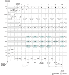
So here’s how the RAM init process should start.

But check this out: We can see #1 from the above process, where CE (blue) goes low. After 700 ms or so, the CK (yellow) starts running. No idea why, but CE is still low during that time. But see that jitter on the CE line right as the CK starts? Yet It’s only right after the CK stops that CE goes high again…

I considered that this jittering could come from cross-talk on the interposer… I’m having a hard time getting the cross-talk “calculator” in AD to behave. But an online calculator says that the cross-talk between the CK and CE lines due to the breakout board should be negligent, on the order of 2 or 3 mV… And that jitter seems to be more than that. Perhaps this could be a by-product of cross-talk and supply-voltage fluctuations in the ASIC itself, which TI deemed an acceptable amount. But we don’t know that.
However, there is a part of me that wonders if perhaps the SoC has trouble driving both the CK and CE lines together without termination resistors - because while they do help with SI, they also should help with drive. I didn’t think drive-strength variations were possible in DDR3, but what about a drive issues overall?
Weirdly enough, after the CK stops and the CE goes high again, the SoC procedes to communicate with the RAM like the RAM’s actually listening or something…
See here the CK (yellow) and the DMU (blue).

And here the CK (yellow) and an ADDR trace (blue).

CE stays high during all of this, but CK doens’t run, although you can see it jitter a bit in the sections where the second sampled trace (blue) gets pulled up and down.
Interestingly enough - you know how sometimes during a failed boot process, the LEDs sometimes count up and down, even minutes after initially powering the board on? When those LEDs change like that, the SoC memory controller seems to want to try doing something, presumably re-initializing. See the CK (yellow) and DMU (blue).

I’m trying to figure out what’s going on. Why does CE stay pulled low when CK is pulled high? It’s like the SoC thinks the CK and CE are both functioning properly, then gets weird when it can’t finish init?
The primary purpose of the termination resistors is prevent reflections and ringing. They’re not really supposed to do that much in terms of drive, but at the same time, the SoC n’t wasn’t designed to be the absolute best possible chip ever. It was designed to be cheap. TI has a document detailing errors they made in the silicon itself, so I’ll check into that today and see if there’s anything noteworthy there. The trm notes that one particular memory function has to be implemented in software because of a silicon error, but iirc, it was rather obscure and didn’t seem to pertain to what we were doing… 
Does anyone have any thoughts or suggestions about this?