This thread has been locked.

If you have a related question, please click the "Ask a related question" button in the top right corner. The newly created question will be automatically linked to this question.

AM62A3: NorFlash S28HS512T sector erase failed

Part Number: AM62A3
Other Parts Discussed in Thread: SYSCONFIG, UNIFLASH

Tool/software:

hi  TI experts

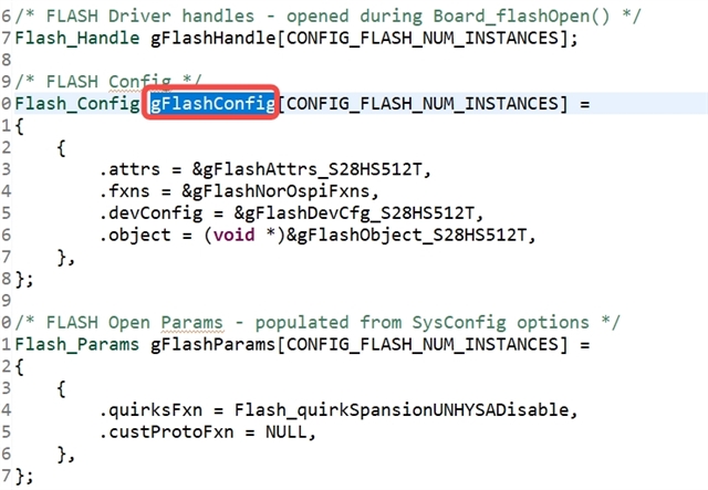
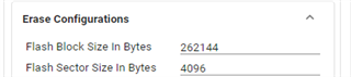
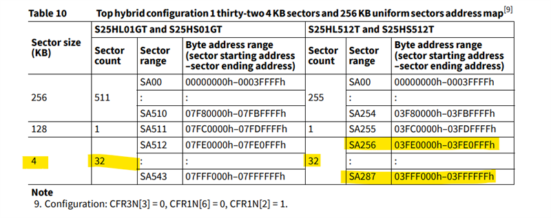
         Now we use norflash  memory S28HS512T  which is  accessed  through  AM62A3 OSPI  interface  in our  customized board,   if  using   " int32_t Flash_eraseBlk(Flash_Handle handle, uint32_t blockNum) "   function( erase 256k)  , the  used  flash block can be erased  successfully and  user data can be wrote to Nor flash device correctly;

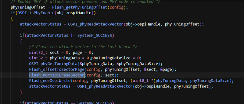
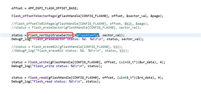
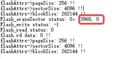
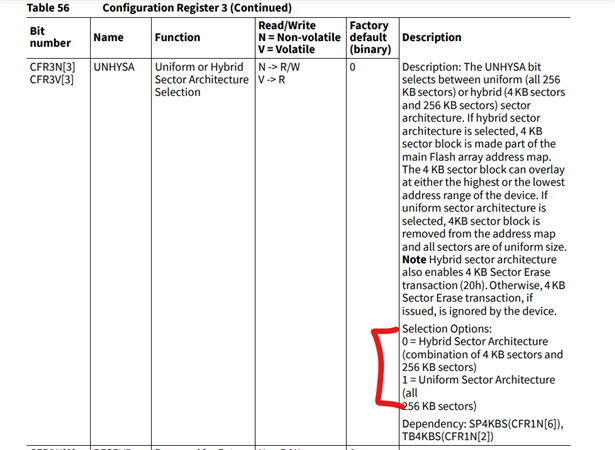
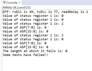
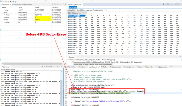
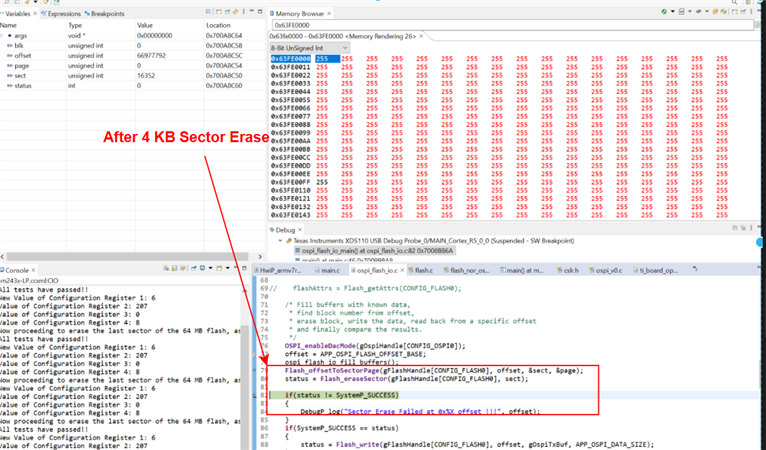
           but if  use  "int32_t Flash_eraseSector(Flash_Handle handle, uint32_t sectorNum) (erase 4K)"   function,  the erase and  write operation  will be failed.

           in fact,  most time we may just  modify  a few bytes data  in one sector;  before erasing flash,  we can copy one sector data into global buffer ,  then modify  some bytes data according to the  data

 position offset in the buffer , finally  write data stored  in buffer to the specified sector area,  there is  no necessary to erase  block area every time ;

        so why  call  the   "Flash_eraseSector()"  function   can`t   erase data  as expected;


  • Hello,

    Allow me sometime to check the implementation of erase sector.

    Regards,

    Vaibhav

  • Hello,

    I would request you to loom through the file: flash_nor_ospi.c

    Please see how Flash_norOspiEraseSector is used.

    Please refer the latest AM62A MCU PLUS SDK.
    FYI, I am pointing you to look through this:

    Let me know if this helps.

    Regards,

    Vaibhav

  • hi  Kumar

          The  MCU SDK is  installed in windows  operation system  and its version is  V9.2 ;

          i  aslo try to install  the latest  version  10.0.0.14 of  MCU SDK ;

         but i can`t  find the function  Flash_norOspiEraseSector(...) as you mentioned  above;

        i  can only find   " int32_t Flash_eraseBlk(Flash_Handle handle, uint32_t blockNum)"  and  "int32_t Flash_eraseSector(Flash_Handle            handle, uint32_t sectorNum)"

  • Hello Ming,

    Please look through the file flash_nor_ospi.c in latest SDK, to search for the API named as Flash_norOspiEraseSector()

    Regards,

    Vaibhav

  • hi  Kumar

             i  have replace flash erase   function  with  "Flash_norOspiEraseSector()"  in my project, but the  erase and write  operation is also  failed.

            as the screenshot show  below , the  "gFlashConfig"  parameter is generated by syscfg file in CCS IDE;

  • Hell Ming,

    Can you please tell me about the values that is offset, sector_val and page in your case?

    I can try this on the AM64x TI EVM as it has the NOR flash part which you are using along with AM62A.

    Regards,

    Vaibhav

  • hi  Kumar

               The flash offset is  0xf80000 ,  sector id  is 3968, page id is 0;

  • Hello Ming,

    Based on the above information, you want to just erase 4096 bytes and not a whole block right?

    Regards,

    Vaibhav

  • hi  Kumar

        we  hope   the  best  option  is  that  block erase  and  sector  erase command can both be  useful,  in  most  time ,  maybe  the sector erase  command can meet our  requirement,

    but  in  software  upgrade    scenario, the  block  erase  can be  more effective

  • Hi Vaibhav,

    Cusrtomer want to use both 4K erase, and block erase based on the SW usercase, so pls help support. Thanks for support.

    BR,

    Biao

  • Hello Ming and Bioa,

    Thank you very much for the clarification I needed.

    So as a part of next steps from my end:

    1. I am going to try erasing a block and see if the operation is successful.

    2. I am going to try erasing a sector and see if the operation is successful.

    In either of the cases, if it fails, then I will debug on my TI EVM setup as to where the failure happens.

    You can expect responses from my end in sometime.

    Thanks,

    Vaibhav

  • Hello Ming,

    Can you calculate which offset will sector number 3968 fall into? This way I can see in the memory browser if the erase operation is happening properly or not.

    Is this offset F80000 = 3968 * 4096?

    FYI, erase block works just fine.

    Regards,

    Vaibhav

  • Hello Ming,

    I have tested this on my end and it turns out that the Flash_eraseSector is broken and does not erase the required sector.

    The workaround is to continue using block erase as of now and as a next action step I have raised a JIRA for this.

    A JIRA has been created for erasing sector failure, as it is not successful.

    I will update here on this thread, once a fix has been proposed.

    Thanks for your patience.

    Regards,

    Vaibhav

  • hi  Kumar

       is  there  any  method  to fix the  sector erase issue.

  • Hi Ming,

    I have asked for an update from the software team on this, currently there has been no updates to the JIRA ticket soo far.

    Once I hear back from them I will get back to you.

    Regards,

    Vaibhav

  • At present, when we use the write function of flash, we can only use the 256k erase interface , and the erase time is about 2s, which will cause all tasks of MCU to be stuck, but the program will continue to run after the flash operation is completed.

    I hope you can come up with a solution。We are in a hurry.

  • Hi Vaibhav,

    any update? customer are pushing for this. pls help priority this.

    BR,

    Biao

  • Hi Biao, Ming,

    Meanwhile I get latest updates from the dev team(they are busy with the release activity), I would like you to go through: https://github.com/TexasInstruments/mcupsdk-core/commit/55af55fd09a#diff-682d5d5c94769777bf011fd29f77e33384dd6db6ef80db885d92645f10825248

    Regards,

    Vaibhav

  • HI ,:


    The MCU version we used is mcu_plus_sdk_am62ax_09_02_00_38, and the file marked above cannot be found.

    You can provide a modification of MCU corresponding to our version

  • Hi Zhaoneng,

    Thanks for your patience.

    I have looked into this and found about this description from the SysConfig Flash tab/section.

    So inside the API named as Flash_quirkSpansionUNHYSADisable the hybrid sector is disabled. You can go ahead and see if this API is called as a part of your execution?

    Regards,

    Vaibhav

  • Hi Vaibhav,

           the   Flash_quirkSpansionUNHYSADisable()  method  is called  in our program. if we  try to  program the S28HS512T to hybrid Top mode(4k sector area located in highest address )   in  our factory product line( S28HS512 CFG1 register bit2  : 1,  CFG3 register bit 3: 0 ;  refer to user manual),  but after the  S28H512T  integrated to our customized circuit board  and power on , the flash IC will be configured  to  uniform mode too( CFG3 register bit3 changed to 1).

        we also try to  modify the Flash_quirkSpansionUNHYSADisable()  method to  prevent  changing the  flash mode to  uniform. but if  we  update the  flash SBL software and download to the circuit board(the CFG3 register bit 3 has been changed to 0 by MCU image before) , the   AM62 can `t  boot up successfully  and the flash can `t be accessed again even if  we  try to power off the machine then power on. SO  we  guess  whether  the  AM62  Rom code  has  changed  the  FLASH register CFG1  register bit2  to  0( if like this , the  flash mode is configured to hybrid Bottom mode, 4k sector area located in the low 128k address, refer to the flash user manual)

     CFG1 register addr : 0x800002(for read)  0x0000002(for write),  CFG3 register addr:  0x800004(for read), 0x0000004(for write)

  • Hi Ming,

    I have read the flash part's datasheet properly and went through the description of the configuration registers 1 and configuration registers 3.

    In Configuration register 3 it is mentioned that, if bit 3 is set to 0, then it acts as hybrid mode.

    This is bit 2 of the configuration register 1:

    This is bit 6 of the configuration register 1:

    Okay so I have read your comments on how you had a particular flash setting out of factory, and once integrated it changes/resets.

    So the reset could be a result of the the API 

    flashFixUpOspiBoot
    being called inside SBL code. Can you please check at what instances throughout the bootloader/application code combined, this API 
    flashFixUpOspiBoot is called?
    Here is the description of the API:
    Regards,
    Vaibhav
  • Hi Vaibhav,

      the  flashFixUpOspiBoot(...)  API  exist in  NOR flash  SBL stage1 and  stage2  project. every time the code boot  up from flash this API will be called.

    we have do  the test,  if  MCU start up normally , then call a test  method to  read  the  FLASH  CFG1  value and  the bit2  printed  is  1( CFG1:  0x04).  as the same as our  factory  product  line configuration. it seems that the flashFixUpOspiBoot(...)  dosen`t  set the nor flash to  Infineon vendor  default value(CFG1: 0X00).

    but   i am not sure why if we  disable the  Flash_quirkSpansionUNHYSADisable(..)  in  SBL project  and  clear  the  CFG3 bit3,  then  the AM62 will  be like  a ' stone' and  can`t  start up anymore.


  • Hi,

    then call a test  method

    Can you send the piece of code which is written inside test API which you have custom written.

    I will try to see the value at my end itself, but would do so on AM62x TI EVM as this EVM has the NOR flash part which the customer has integrated with AM62A.

    Regards,

    Vaibhav

  • Hi Vaibhav,


               The test code and  printed log  show as the screenshot below, it is used to clear  the bit3  of  CFG3 register(0x800004);


            IF we  try to modify the Flash_quirkSpansionUNHYSADisable(...)  like the picture below and rebuild  the  lib of MCU  SDK 9.2  &  flash SBL stage1 project  then download the SBL image , the result is that  our customized board can`t  startup anymore  from  NOR flash .


  • Hi,

    I have gone through your response and read the register values. I have read the datasheet properly.

    So the configuration register 1 has a value of 4, which means here that TB4KBS is 1 and SP4KBS is 0, so it falls under the following category.

    The configuration register 2 has a value of 8, which means that MEMLAT[3:0] is 8. So the Dummy cycles value is 8.

    The configuration register 3 value is 0, which means that UNHYSA is 0, so hybrid sector architecture is enabled(combination of 4kb and 256 kb sectors, but 4kb sectors should be at the top).

    the result is that  our customized board can`t  startup anymore  from  NOR flash .

    So I want to understand the flow here. You already have flashed the images, like bootloader and application images to the flash and then you are trying to boot.

    Or the flashing is not happening to the flash part?

    Also, the logic of applying the hybrid mode is on uart uniflash application, or bootloader application?

    Regards,

    Vaibhav

  • Moreover, I am in constant talks with the development team and trying to find a fix for the same.

    One thing is clear that the drivers are written across all SoCs to operate flash in uniform mode.

    On this note, can you please check with the flash vendor as to what all bits needs to be set in order for us to enable hybrid mode.

    As far as your register values, CFG Registers 1, 2 and 3 are concerned, all looks good to me to enable hybrid mode.

    But it would be nice if you can confirm with the flash vendor so we can be sure that we are not missing out on a bit or two.

    Looking forward to your responses.

    Regards,

    Vaibhav

  • Hi Vaibhav,

           I   have  contact the vendor  FAE to confirm the  Hybrid top mode configuration, they just only  mentioned  the  related  CFG1  , CFG3  register too

          (CFR3N[3] , CFR1N[6] , CFR1N[2] ).

           There is no  other  special  advice  got  from the Vendor  FAE.

  • Hi Ming,

    Thanks for your patience.

    Hi Vaibhav,

           I   have  contact the vendor  FAE to confirm the  Hybrid top mode configuration, they just only  mentioned  the  related  CFG1  , CFG3  register too

          (CFR3N[3] , CFR1N[6] , CFR1N[2] ).

           There is no  other  special  advice  got  from the Vendor  FAE.

    I can understand that the vendor said the following. So the changes are limited to the CFG1 and CFG3 registers as also mentioned here: https://e2e.ti.com/support/processors-group/processors/f/processors-forum/1433720/am62a3-norflash-s28hs512t-sector-erase-failed/5587028#5587028

    I will comment here as soon as I get an update on the JIRA filed for this specific issue. We are actively working on this with the development team.

    Regards,

    Vaibhav

  • Hi Vaibhav,

                  is  there any update message about the NOR flash driver now

  • Hello Ming,

    The subject matter expert is currently out of office for this week. Please expect a delayed response. Thanks for your patience.

    Regards,

    Anil.

  • Hello,

    We are actively working on this query, you can expect responses as soon as we have further updates.

    As a part of next action step, I checked the Status Register 2 value. The register value(bit 2) states about the erase operation being successful or not.

    Currently, for hybrid disabled mode, that is uniform mode, the erase is seen as unsuccessful at offset 0xF80000.

    Regards,
    Vaibhav

  • Hi, 

    Updating as of 17/2/2025.

    Tried to look through various registers for some additional information like status registers 1 and 2 along with ASP(advanced sector protection) registers.

    Currently what I see is a mix of things, so status register 2(bit 2) states 0, which means erase was unsuccessful, but on the other hand status register 1 bit ERSERR(bit 5) is value 0, which means that last erase was successful.

    Will keep you updated on the progress made.

    Thanks,

    Vaibhav

  • Hi Ming,

    I have been able to successfully perform erase operation of 4KB on 4KB Sectors.

    Here is a summary of what I have done to achieve this [PLEASE NOTE: I have achieved this on S25HL512T flash part with 4S-4D-4D mode, but the same thing can be done on S28HS512T with 8D-8D-8D protocol]:

    Firstly, I have changed the mode to Hybrid and made a configuration such that the 4 KB sectors(32 of them) would reside on the top half of the Flash Memory of 64 MB. So they would be residing as shown below:

    To make changes to the configuration registers I have written the code as shown below to the quirks function:

    int32_t Flash_quirkSpansionUNHYSADisable(Flash_Config *config)
    {
        int32_t status = SystemP_SUCCESS;
        uint8_t regData = 0x00;
        uint32_t write = 0;
    
        /* Hybrid Sector Disable */
        status = Flash_norOspiRegRead(config, 0x65, 0x00800004, &regData);
    
        if(status == SystemP_SUCCESS)
        {
            if((regData & ((uint8_t)(1 << 3))) == 0)
            {
                /* Set UNHYSA bit */
                regData |= (1 << 3);
                write = 1U;
            }
            else
            {
                /* No action */
            }
        }
    
        if(write)
        {
            status = Flash_norOspiRegWrite(config, 0x71, 0x04, regData);
        }
    
        // change to hybrid mode, so write the value 0 to 3rd bit UNHYSA on Config Reg 3: 0x800004
        regData = 0x00;
        status = Flash_norOspiRegWrite(config, 0x71, 0x04, regData);
    
        // change config reg1[bit 2] to 1, to make sure 4kb sectors ar at the top, so 32 * 4kb sectors at top.
        regData = 6;
        status = Flash_norOspiRegWrite(config, 0x71, 0x02, regData);    
    
        regData = 0x00;
        status = Flash_norOspiRegRead(config, 0x65, 0x00800002, &regData);
        DebugP_log("New Value of Configuration Register 1: %u \r\n", regData);
    
        regData = 0x00;
        status = Flash_norOspiRegRead(config, 0x65, 0x00800003, &regData);
        DebugP_log("Value of Configuration Register 2: %u \r\n", regData);
    
        regData = 0x00;
        status = Flash_norOspiRegRead(config, 0x65, 0x00800004, &regData);
        DebugP_log("Value of Configuration Register 3: %u \r\n", regData);
    
        regData = 0x00;
        status = Flash_norOspiRegRead(config, 0x65, 0x00800005, &regData);
        DebugP_log("Value of Configuration Register 4: %u \r\n", regData);
    
        return status;
    }

    Once the above piece of change is introduced, the values read from the configuration registers 1, 2, 3 and 4 should be:

    BEFORE:

    At offset 0x3FE0000 I am performing a erase of 4 KB so in the next step the values shown in the memory browser(in the attached screenshot below), would turn to 255(0xFF). 

    AFTER:


    Using a for loop, I have been able to erase all 4 KB sectors(32 of them) successfully.

    I have also been able to erase blocks of size 256 KB(255 of them) which are present from 0x00 until 0x03FBFFFF.


    Regards,

    Vaibhav

  • Hi Vaibhav,


    i have modify the function  int32_t Flash_quirkSpansionUNHYSADisable(Flash_Config *config)  in  file flash_nor_ospi.c, and rebuild the SDK lib(  gmake -s libs PROFILE=release );

    next step  I  rebuild  SBL project and  MCU project and download  SBL image and MCU  image to our  customized Am62 board, the AM62 can not boot from the external FLASH S28HS512 any more after power on,  and we should replace the S28HS512 with a new one in the board to download image again.

  • Hi Ming,

    AM62 can not boot from the external FLASH S28HS512 any more after power on

    This must have happened when earlier you modified flash configuration registers which were non volatile.

    Here is what we can do.

    So, I would like you to perform the following steps:

    1. Replace the flash part with a newer one.
    2. Without any changes in the MCU PLUS SDK code, start fresh and please send me the values of the configuration registers 1,2,3 and 4.

    From this point onwards I can guide you better with the required changes.


    Regards,

    Vaibhav

  • Hi Vaibhav

    the config register value read form the flash like above picture show.

  • Hi Ming,

    Thank you for putting these values forward.

    Allow me sometime to check these values, and suggest you the line of changes required to make sure the flash is arranged in a hybrid mode with the 4KB sectors either on the top or the bottom.

    Regards,
    Vaibhav

  • Hi Ming,

    Please go ahead and operate in 8D-8D-8D mode, and in SysConfig set the clock frequency to 166 MHz, and clock divider to 4.

    Please perform the below operations in order to enable Hybrid sector for Octal Flash: S28HS512T.

    Please replace the API definition as follows:

    int32_t Flash_quirkSpansionUNHYSADisable(Flash_Config *config)
    {
        int32_t status = SystemP_SUCCESS;
    
        // Firstly change to hybrid mode, by setting UNHYSA bit(bit 3) from configuration register 3 to 0. So, regData = 0
        status = Flash_norOspiRegWrite(config, 0x71, 0x04, 0);
        
        // Now change the TB4KBSbit to 1, so in Configuration register 1 set the 2nd bit to 1, regData = 4 written to config reg 1(0x02)
        status = Flash_norOspiRegWrite(config, 0x71, 0x02, 4);
    
    
        uint8_t regData = 0x00;
    
        status |= Flash_norOspiRegRead(config, 0x65, 0x00800002, &regData);
        DebugP_log("Value of Configuration Register 1: %u \r\n", regData);
    
        regData = 0x00;
        status |= Flash_norOspiRegRead(config, 0x65, 0x00800004, &regData);
        DebugP_log("Value of Configuration Register 3: %u \r\n", regData);
    
        return status;
    }

    Once you have done the above change, then your 4 KB sectors will be as follows:

    In the offset, highlighted in the table, you can go ahead and perform a 4 KB erase operation.

    Regards,

    Vaibhav

  • Hi Vaibhav,

        have you  verify this method in your  EVM  board   through  changing  your EVM board to SBL OSPI NOR  flash boot mode .

        if  now your EVM board is not boot in  OSPI NOR  flash boot mode,  you  should try to change  it  to SBL  NOR flash boot( this require there is   S28HS512T located in your  EVM board).

       i  have no more test board in hand now, according to my experience,  using this  configuration,  the S28HS512T in our customized board can also be destroyed  and result in like stone. due to the IC package structure, it is difficult to replace the  S28HS512T with a new one .

  • Hi Ming,

    have you  verify this method in your  EVM  board

    I have verified this at my TI EVM having S28HS512T.

    I have verified at application level when the boot mode set is OSPI NOR Bootmode.

    Please tell me your end to end booting process and what all appimages you are flashing.

    Please correct my assumption:

    1. You se the board to uart bootmode

    2. Then you use uart uniflash to flash one of the config files as shown below:

    3. Post successful flashing, you set the board to OSPI NOR bootmode and boot up.

    Please tell me which config file you are flashing and share a screenshot of the content of the config file.

    Regards,

    Vaibhav

  • Hi Vaibhav,

        i   download the SBL and MCU  image  file  to  S28HS512T  through  SD card, after image file download finished then pull out the SD card and  power on in SBL NOR  FLASH mode.

  • Hi Vaibhav,

        i  want to confirm another thing ,  after you  modify Flash_quirkSpansionUNHYSADisable(...),  do you  rebuild  the SBL stage1 , SBL stage2 project  and download these generated hs_fs  image file   to EVM.

       or you just  download  the new  generated MCU image to EVM,

  •     i  want to confirm another thing ,  after you  modify Flash_quirkSpansionUNHYSADisable(...),  do you  rebuild  the SBL stage1 , SBL stage2 project  and download these generated hs_fs  image file   to EVM.

    I do not rebuild the SBL Stage 1 and Stage 2.

    For me the flow of operation is as follows to check this.

    I simply go ahead and do the following.

    1. Set evm to uart bootmode and then initialize using default sbl null via UART Uniflash.
    2. Post this I se to OSPI NOR bootmode an d I power on the EVM.
    3. I simply connect to the R50_0 core and then I run a sample application OSPI_Flash_IO(modified to erase 4KB sectors) and have this application pick up the logic to use hybrid mode as described above in the steps here: https://e2e.ti.com/support/processors-group/processors/f/processors-forum/1433720/am62a3-norflash-s28hs512t-sector-erase-failed/5687747#5687747

    This is a correct way of testing which I have done.

    Regards,

    Vaibhav

  • SBL stage1 , SBL stage2

    I do not understand why SBL Stage 1 and SBL Stage 2 are required to be rebuilt, as you are going to perform erase operations of 4 KB sector at application level?

    I would suggest let SBL Stage 1 and Stage 2 operate in the usual Uniform mode and then we switch to Hybrid mode as soon as we come to Application.

    Note, I am loading the application via CCS and not flashing it directly on the R5 core.

    My step is to load the ,out file of the application and check for the working of sector erase.

    Please let me know your further thoughts so that we come to a conclusion on this one.

    Looking forward to your response.

  • Hi Vaibhav,

    I would suggest let SBL Stage 1 and Stage 2 operate in the usual Uniform mode and then we switch to Hybrid mode as soon as we come to Application.

    there is a high risk that customer only change the model to Hybrid mode on app level. if app change the mode to hybrid, and somehow board suddenly power off, can't change it back to uninform, this will result next boot load fail. actually, customer already can change NOR mode to hybrid mode at app level, but customer think this is a high-risk operation. so, this is the reason customer ask for sbl change nor flash mode to hybrid one time, and don't change the mode again.

    BR,

    Biao

  • Hi,

    Thanks for the explanation.

    I would like to know the operating clock frequency, clock divider and protocol used in all the files used by Desay SV.

    By all the files I mean, all of them from different Bootloader stage to application.

    Also, ask them to give me the configuration values of all the registers with respect to all the files in use, from bootloader to application.

    They can do so, by simply having the following API changes:

    int32_t Flash_getConfigRegValues(Flash_Config *config)
    {
        int32_t status = SystemP_SUCCESS;
        uint8_t regData = 0x00;
    
        status |= Flash_norOspiRegRead(config, 0x65, 0x00800002, &regData);
        DebugP_log("Value of Configuration Register 1: %u \r\n", regData);
    
        regData = 0x00;
        status |= Flash_norOspiRegRead(config, 0x65, 0x00800003, &regData);
        DebugP_log("Value of Configuration Register 2: %u \r\n", regData);
    
        regData = 0x00;
        status |= Flash_norOspiRegRead(config, 0x65, 0x00800004, &regData);
        DebugP_log("Value of Configuration Register 3: %u \r\n", regData);
    
        regData = 0x00;
        status |= Flash_norOspiRegRead(config, 0x65, 0x00800005, &regData);
        DebugP_log("Value of Configuration Register 4: %u \r\n", regData);
    
        regData = 0x00;
        status |= Flash_norOspiRegRead(config, 0x65, 0x00800006, &regData);
        DebugP_log("Value of Configuration Register 5: %u \r\n", regData);
    
        return status;
    
    }
    
    int32_t Flash_quirkSpansionUNHYSADisable(Flash_Config *config)
    {
        int32_t status = SystemP_SUCCESS;
        uint8_t regData = 0x00;
        uint32_t write = 0;
    
        status = Flash_getConfigRegValues(config);
    
        /* Hybrid Sector Disable */
        status = Flash_norOspiRegRead(config, 0x65, 0x00800004, &regData);
    
        if(status == SystemP_SUCCESS)
        {
            if((regData & ((uint8_t)(1 << 3))) == 0)
            {
                /* Set UNHYSA bit */
                regData |= (1 << 3);
                write = 1U;
            }
            else
            {
                /* No action */
            }
        }
    
        if(write)
        {
            status = Flash_norOspiRegWrite(config, 0x71, 0x04, regData);
        }  
         
        DebugP_log("After Hybrid Sector is Disabled the values are as follows: \r\n");
        status = Flash_getConfigRegValues(config);
    
        return status;
    }

    Regards,

    Vaibhav

  • Hi Vaibhav,

    You mean you need customer apply above api to print the value you need, and then feedback to you, right?

    BR,

    Biao

  • Hi,

    Thanks for your patience.

    Also, ask them to give me the configuration values of all the registers with respect to all the files in use, from bootloader to application.

    They can do so, by simply having the following API changes:

    I am assuming this is done, if so, can I have the values.

    You mean you need customer apply above api to print the value you need, and then feedback to you, right?

    You are correct.

    BR,

    Vaibhav