AM62A7: AM62A7: MCU CAN1 do NOT sent CAN FD with bit rate switching

Part Number: AM62A7
Other Parts Discussed in Thread: SYSCONFIG

Tool/software:

SDK version: 9.2

When we use MCU CAN0, MCU CAN1, and SOC CAN0 in AM62A7, we find that only MCU CAN0 can correctly send and receive FD frame with bit rate switching. When the  MCU CAN1 is configured with the same configuration as MCU CAN0, MCU CAN1 cannot correctly send FD frame with bit rate switching  (standard messages can be sent and received normally).

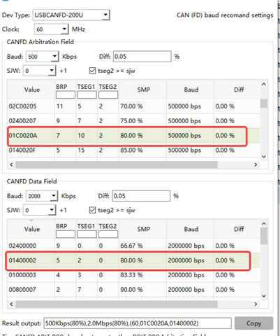
Use ZLG's USBCANFD-200U as a upping debugging device, and set the communication parameters as follows:

Protocol standard: CAN FD ISO, FD frame with bit rate switching function is enable. Arbitration baud rate: 500Kbps, data filed baud rate 2Mbps, and the sample point is  80%.

using this configuration, MCU CAN0 FD frame with bit rate switching can be sent and received normally.

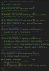
Modify MCU CAN1 communication configuration parameters to be consistent with MCU CAN0. It is found that only standard messages can be sent and received normally, but CAN FD frame with bit rate switching sent by the debugging device can be accepted. When MCU CAN1 try send CAN FD frame with bit rate switching, the interrupt

MCAN_INTR_SRC_PROTOCOL_ERR_DATA is triggered. FD CAN FD frame with bit rate switching sent failed.
Initialized configuration parameters:

/* Initialize MCAN Init params */
MCAN_InitParams initParams;
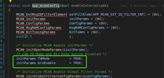
initParams.fdMode = 1; // 0x1U;
initParams.brsEnable = 1; // 0x1U;
initParams.txpEnable = 0x0U;
initParams.efbi = 0x0U;
initParams.pxhddisable = 0x0U;
/* To enable automatic retransmission of the packet,
* program initParams.darEnable to "0" */
initParams.darEnable = 0x0U;
initParams.wkupReqEnable = 0x1U;
initParams.autoWkupEnable = 0x1U;
initParams.emulationEnable = 0x1U;
initParams.emulationFAck = 0x0U;
initParams.clkStopFAck = 0x0U;
initParams.wdcPreload = 0xFFU;
initParams.tdcEnable = 0x1U;
initParams.tdcConfig.tdcf = 0xAU;
initParams.tdcConfig.tdco = 0x6U;
MCAN_init(gMcanBaseAddr, &initParams);
-------------------------------------------
bit rate setting:
/* Configure Bit timings 500Kbps and 2Mbps */
MCAN_BitTimingParams bitTimes;
bitTimes.nomRatePrescalar = 1;
bitTimes.nomTimeSeg1 = 70; // 63;
bitTimes.nomTimeSeg2 = 7; // 14;
bitTimes.nomSynchJumpWidth = 4; // 13;

bitTimes.dataRatePrescalar = 1;
bitTimes.dataTimeSeg1 = 15; // 12;
bitTimes.dataTimeSeg2 = 2; // 5;
bitTimes.dataSynchJumpWidth = 1; // 3;
MCAN_setBitTime(gMcanBaseAddr, &bitTimes);
-----------------------------------------
The above configuration can normally send and receive  CAN FD frame with bit rate switching on MCU CAN0.  but it does not work on MCU CAN1.
the sending code configution is like this:
-----------------------------------------
MCAN_TxBufElement txMsg;
txMsg.id = (uint32_t)((uint32_t)(can_id) << 18U);
txMsg.rtr = 0U;
txMsg.xtd = 0U;
txMsg.esi = 0U;
txMsg.brs = 1U;
txMsg.fdf = 1U;
txMsg.efc = 1U;
txMsg.dlc = size_to_dlc(data_len);
memcpy(txMsg.data, data, data_len % 65);
The above configuration will trigger the MCAN_INTR_SRC_PROTOCOL_ERR_DATA error interrupt when trs is 1 on MCU can1. but on MCU can0 is well.
When the trs is 0 and the fd is 1, the MCU can1 received fd frame normally . but sending fd frame is failed.  but the Standard Classic frame can be sent and received normally.
i try the SOC MCAN0, I meet the same error with MCU CAN1.

Please give me helps.
Thank you.

  • Hi,

    Could you modify the Tseg1 and Tseg2 values in MCAN bit timing parameters and try again. There is limitation on the number of time quantum in each Segment.

    Regards,
    Aparna

  • Hi Aprna, 

    thank you for your helps.

    did you mean modify the data field SP percent? 

    I have try 60% ------------- does't work.   MCAN_INTR_SRC_PROTOCOL_ERR_DATA  interrupt  will be active. -> bus off

    bitTimes.dataRatePrescalar = 1;
    bitTimes.dataTimeSeg1 = 12; // 12;
    bitTimes.dataTimeSeg2 = 5; // 5;
    bitTimes.dataSynchJumpWidth = 1; // 3;

    and 75-------------does't work.   MCAN_INTR_SRC_PROTOCOL_ERR_DATA will be active.  -> bus off

    bitTimes.dataRatePrescalar = 1;
    bitTimes.dataTimeSeg1 = 15; // 12;
    bitTimes.dataTimeSeg2 = 2; // 5;
    bitTimes.dataSynchJumpWidth = 1; // 3;

    and 80% -------------does't work.   MCAN_INTR_SRC_PROTOCOL_ERR_DATA will be active.  -> bus off

    bitTimes.dataRatePrescalar = 1;
    bitTimes.dataTimeSeg1 = 16; // 12;
    bitTimes.dataTimeSeg2 = 1; // 5;
    bitTimes.dataSynchJumpWidth = 1; // 3;
    yes , i try above parameters. the error is still meet.   
    i connect can0 and can1 , used the same bit parameters. 
  • Hi,

    I will check this and get back to you in a few hours.

    Regards,
    Aparna

  • Hi,

    Please check if the internal loopback mode is working properly first.

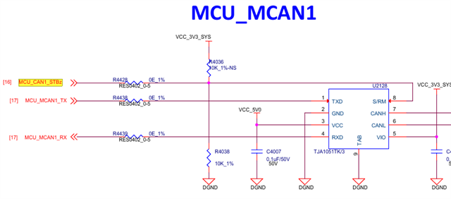
    Next, what are the hardware differences between your MCU_MCAN0 and MCU_MCAN1 connections?

    It is unusual that one CAN instance is working and the other is not, when exactly the same code is used.

    Also, please share the MCAN bit timing parameter settings on your ZLG USBCANFD software.

    Regards,
    Aparna

  • ---Please check if the internal loopback mode is working properly first.

    at the first, the SDK origin code loopback doesn't work.  I will check it again.

     ---- what are the hardware differences between your MCU_MCAN0 and MCU_MCAN1 connections?

    the connections is the same.  i try many times.  

    ------ZLG USBCANFD software.

  • The clock should be 80 MHz

  • yes, am62a's clock si 80MHz,  but ZLG USBCANFD 's clock is 60MHz。 but the bit rate and SP is the same.

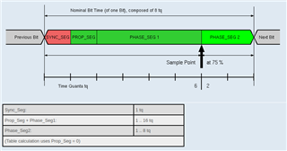
  • Have you referred this document to calculate bit parameters: https://e2e.ti.com/support/processors-group/processors/f/processors-forum/920090/faq-tda4vm-can-how-is-bit-rate-calculated-for-can

    The MCAN_INTR_SRC_PROTOCOL_ERR_DATA interrupt gets triggered when timing parameters donot match.

    Regards,
    Aparna

  • Hi, Aparna

    I check the origin sample on mcu_plus_sdk_am62ax_09_02_00_38/examples/drivers/mcan/mcan_loopback_polling/mcan_loopback_polling.c again,

    it just for MCU_CAN1:

    mcu_plus_sdk_am62ax_09_02_00_38/examples/drivers/mcan/mcan_loopback_interrupt/am62ax-sk/mcu-r5fss0-0_freertos/ti-arm-clang/generated/ti_drivers_config.h
    /* MCAN Instance Macros */
    #define CONFIG_MCAN0_BASE_ADDR (CSL_MCU_MCAN1_MSGMEM_RAM_BASE)
    #define CONFIG_MCAN0_INTR (46U)
    #define CONFIG_MCAN_NUM_INSTANCES (1U)
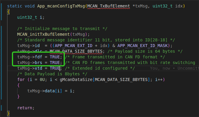
    but it only test the classic can. so I modify the code to support FD and BRS:
    static void App_mcanConfigTxMsg(MCAN_TxBufElement *txMsg, uint32_t idx)
    {
        .......
        MCAN_initTxBufElement(txMsg);
        /* Standard message identifier 11 bit, stored into ID[28-18] */
        txMsg->id  = ((APP_MCAN_EXT_ID + idx) & APP_MCAN_EXT_ID_MASK);
        txMsg->dlc = MCAN_DATA_SIZE_8BYTES; /* Payload size is 64 bytes */
        txMsg->fdf = TRUE; /* Frame transmitted in CAN FD format */
        txMsg->brs = TRUE; /* CAN FD frames transmitted with bit rate switching  */
        txMsg->xtd = TRUE; /* Extended id configured */
        ......
    }
    I have done 3 tests:
    1. Case 1. use the default timing parameters, Normal:1Mbps Data:5Mpbs,can loopback mode is enable.
    MCAN_BitTimingParams gMcanBitTimingDefaultParams =
    {
        .nomRatePrescalar   = 0x7U,
        .nomTimeSeg1        = 0x5U,
        .nomTimeSeg2        = 0x2U,
        .nomSynchJumpWidth  = 0x0U,
        .dataRatePrescalar  = 0x1U,
        .dataTimeSeg1       = 0x3U,
        .dataTimeSeg2       = 0x2U,
        .dataSynchJumpWidth = 0x0U,
    };
    here enableInternalLpbk = true;
     configure timing parameters  to 1Mbps and 5Mbps:
    clock: 80M
    Normal:
    TSEG1= 5 + 1 = 6
    TSEG2= 2 + 1 = 3
    Presalar=7+1=8
    so FLOCK = 80/8= 10MHz

    Tq Nums: (1+TSEG1 + TSEG2) = (1+6+3)=10 , so bitrate: 10M/10 = 1Mbps, and SP: (1+6)/10 = 70%.

    Data:  
    TSEG1= 3 + 1 = 4
    TSEG2= 2 + 1 = 3
    Presalar=1+1=2
    so FLOCK = clock/Presalar  = 80/2 = 40MHz

    Tq Nums: (1+TSEG1 + TSEG2) = (1+4+3)=8 , so bitrate: 40M/8 = 5Mbps, and SP: (1+4)/8 = 62.5%.

    result:All tests have passed!!

    2.  Case 2: use the custom timing parameters, Normal:500Kbps Data:2Mpbs,can loopback mode is enable.
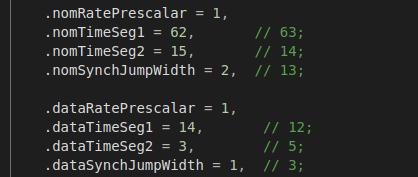
    MCAN_BitTimingParams gMcanBitTimingDefaultParams =
    {
        .nomRatePrescalar = 1,
        .nomTimeSeg1 = 62,      
        .nomTimeSeg2 = 15,      
        .nomSynchJumpWidth = 4,  
    
        .dataRatePrescalar = 1,
        .dataTimeSeg1 = 14,      
        .dataTimeSeg2 = 3,       
        .dataSynchJumpWidth = 1, 
    };
    clock: 80M
    Normal:
    TSEG1= 62 + 1 = 63
    TSEG2= 15 + 1 = 16
    Presalar=1+1=2
    so FLOCK = clock/Presalar = 80/2 = 40MHz

    Tq Nums: (1+TSEG1 + TSEG2)=(1+63+ 16) = 80 , so bitrate: 40M/80 = 500Kbps, and SP: (1+63)/80 = 80%.

    Data:  
    TSEG1= 1 + 14 = 15
    TSEG2= 3 + 1 = 4
    Presalar=1+1=2
    so FLOCK = clock/Presalar  = 80/2= 40MHz

    Tq Nums:(1+TSEG1 + TSEG2)= (1 + 15 + 4) = 20 , so bitrate: 40M/20 = 2Mbps, and SP: (1+15)/20 =  80%.

    Result:  All tests have passed!!

    3. Case 3: use the default timing parameters Normal:1Mbps Data:5Mpbs, but can loopback mode is DISABLE.

    MCAN_BitTimingParams gMcanBitTimingDefaultParams =
    {
        .nomRatePrescalar   = 0x7U,
        .nomTimeSeg1        = 0x5U,
        .nomTimeSeg2        = 0x2U,
        .nomSynchJumpWidth  = 0x0U,
        .dataRatePrescalar  = 0x1U,
        .dataTimeSeg1       = 0x3U,
        .dataTimeSeg2       = 0x2U,
        .dataSynchJumpWidth = 0x0U,
    };

     App_mcanConfig(TRUE);

    result: the test is failed.(upper can debug device is setup to 1Mbps and 5Mbps ),

    the code blocked here:

  • hi Aparna,

    I do another testing:

    still use this sample: mcu_plus_sdk_am62ax_09_02_00_38/examples/drivers/mcan/mcan_loopback_polling/mcan_loopback_polling.c

    In the polling sample, code only send classic frame. so I modify below4 lines code to send can fd frame with BRS:

    And the  timing parameters:

    when can instance is CSL_MCU_MCAN0_MSGMEM_RAM_BASE(which is MCU_CAN0), the CAN FD  telegram with BRS sending is well. 

     when can instance is CSL_MCU_MCAN1_MSGMEM_RAM_BASE(which is MCU_CAN1) can keep other source codes the same:
    then the CAN FD  telegram with BRS can NOT send out.  ZLG's USBCANFD-200U only capture error frames.
    we use the TJA1051TK/3 transceiver(www.nxp.com.cn/.../TJA1051.pdf), that's features and benefits as below:
     
  • Hi,

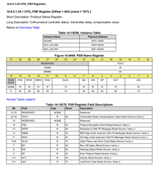
    Can you share the register dump of PSR, to find out what error was triggered?

    Regards,
    Aparna

  •       bitPos = (1U << fifoStartIdx);
          /* Poll for Tx completion */
          uint32_t mcu_PSR = 0;
          do {
            txStatus = MCAN_getTxBufTransmissionStatus(gMcanBaseAddr);
            mcu_PSR = HW_RD_REG32(0x04E18044);
            DebugP_log("mcu_PSR:0X%02x\r\n", mcu_PSR);
            appLogWaitMsecs(1000u);
          } while ((txStatus & bitPos) != bitPos);

    Result:

    [MCU1_0]   2699.930199 s: [MCAN] Loopback Polling mode, application started ...
    [MCU1_0]   2699.931499 s: mcu_PSR:0X707
    [MCU1_0]   2700.931280 s: mcu_PSR:0Xf040f
    [MCU1_0]   2701.931353 s: mcu_PSR:0Xf070f
    [MCU1_0]   2702.931431 s: mcu_PSR:0Xf070f
    [MCU1_0]   2703.931511 s: mcu_PSR:0Xf070f
    [MCU1_0]   2704.931589 s: mcu_PSR:0Xf070f
    [MCU1_0]   2705.931669 s: mcu_PSR:0Xf070f
    [MCU1_0]   2706.931746 s: mcu_PSR:0Xf070f
    [MCU1_0]   2707.931824 s: mcu_PSR:0Xf070f
    [MCU1_0]   2708.931905 s: mcu_PSR:0Xf070f
    [MCU1_0]   2709.931983 s: mcu_PSR:0Xf070f
    [MCU1_0]   2710.932060 s: mcu_PSR:0Xf070f
    [MCU1_0]   2711.932148 s: mcu_PSR:0Xf070f
    [MCU1_0]   2712.932225 s: mcu_PSR:0Xf070f
    [MCU1_0]   2713.932305 s: mcu_PSR:0Xf070f
    [MCU1_0]   2714.932381 s: mcu_PSR:0Xf070f
    [MCU1_0]   2715.932460 s: mcu_PSR:0Xf070f

    Normal: 500K ,Data:2M 

    MCAN_BitTimingParams gMcanBitTimingDefaultParams = {
        .nomRatePrescalar = 1,
        .nomTimeSeg1 = 62,
        .nomTimeSeg2 = 15,
        .nomSynchJumpWidth = 4,
    
        .dataRatePrescalar = 1,
        .dataTimeSeg1 = 14,
        .dataTimeSeg2 = 3,
        .dataSynchJumpWidth = 1,
    };

  • From the observation, looks like there are no errors triggered.

    Are you changing the MCAN instance to MCU_MCAN1 using syscfg and re-building the examples?

    By default, the example supports MCU_MCAN0 instance, hence the related configurations such as interrupt number are associated with MCU_MCAN0.

  • From the observation, looks like there are no errors triggered.

    -------maybe you are mistake.   the 1st dump the TDC is 0,the 2nd dump the DLEC is 4, that is data BIT1 error, and the TDC has changed to 0xF. in the default init code. the TDC is setup to 0.
    -------Are you changing the MCAN instance to MCU_MCAN1 using syscfg and re-building the examples?

    I will try it again. Now the strange thing is the same configuration with CAN0, CAN0 instance works well. but CAN1 does not.

  • Hi, Aprana,

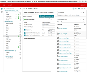
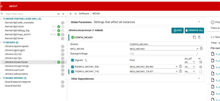
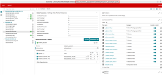
    I try open the {RTOS_SDK_PATH}/vision_apps/platform/am62a/rtos/mcu1_0/example.syscfg with sysconfig tools({RTOS_SDK}/sysconfig_1.19.0/sysconfig_gui.sh)  And re-add MCU-CAN1:

    when make sdk, the error is throw:

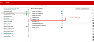
    so i disable and remove UART debug module, and keep the CAN module enable:

    the error like this:

    I don't know why.

    below is my example.config:

    /**
     * These arguments were used when this file was generated. They will be automatically applied on subsequent loads
     * via the GUI or CLI. Run CLI with '--help' for additional information on how to override these arguments.
     * @cliArgs --device "AM62Ax" --package "AMB" --part "Default" --context "mcu-r5fss0-0" --product "MCU_PLUS_SDK_AM62Ax@09.02.00"
     * @versions {"tool":"1.19.0+3426"}
     */
    
    /**
     * Import the modules used in this configuration.
     */
    const mcan       = scripting.addModule("/drivers/mcan/mcan", {}, false);
    const mcan1      = mcan.addInstance();
    const clock      = scripting.addModule("/kernel/dpl/clock");
    const debug_log  = scripting.addModule("/kernel/dpl/debug_log");
    const mpu_armv7  = scripting.addModule("/kernel/dpl/mpu_armv7", {}, false);
    const mpu_armv71 = mpu_armv7.addInstance();
    const mpu_armv72 = mpu_armv7.addInstance();
    const mpu_armv73 = mpu_armv7.addInstance();
    const mpu_armv74 = mpu_armv7.addInstance();
    const mpu_armv75 = mpu_armv7.addInstance();
    const mpu_armv76 = mpu_armv7.addInstance();
    const mpu_armv77 = mpu_armv7.addInstance();
    const mpu_armv78 = mpu_armv7.addInstance();
    const mpu_armv79 = mpu_armv7.addInstance();
    
    /**
     * Write custom configuration values to the imported modules.
     */
    mcan1.$name               = "CONFIG_MCAN1";
    mcan1.MCU_MCAN.$assign    = "MCU_MCAN1";
    mcan1.MCU_MCAN.RX.$assign = "MCU_MCAN1_RX";
    mcan1.MCU_MCAN.TX.$assign = "MCU_MCAN1_TX";
    
    mpu_armv71.allowExecute = false;
    mpu_armv71.$name        = "REGISTER_REGION";
    mpu_armv71.tex          = 0;
    mpu_armv71.isCacheable  = false;
    mpu_armv71.attributes   = "CUSTOM";
    mpu_armv71.isBufferable = false;
    
    mpu_armv72.$name       = "TCMA_VEC";
    mpu_armv72.size        = 15;
    mpu_armv72.attributes  = "CUSTOM";
    mpu_armv72.tex         = 5;
    mpu_armv72.isCacheable = false;
    
    mpu_armv73.baseAddr    = 0x80000000;
    mpu_armv73.size        = 31;
    mpu_armv73.$name       = "DDR";
    mpu_armv73.attributes  = "CUSTOM";
    mpu_armv73.tex         = 5;
    mpu_armv73.isCacheable = false;
    
    mpu_armv74.baseAddr     = 0x41010000;
    mpu_armv74.size         = 15;
    mpu_armv74.$name        = "TCMB";
    mpu_armv74.attributes   = "CUSTOM";
    mpu_armv74.isCacheable  = false;
    mpu_armv74.isBufferable = false;
    mpu_armv74.tex          = 4;
    
    mpu_armv75.baseAddr    = 0x50000000;
    mpu_armv75.$name       = "FSS_DAT";
    mpu_armv75.size        = 27;
    mpu_armv75.attributes  = "CUSTOM";
    mpu_armv75.tex         = 5;
    mpu_armv75.isCacheable = false;
    
    mpu_armv76.baseAddr     = 0x9C800000;
    mpu_armv76.size         = 21;
    mpu_armv76.$name        = "IPC_VRING_RESOURCE_TABLE_LINUX";
    mpu_armv76.attributes   = "CUSTOM";
    mpu_armv76.tex          = 0;
    mpu_armv76.isCacheable  = false;
    mpu_armv76.isBufferable = false;
    mpu_armv76.allowExecute = false;
    
    mpu_armv77.baseAddr     = 0xA0000000;
    mpu_armv77.allowExecute = false;
    mpu_armv77.$name        = "IPC_RTOS_VRING_TIOVX";
    mpu_armv77.attributes   = "CUSTOM";
    mpu_armv77.isCacheable  = false;
    mpu_armv77.isBufferable = false;
    mpu_armv77.tex          = 0;
    mpu_armv77.size         = 24;
    
    mpu_armv78.$name        = "TIOVX_RUN_TIME_LOGGING1";
    mpu_armv78.allowExecute = false;
    mpu_armv78.attributes   = "CUSTOM";
    mpu_armv78.isCacheable  = false;
    mpu_armv78.isBufferable = false;
    mpu_armv78.tex          = 0;
    mpu_armv78.baseAddr     = 0xA1000000;
    mpu_armv78.size         = 24;
    
    mpu_armv79.$name        = "TIOVX_RUN_TIME_LOGGING2";
    mpu_armv79.allowExecute = false;
    mpu_armv79.attributes   = "CUSTOM";
    mpu_armv79.isCacheable  = false;
    mpu_armv79.isBufferable = false;
    mpu_armv79.tex          = 0;
    mpu_armv79.baseAddr     = 0xA2000000;
    mpu_armv79.size         = 24;
    

    would you tell me how can I resolve this issue?

  • Hi Aparna,

    thank you for your helps.

    I have resolved this issue.

  • Hi,

    Could you please share how did you get the issue resolved?

    Regards,
    Aparna

  • yes, of course.

    Base this dumping info.

    The first dumping is normal. and the 2nd dumping is incorrect(TDC value is modified and BIT1 ERROR.). so I guess maybe that related to the TDC function. So I try to disable the TDC, then the CAN1 instance sending FD frame with BRS is well.

    Normally. when the BRS is enable and the data filed bit rate >= 2Mpbs, the TDC should enable.

    Also,before I have used TJA1051TK transceiver on the TDA4-Entry and TDA4-eco custom, but that works well with BRS when TDC is enable. I don't know why it doesn't work on AM62A.

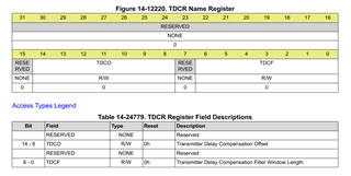
    By the way, How to calculate and configure  TDCO and TDCF in the TDCR register,  I can't find detail description in the TRM. and what is TDCF? is it a threshold for TDCO?

  • Hi,

    The Transmission Delay Compensation Value (TDCV) used as the Secondary Sample Point (SSP) is selected automatically by the CAN controller. The controller measures the delay between when a dominant signal is driven on m_can_tx to when the corresponding edge appears on m_can_rx, sampling every tq. This measured value is updated in the TDCV field of the Protocol Status Register (PSR address=h1044) at each transmission of CAN FD frame, it is used as reference and is used during the data portion of CAN FD transmission to verify good transmission. 

    The SSP that is selected by the CAN controller can be restricted to a certain window using the Transmitter Delay Compensation Offset (TDCO) and Filter Window Length (TDCF). The offset provides extra amount of time quanta to be added to the delay measurement of the CAN controller. The filter window length defines a minimum valid delay measurement, ensuring the SSP is greater than the value defined here. These values can be configured in the Transmitter Delay Compensation Register (TDCR address=h1048). 

    Regards,
    Aparna