Because of the Thanksgiving holiday in the U.S., TI E2E™ design support forum responses may be delayed from November 25 through December 2. Thank you for your patience.

PHYTC-3P-PHYBOARD-AM335X: multi-functional pin configuration issue

Part Number: PHYTC-3P-PHYBOARD-AM335X
Other Parts Discussed in Thread: AM3352

Tool/software:

Dear TI,

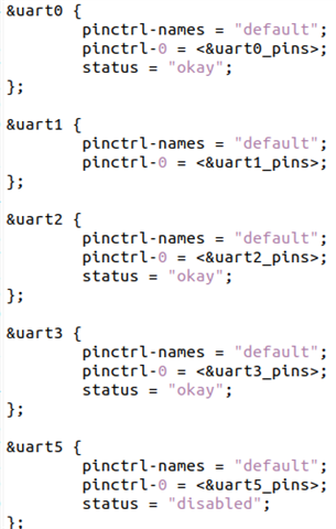
I have referred to the datasheet for the multi-functional pin configuration of UART5.

  • AM335X_PIN_MII1_COL (UART RX)
  • AM335X_PIN_LCD_DATA8 (UART TX)

After completing the configuration and loading the Kernel and DTS, the system fails to boot successfully.

Question:

Does the AM335X support this combination? According to the datasheet, it seems possible.

  • Hi Vic,

    Does the AM335X support this combination? According to the datasheet, it seems possible.

    Yes, this combination is supported.

  • Dear Bin

    During the actual execution, I discovered that the system could not boot properly when UART5 Kernel was enabled. However, the system functioned normally when UART5 Kernel was disabled.

    To analyze the issue further, I specifically created two different versions for experimentation, aiming to identify the potential causes and seek a solution.

    Finally, I raised the following question:
    Is there any method to further analyze this issue? Or do you have any suggestions that could help?

  • Hi Vic,

    During the actual execution, I discovered that the system could not boot properly when UART5 Kernel was enabled.

    How does it not boot properly? UART5 cannot transmit data or Linux boot got stuck? Please attach any Linux log to show the problem.

  • Dear Bin,

    If you need a screenshot, I may need some time to provide it later.

    The current situation is as follows:

    According to the log information, during the transition from U-Boot to the Kernel, the first log line shows no activity and appears to be stuck.

  • If you need a screenshot, I may need some time to provide it later.

    I would need you to save the boot log to a file then attach the file to this thread.

    According to the log information, during the transition from U-Boot to the Kernel, the first log line shows no activity and appears to be stuck.

    Do you use UART5 as Linux console?

    Please provide the patch of your kernel change.

  • UART5_disabled.txt
    commandline: consoleblank=0 console=ttyO0,115200n8  root=/dev/mmcblk0p2 rootflags=data=journal rootwait rw fsck.repair=yes
    [    0.000000] Booting Linux on physical CPU 0x0
    [    0.000000] Linux version 6.6.44-01448-g31f84fe16e65-dirty (meng-wei@mengwei-Ubuntu) (arm-none-linux-gnueabihf-gcc (Arm GNU Toolchain 11.3.Rel1) 11.3.1 20220712, GNU ld (Arm GNU Toolchain 11.3.Rel1) 2.38.20220708) #1 PREEMPT Tue Nov 19 08:34:05 CST 2024
    [    0.000000] CPU: ARMv7 Processor [413fc082] revision 2 (ARMv7), cr=10c5387d
    [    0.000000] CPU: PIPT / VIPT nonaliasing data cache, VIPT aliasing instruction cache
    [    0.000000] OF: fdt: Machine model: LITEON e-PTW
    [    0.000000] Memory policy: Data cache writeback
    [    0.000000] efi: UEFI not found.
    [    0.000000] cma: Reserved 64 MiB at 0xbc000000 on node -1
    [    0.000000] Zone ranges:
    [    0.000000]   Normal   [mem 0x0000000080000000-0x00000000afdfffff]
    [    0.000000]   HighMem  [mem 0x00000000afe00000-0x00000000bfffffff]
    [    0.000000] Movable zone start for each node
    [    0.000000] Early memory node ranges
    [    0.000000]   node   0: [mem 0x0000000080000000-0x00000000afdfffff]
    [    0.000000]   node   0: [mem 0x00000000b0000000-0x00000000bfffffff]
    [    0.000000] Initmem setup node 0 [mem 0x0000000080000000-0x00000000bfffffff]
    [    0.000000] On node 0, zone HighMem: 512 pages in unavailable ranges
    [    0.000000] CPU: All CPU(s) started in SVC mode.
    [    0.000000] AM335X ES2.1 (neon)
    [    0.000000] Kernel command line: consoleblank=0 console=ttyO0,115200n8  root=/dev/mmcblk0p2 rootflags=data=journal rootwait rw fsck.repair=yes
    [    0.000000] Dentry cache hash table entries: 131072 (order: 7, 524288 bytes, linear)
    [    0.000000] Inode-cache hash table entries: 65536 (order: 6, 262144 bytes, linear)
    
    UART5_okay.txt
    commandline: consoleblank=0 console=ttyO0,115200n8  root=/dev/mmcblk0p2 rootflags=data=journal rootwait rw fsck.repair=yes
    

    Dear Bin

    I provide two log files, one with logging enabled and one without, along with some descriptions of the DTS files.

  • Is the ONLY difference between the two boot tests the dtb change, one with uart5 disabled and the other with uart5 okay?

  • And the very first line of the two logs was added by you manually, not printed by the boot process, correct?

  • Dear Bin,

    This is not manually entered by me; it is a U-boot command line parameter.

    Yes, the difference between the two is "Disable" and "okay."

    I believe the datasheet is correct, which is why I raised this issue.

    Since we have already designed a customized PCBA, I mainly want to discuss the following questions:

    1. Is it possible that an actual design error in the PCBA could cause this issue?
    2. Are there any methods or tools to verify if there is a design error in the PCBA? (I have already used the Pinmux Tool Cloud for verification)
  • Hi Vic,

    This is not manually entered by me; it is a U-boot command line parameter.

    What u-boot do you use? The u-boot provided in the processor sdk doesn’t print this command line parameter before kernel starts.

    I cannot think of any reason that would cause kernel to not start at all when uart5 is enabled. You can try to remove the uart5 pinmux setting but keep uart5 enabled in kernel device tree to see if kernel still cannot boot. 

  • Dear Bin,

    I am not using the SDK's U-Boot.

    I have rebuilt using the open-source version, but it is still based on the latest TI version.

    Okay, I will try this method for verification.

  • Dear Bin

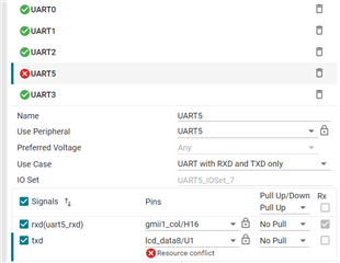
    "I also use the TI Developer Zone to modify and adjust the Pinmux, as shown in the reference image/File.

  • AM335X.syscfg

    **
    * These arguments were used when this file was generated. They will be automatically applied on subsequent loads
    * via the GUI or CLI. Run CLI with '--help' for additional information on how to override these arguments.
    * @cliArgs --device "AM335x" --part "AM3352-ZCZ" --package "ZCZ"
    * @v2CliArgs --device "AM3352" --package "FCBGA (ZCZ)"
    * @versions {"tool":"1.21.2+3837"}
    */

    /**
    * These are the peripherals and settings in this configuration
    */
    const iADC1 = scripting.addPeripheral("ADC");
    iADC1.$name = "ADC";
    iADC1.$assign = "ADC";
    iADC1.AIN0.$assign = "AIN0";
    iADC1.AIN1.$assign = "AIN1";
    iADC1.AIN2.$assign = "AIN2";
    iADC1.AIN3.$assign = "AIN3";
    iADC1.AIN4.$assign = "AIN4";
    iADC1.AIN5.$assign = "AIN5";
    iADC1.AIN6.$assign = "AIN6";
    iADC1.AIN7.$assign = "AIN7";
    iADC1.VREFN.$assign = "VREFN";
    iADC1.VREFP.$assign = "VREFP";
    const iDCAN1 = scripting.addPeripheral("DCAN");
    iDCAN1.$name = "CAN0";
    iDCAN1.$assign = "DCAN0";
    iDCAN1.rx.$assign = "uart1_rtsn";
    iDCAN1.tx.$assign = "uart1_ctsn";
    const iDEBUGSS1 = scripting.addPeripheral("DEBUGSS");
    iDEBUGSS1.$useCase = "DEBUGSS_2";
    iDEBUGSS1.$name = "JTAG";
    iDEBUGSS1.$assign = "DEBUGSS";
    iDEBUGSS1.TMS.$assign = "TMS";
    iDEBUGSS1.TDI.$assign = "TDI";
    iDEBUGSS1.TDO.$assign = "TDO";
    iDEBUGSS1.TCK.$assign = "TCK";
    iDEBUGSS1.nTRST.$assign = "nTRST";
    iDEBUGSS1.EMU0.$assign = "EMU0";
    iDEBUGSS1.EMU1.$assign = "EMU1";
    iDEBUGSS1.EMU2.$assign = "xdma_event_intr0";
    const iEMIF1 = scripting.addPeripheral("EMIF");
    iEMIF1.$useCase = "EMIF_3";
    iEMIF1.$name = "EMIF1";
    iEMIF1.$assign = "EMIF4";
    iEMIF1.resetn.$assign = "ddr_resetn";
    iEMIF1.csn0.$assign = "ddr_csn0";
    iEMIF1.ck.$assign = "ddr_ck";
    iEMIF1.nck.$assign = "ddr_nck";
    iEMIF1.casn.$assign = "ddr_casn";
    iEMIF1.rasn.$assign = "ddr_rasn";
    iEMIF1.wen.$assign = "ddr_wen";
    iEMIF1.ba0.$assign = "ddr_ba0";
    iEMIF1.ba1.$assign = "ddr_ba1";
    iEMIF1.ba2.$assign = "ddr_ba2";
    iEMIF1.a0.$assign = "ddr_a0";
    iEMIF1.a1.$assign = "ddr_a1";
    iEMIF1.a2.$assign = "ddr_a2";
    iEMIF1.a3.$assign = "ddr_a3";
    iEMIF1.a4.$assign = "ddr_a4";
    iEMIF1.a5.$assign = "ddr_a5";
    iEMIF1.a6.$assign = "ddr_a6";
    iEMIF1.a7.$assign = "ddr_a7";
    iEMIF1.a8.$assign = "ddr_a8";
    iEMIF1.a9.$assign = "ddr_a9";
    iEMIF1.a10.$assign = "ddr_a10";
    iEMIF1.a11.$assign = "ddr_a11";
    iEMIF1.a12.$assign = "ddr_a12";
    iEMIF1.a13.$assign = "ddr_a13";
    iEMIF1.a14.$assign = "ddr_a14";
    iEMIF1.a15.$assign = "ddr_a15";
    iEMIF1.d0.$assign = "ddr_d0";
    iEMIF1.d1.$assign = "ddr_d1";
    iEMIF1.d2.$assign = "ddr_d2";
    iEMIF1.d3.$assign = "ddr_d3";
    iEMIF1.d4.$assign = "ddr_d4";
    iEMIF1.d5.$assign = "ddr_d5";
    iEMIF1.d6.$assign = "ddr_d6";
    iEMIF1.d7.$assign = "ddr_d7";
    iEMIF1.d8.$assign = "ddr_d8";
    iEMIF1.d9.$assign = "ddr_d9";
    iEMIF1.d10.$assign = "ddr_d10";
    iEMIF1.d11.$assign = "ddr_d11";
    iEMIF1.d12.$assign = "ddr_d12";
    iEMIF1.d13.$assign = "ddr_d13";
    iEMIF1.d14.$assign = "ddr_d14";
    iEMIF1.d15.$assign = "ddr_d15";
    iEMIF1.dqm0.$assign = "ddr_dqm0";
    iEMIF1.dqm1.$assign = "ddr_dqm1";
    iEMIF1.dqs0.$assign = "ddr_dqs0";
    iEMIF1.dqsn0.$assign = "ddr_dqsn0";
    iEMIF1.dqs1.$assign = "ddr_dqs1";
    iEMIF1.dqsn1.$assign = "ddr_dqsn1";
    iEMIF1.vref.$assign = "ddr_vref";
    iEMIF1.vtp.$assign = "ddr_vtp";
    const iGPIO1 = scripting.addPeripheral("GPIO");
    iGPIO1.$name = "GPIO0";
    iGPIO1.$assign = "GPIO0";
    iGPIO1["gpio[0]"].$used = false;
    iGPIO1["gpio[1]"].$used = false;
    iGPIO1["gpio[2]"].$used = false;
    iGPIO1["gpio[3]"].$used = false;
    iGPIO1["gpio[4]"].$used = false;
    iGPIO1["gpio[5]"].$used = false;
    iGPIO1["gpio[6]"].$used = false;
    iGPIO1["gpio[7]"].$used = false;
    iGPIO1["gpio[8]"].$used = false;
    iGPIO1["gpio[9]"].$used = false;
    iGPIO1["gpio[10]"].$used = false;
    iGPIO1["gpio[11]"].$used = false;
    iGPIO1["gpio[12]"].$used = false;
    iGPIO1["gpio[13]"].$used = false;
    iGPIO1["gpio[14]"].$used = false;
    iGPIO1["gpio[15]"].$used = false;
    iGPIO1["gpio[16]"].$used = false;
    iGPIO1["gpio[17]"].$used = false;
    iGPIO1["gpio[18]"].$used = false;
    iGPIO1["gpio[19]"].$used = false;
    iGPIO1["gpio[20]"].$used = false;
    iGPIO1["gpio[21]"].$used = false;
    iGPIO1["gpio[22]"].pu_pd = "pd";
    iGPIO1["gpio[22]"].$assign = "gpmc_ad8";
    iGPIO1["gpio[23]"].$assign = "gpmc_ad9";
    iGPIO1["gpio[24]"].$used = false;
    iGPIO1["gpio[25]"].$used = false;
    iGPIO1["gpio[26]"].$assign = "gpmc_ad10";
    iGPIO1["gpio[27]"].$assign = "gpmc_ad11";
    iGPIO1["gpio[28]"].$used = false;
    iGPIO1["gpio[29]"].$used = false;
    iGPIO1["gpio[30]"].rx = false;
    iGPIO1["gpio[30]"].$assign = "gpmc_wait0";
    iGPIO1["gpio[31]"].rx = false;
    iGPIO1["gpio[31]"].$assign = "gpmc_wpn";
    const iGPIO2 = scripting.addPeripheral("GPIO");
    iGPIO2.$name = "GPIO2";
    iGPIO2.$assign = "GPIO2";
    iGPIO2["gpio[0]"].$used = false;
    iGPIO2["gpio[1]"].$used = false;
    iGPIO2["gpio[2]"].rx = false;
    iGPIO2["gpio[2]"].$assign = "gpmc_advn_ale";
    iGPIO2["gpio[3]"].rx = false;
    iGPIO2["gpio[3]"].$assign = "gpmc_oen_ren";
    iGPIO2["gpio[4]"].rx = false;
    iGPIO2["gpio[4]"].$assign = "gpmc_wen";
    iGPIO2["gpio[5]"].rx = false;
    iGPIO2["gpio[5]"].$assign = "gpmc_be0n_cle";
    iGPIO2["gpio[6]"].$used = false;
    iGPIO2["gpio[7]"].$used = false;
    iGPIO2["gpio[8]"].$used = false;
    iGPIO2["gpio[9]"].$used = false;
    iGPIO2["gpio[10]"].$used = false;
    iGPIO2["gpio[11]"].$used = false;
    iGPIO2["gpio[12]"].$used = false;
    iGPIO2["gpio[13]"].$used = false;
    iGPIO2["gpio[14]"].$used = false;
    iGPIO2["gpio[15]"].$used = false;
    iGPIO2["gpio[16]"].$used = false;
    iGPIO2["gpio[17]"].$used = false;
    iGPIO2["gpio[18]"].$used = false;
    iGPIO2["gpio[19]"].$used = false;
    iGPIO2["gpio[20]"].$used = false;
    iGPIO2["gpio[21]"].$used = false;
    iGPIO2["gpio[22]"].$used = false;
    iGPIO2["gpio[23]"].$used = false;
    iGPIO2["gpio[24]"].$used = false;
    iGPIO2["gpio[25]"].$used = false;
    iGPIO2["gpio[26]"].$used = false;
    iGPIO2["gpio[27]"].$used = false;
    iGPIO2["gpio[28]"].$used = false;
    iGPIO2["gpio[29]"].$used = false;
    iGPIO2["gpio[30]"].$used = false;
    iGPIO2["gpio[31]"].$used = false;
    const iI2C1 = scripting.addPeripheral("I2C");
    iI2C1.$useCase = "I2C_1";
    iI2C1.$name = "I2C0";
    iI2C1.$assign = "I2C0";
    iI2C1.SCL.$assign = "I2C0_SCL";
    iI2C1.SDA.$assign = "I2C0_SDA";
    const iMMC1 = scripting.addPeripheral("MMC");
    iMMC1.$useCase = "MMC_2";
    iMMC1.$name = "SD CARD";
    iMMC1.$assign = "MMC0";
    iMMC1.clk.$assign = "mmc0_clk";
    iMMC1.cmd.$assign = "mmc0_cmd";
    iMMC1.dat0.$assign = "mmc0_dat0";
    iMMC1.dat1.$assign = "mmc0_dat1";
    iMMC1.dat2.$assign = "mmc0_dat2";
    iMMC1.dat3.$assign = "mmc0_dat3";
    const iMMC2 = scripting.addPeripheral("MMC");
    iMMC2.$useCase = "MMC_5";
    iMMC2.$name = "MMC1";
    iMMC2.$assign = "MMC1";
    iMMC2.clk.pu_pd = "pd";
    iMMC2.clk.$assign = "gpmc_csn1";
    iMMC2.cmd.pu_pd = "pd";
    iMMC2.cmd.$assign = "gpmc_csn2";
    iMMC2.dat0.pu_pd = "pd";
    iMMC2.dat0.$assign = "gpmc_ad0";
    iMMC2.dat1.pu_pd = "pd";
    iMMC2.dat1.$assign = "gpmc_ad1";
    iMMC2.dat2.pu_pd = "pd";
    iMMC2.dat2.$assign = "gpmc_ad2";
    iMMC2.dat3.pu_pd = "pd";
    iMMC2.dat3.$assign = "gpmc_ad3";
    iMMC2.dat4.pu_pd = "pd";
    iMMC2.dat4.$assign = "gpmc_ad4";
    iMMC2.dat5.pu_pd = "pd";
    iMMC2.dat5.$assign = "gpmc_ad5";
    iMMC2.dat6.pu_pd = "pd";
    iMMC2.dat6.$assign = "gpmc_ad6";
    iMMC2.dat7.pu_pd = "pd";
    iMMC2.dat7.$assign = "gpmc_ad7";
    const iMMC3 = scripting.addPeripheral("MMC");
    iMMC3.$useCase = "MMC_4";
    iMMC3.$name = "MMC2";
    iMMC3.$assign = "MMC2";
    iMMC3.clk.$assign = "gpmc_clk";
    iMMC3.cmd.$assign = "gpmc_csn3";
    iMMC3.dat0.$assign = "gpmc_ad12";
    iMMC3.dat1.$assign = "gpmc_ad13";
    iMMC3.dat2.$assign = "gpmc_ad14";
    iMMC3.dat3.$assign = "gpmc_ad15";
    const iRGMII1 = scripting.addPeripheral("RGMII");
    iRGMII1.$useCase = "RGMII_1";
    iRGMII1.$name = "RGMII1";
    iRGMII1.$assign = "RGMII1";
    iRGMII1.tctl.$assign = "gmii1_txen";
    iRGMII1.rctl.$assign = "gmii1_rxdv";
    iRGMII1.tclk.$assign = "gmii1_txclk";
    iRGMII1.rclk.$assign = "gmii1_rxclk";
    iRGMII1.td0.$assign = "gmii1_txd0";
    iRGMII1.td1.$assign = "gmii1_txd1";
    iRGMII1.td2.$assign = "gmii1_txd2";
    iRGMII1.td3.$assign = "gmii1_txd3";
    iRGMII1.rd0.$assign = "gmii1_rxd0";
    iRGMII1.rd1.$assign = "gmii1_rxd1";
    iRGMII1.rd2.$assign = "gmii1_rxd2";
    iRGMII1.rd3.$assign = "gmii1_rxd3";
    const iRGMII2 = scripting.addPeripheral("RGMII");
    iRGMII2.$useCase = "RGMII_1";
    iRGMII2.$name = "RGMII2";
    iRGMII2.$assign = "RGMII2";
    iRGMII2.tctl.$assign = "gpmc_a0";
    iRGMII2.rctl.$assign = "gpmc_a1";
    iRGMII2.tclk.$assign = "gpmc_a6";
    iRGMII2.rclk.$assign = "gpmc_a7";
    iRGMII2.td0.$assign = "gpmc_a5";
    iRGMII2.td1.$assign = "gpmc_a4";
    iRGMII2.td2.$assign = "gpmc_a3";
    iRGMII2.td3.$assign = "gpmc_a2";
    iRGMII2.rd0.$assign = "gpmc_a11";
    iRGMII2.rd1.$assign = "gpmc_a10";
    iRGMII2.rd2.$assign = "gpmc_a9";
    iRGMII2.rd3.$assign = "gpmc_a8";
    const iSPI1 = scripting.addPeripheral("SPI");
    iSPI1.$name = "SPI1";
    iSPI1.$assign = "SPI0";
    iSPI1.SCLK.$assign = "spi0_sclk";
    iSPI1.SCLK.$used = false;
    iSPI1.D0.$assign = "spi0_d0";
    iSPI1.D1.$assign = "spi0_d1";
    iSPI1.CS0.$assign = "spi0_cs0";
    iSPI1.CS1.$assignAllowConflicts = "spi0_cs1";
    iSPI1.CS1.$used = false;
    const iUART1 = scripting.addPeripheral("UART");
    iUART1.$useCase = "UART_1";
    iUART1.$name = "UART0";
    iUART1.$assign = "UART0";
    iUART1.rxd.$assign = "uart0_rxd";
    iUART1.txd.$assign = "uart0_txd";
    const iUART2 = scripting.addPeripheral("UART");
    iUART2.$useCase = "UART_1";
    iUART2.$name = "UART1";
    iUART2.$assign = "UART1";
    iUART2.rxd.$assign = "uart1_rxd";
    iUART2.txd.$assign = "uart1_txd";
    const iUART3 = scripting.addPeripheral("UART");
    iUART3.$useCase = "UART_1";
    iUART3.$name = "UART2";
    iUART3.$assign = "UART2";
    iUART3.rxd.$assign = "gmii1_crs";
    iUART3.txd.$assign = "gmii1_rxer";
    const iUART4 = scripting.addPeripheral("UART");
    iUART4.$useCase = "UART_1";
    iUART4.$name = "UART5";
    iUART4.$assign = "UART5";
    iUART4.rxd.$assign = "gmii1_col";
    iUART4.txd.$assign = "lcd_data8";
    const iUART5 = scripting.addPeripheral("UART");
    iUART5.$useCase = "UART_1";
    iUART5.$name = "UART3";
    iUART5.$assign = "UART3";
    iUART5.rxd.$assign = "spi0_cs1";
    iUART5.txd.$assign = "eCAP0_in_PWM0_out";
    const iUSB1 = scripting.addPeripheral("USB");
    iUSB1.$useCase = "USB_1";
    iUSB1.$name = "USB0";
    iUSB1.$assign = "USB0";
    iUSB1.CE.$used = false;
    iUSB1.DM.$assign = "USB0_DM";
    iUSB1.DP.$assign = "USB0_DP";
    iUSB1.DRVVBUS.$assign = "USB0_DRVVBUS";
    iUSB1.ID.$assign = "USB0_ID";
    iUSB1.VBUS.$assign = "USB0_VBUS";
    const iUSB2 = scripting.addPeripheral("USB");
    iUSB2.$useCase = "USB_1";
    iUSB2.$name = "USB1";
    iUSB2.$assign = "USB1";
    iUSB2.CE.$assign = "USB1_CE";
    iUSB2.DM.$assign = "USB1_DM";
    iUSB2.DP.$assign = "USB1_DP";
    iUSB2.DRVVBUS.$assign = "USB1_DRVVBUS";
    iUSB2.ID.$assign = "USB1_ID";
    iUSB2.VBUS.$assign = "USB1_VBUS";

    /**
    * Pinmux solution for unlocked pins/peripherals. This ensures that minor changes to the automatic solver in a future
    * version of the tool will not impact the pinmux you originally saw. These lines can be completely deleted in order to
    * re-solve from scratch.
    */
    iUART4.txd.$suggestSolution = "<error>";

  • Hi Vic,

    Does the AM335X support this combination? According to the datasheet, it seems possible.

    Yes, this combination is supported.

    I think I misspoke. The Pinmux tool shows both H16 and U1 pins cannot be used together for UART5 mode, it shows "Resource conflict" error.