SK-AM62A-LP: Add new sensor support in ISP

Part Number: SK-AM62A-LP

Tool/software:

Hello,

We are using ar0235 onsemi sensor, in that we are able to successfully video stream. but we want to add support in isp of gsttiovxisp.c file that support our sensor.

In gsttiovxisp.c file "gst_tiovx_isp_map_2A_values" function has calculation of exposure_time_mapped and analog_gain_mapped based on existing supported sensor.
We want to add calculation of exposure and gain for auto exposure mode based on ar0235 sensor.

Path of file : ../aarch64-oe-linux/edgeai-gst-plugins/AUTOINC+92557180c3-r0_edgeai_0/git/ext/tiovx/gsttiovxisp.c

Can you please guide me or if any document available to how to we calculate exposure and gain for auto exposure mode in isp.

sensor support:

Resolution 1920x1200
exposure range : min=0 max=420000
analogue_gain : min=0 max=48
fps: 30 and 60

Thanks,
Jaimin

  • Hi Jaimin,

    Please refer to the AM6xA ISP Tuning Guide, chapter 5.4.2 Add Exposure Setting for 2A Algorithm. 

    Regards,

    Jianzhong

  • Thanks Jianzhong.

    We are validating auto and manual exposure of isp and exposure and gain value we are validating in dcc imaging tool.
    We are not observing changes in gain and exposure in dcc tool and we are using AR0235 monochrome sensor.

    We have added sensor support based on AM6x ISP tunning guide.

    What will be the reason to not getting changes in tool ? We are using monochrome sensor.
     

    Also, Can you explain us more on How DCC tool find outs the exposure and gain of the sensor?

    Regards,

    Jaimin

  • Hi Jaimin,

    Please make sure you rebuild edgeai-tiovx-modules with live tuning enabled, as described in chapter 9 Live Tuning. Once you do that, the DCC live tuning tool can exchange the exposure and white balance parameters with the imaging library, through the remote service function: https://git.ti.com/cgit/processor-sdk/imaging/tree/itt_server_remote/src/itt_srvr_remote.c?h=main#n71. 

    Regards,

    Jianzhong

  • Hello Jianzhong,

    We have added support based on Tunning guide. in that with auto exposure of ISP we are able to get exposure and gain value in dcc tool but we are not getting accurate value. values are fluctuating.
    We are tunning sensor with different light condition.

    We have added below code in ext/tiovx/gsttiovxisp.c file

    static int32_t
    get_ar0235_ae_dyn_params (IssAeDynamicParams * p_ae_dynPrms)
    {
      int32_t status = -1;
      uint8_t count = 0;
    
      g_return_val_if_fail (p_ae_dynPrms, status);
    
      p_ae_dynPrms->targetBrightnessRange.min = 40;
      p_ae_dynPrms->targetBrightnessRange.max = 50;
      p_ae_dynPrms->targetBrightness = 45;
      p_ae_dynPrms->threshold = 1;
      p_ae_dynPrms->enableBlc = 1;
      p_ae_dynPrms->exposureTimeStepSize = 1;
    
      p_ae_dynPrms->exposureTimeRange[count].min = 100;
      p_ae_dynPrms->exposureTimeRange[count].max = 420000;
      p_ae_dynPrms->analogGainRange[count].min = 1024;
      p_ae_dynPrms->analogGainRange[count].max = 8192;
      p_ae_dynPrms->digitalGainRange[count].min = 256;
      p_ae_dynPrms->digitalGainRange[count].max = 256;
      count++;
    
      p_ae_dynPrms->numAeDynParams = count;
      status = 0;
      return status;
    }


    static void
    gst_tiovx_isp_map_2A_values (GstTIOVXISP * self, int exposure_time,
        int analog_gain, gint32 * exposure_time_mapped, gint32 * analog_gain_mapped)
    {
    	else if (g_strcmp0 (self->sensor_name, "ONSEMI_AR0235") == 0) 
    	{
        double multiplier = 0;
        *exposure_time_mapped = (exposure_time * 1671 * 60 / 1000000);
        //*analog_gain_mapped = analog_gain / 64;
        multiplier = analog_gain / 1024.0;
        *analog_gain_mapped = 256.0 - 256.0 / multiplier;
    }


    Can you please help in calculation if we are doing wrong ?

    Thanks,
    Jaimin

  • Hi Jaimin,

    You max exposure time doesn't look correct:

    p_ae_dynPrms->exposureTimeRange[count].max = 420000;

    This is 420msec. Usually your max exposure time is your frame duration. What is your frame rate?

    Regards,

    Jianzhong

  • Hi Jianzhong,

    I am from Jaimin's team.

    What is your frame rate?

    Sensor has 120fps maximum. But we would be using sensor at 60 fps.

    Regards,

    Jay

  • Hi Jay,

    If you're using 60fps, the exposureTimeRange[count].max should not be more than 16666 (micro-second).

    Regards,

    Jianzhong

  • Hi Jianzhong,

    Thanks for reply.

    I got your point. Exposure should be (1000ms/fps). After doing this change, we were getting gain and exposure value realistic but the gain and exposure value getting change for same lighting condition. Whereas for IMX219 sensor, gain and exposure stays same for the same lighting condition. 

    Please check below attached video for our sensor where gain and exposure changes on refresh in DCC tool for same light condition. How can be get stable gain and exposure for same light condition.

    DCC-Tool-Exposure-Gain.zip

    Regards, 

    Jay

  • Hi Jay,

    When you observed changing exposure and gain, did the image brightness look stable?

    Do you know how many frames it takes the sensor to apply the exposure and gain, for example, is it 2 frames, 3 frames, etc?

    Regards,

    Jianzhong

  • Hi Jaimin,

    Are you sure if the mapping below are correct for your AR0235 sensor driver?

        *exposure_time_mapped = (exposure_time * 1671 * 60 / 1000000);
        //*analog_gain_mapped = analog_gain / 64;
        multiplier = analog_gain / 1024.0;
        *analog_gain_mapped = 256.0 - 256.0 / multiplier;

    AE won't converge if exposure time and gain are not programed correctly in the sensor.

  • Hi Jianzhong & Gang,

    When you observed changing exposure and gain, did the image brightness look stable?

    No, image brightness doesn't look stable in stream.

    Are you sure if the mapping below are correct for your AR0235 sensor driver?

    This was wrong i guess. Then we have changed this exposure as below for 60fps.

        *exposure_time_mapped = (1200 * exposure_time / 16);
    
        multiplier = analog_gain / 1024.0;
        *analog_gain_mapped = 256.0 - 256.0 / multiplier;

    Regards,

    Jay

  • Hi Jay,

    The sensor register information may be under NDA (I don't have that available) and we cannot discuss about it publicly.

    Please check AR0235 datasheet to see if the mapping from exposure time in us and gain in Q10 integer are mapped to sensor register values properly.

  • Hi Gang Hua, 


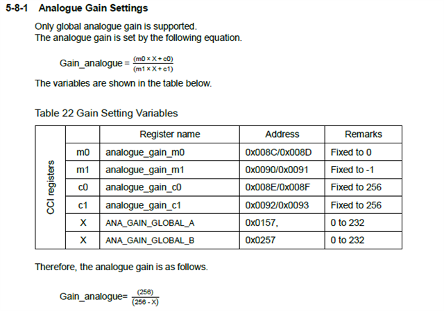
    How is the the value 256 derived in the gst_tiovx_isp_map_2A_values() for imx219 sensor in ext/tiovx/gsttiovxisp.c file for analogue gain calculationI want to derive this constant value for our camera sensor.

    Regards,

    Jay

  • Hi Jay,

    The gain mapping formula is based on the IMX219 sensor data sheet.

    Regards,

    Jianzhong

  • Hello Jianzhong,

    64 value is common for all the sensors or Is it different for each sensors ?

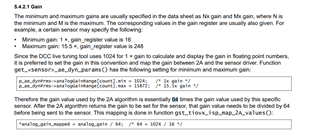
    Because every sensor has different s Nx gain and Mx gain values, where N is the minimum and M is the maximum. Based on that value we have added below data in "ext/tiovx/gsttiovxisp.c" file for custom sensors. below logic is correct  or not ? Please provide you input on it.

    p_ae_dynPrms->analogGainRange[count].min = Nx * 1024;

    p_ae_dynPrms->analogGainRange[count].max = Mx * 1024; 

    2A algorithm returns the gain. How do we set that gain value in sensors ? How do we mapped "analog_gain_mapped" value and 2A algorithm gain value? How do we convert that value and write that converted value in sensor using "ioctl" ?

    For that conversion in TI-Document mentioned 64 value as divider to convert that 2A algorithm analog gain value into sensor-gain value. But our question is, 64 value is common for all the sensors ? If not then and if it sensor specific in that case how do we derive that value for sensor specific ?

    Please provide your input on above queries asap.

    Thanks,

    Nisarg

  • Hi Nisarg,

    64 value is common for all the sensors or Is it different for each sensors ?

    That is sensor and sensor driver dependent.

    Because every sensor has different s Nx gain and Mx gain values, where N is the minimum and M is the maximum. Based on that value we have added below data in "ext/tiovx/gsttiovxisp.c" file for custom sensors. below logic is correct  or not ?

    That is a decision for AE to use a certain range of available gain on the sensor.
    It is typically not the full range available.

    2A algorithm returns the gain. How do we set that gain value in sensors ?

    In general, sensor driver has an interface ioctl for changing sensor exposure and gain values.

    AE output gain must be converted to the correct encoding for ioctl first and then invoke the ioctl for sending it to sensor.

    For that conversion in TI-Document mentioned 64 value as divider to convert that 2A algorithm analog gain value into sensor-gain value. But our question is, 64 value is common for all the sensors ?

    No, it is not common.

    If not then and if it sensor specific in that case how do we derive that value for sensor specific ?

    You would have to check your sensor interface ioctl to understand its way of encoding sensor gain and then you can map the 2A gain into the ioctl gain format.