SK-AM62A-LP: Capture Interrupt in Timer

Part Number: SK-AM62A-LP

Tool/software:

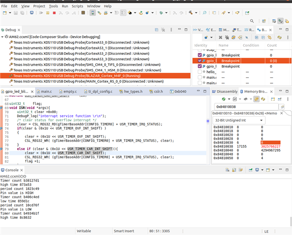
Not Able to Generate Capture Interrupt using MCU_Timer_IO1, although all the timer configuring registers are updated accordingly as you can see ..


But interrupt is not being generated even though pulse that is being passed is correctly reflecting (checked via gpio read), Also overflow interrupt is generating according to overflow but capture isn't.


 

  • Hi Sai,

    Thanks for your query.

    Can you please tell us which version of MCU+SDK are you using?

    Is the interrupt registered properly? Can you please share the code with us?

    Regards,

    Tushar

  • mcu_plus_sdk_am62x_09_02_01_06
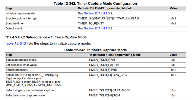
    Yes Interrupt has been registered properly followed the steps from TRM

    You can see in the screenshot in 32-uint) that TCLR 0x38 has value 0100 0011 0000 0011 set according to above configuration
    and 0x2C has 6 110 both overflow and capture are set even though overflow interrupt was triggering capture event was not getting triggered .

  • Hi Sai,

    I have tried to configure the MCU_Timer0 and I am able to generate the interrupt successfully.

    Please refer the below code for reference.

    Project - timer_am62x_m4fss0-0_nortos_ti-arm-clang.zip

    Please let us know if the above works.

    Regards,

    Tushar

  • I meant in interrupt we have several modes overflow mode,capture mode and compare mode I was able to generate the overflow interrupt but not the capture interrupt where when a pulse is connected it triggers interrupt on edges based on above configuration provided in TRM.

  • Hi Tushar ,

    Is there any update on this?

  • Hi Sai,

    Can you please provide sample code to replicate the issue?

    Regards,

    Tushar

  • #include <stdio.h>
    //#include <hw_types.h>
    #include <kernel/dpl/DebugP.h>
    #include "ti_drivers_config.h"
    #include "ti_drivers_open_close.h"
    #include "ti_board_open_close.h"
    #include <drivers/gpio.h>
    
    
    void TimerP_isr0(void *args);
    void Print();
    void Capt_init(uint32_t baseAddr);
    void Capt_enable(uint32_t baseAddr);
    void TimerWaitForWrite(uint32_t reg, uint32_t baseAddr);
    uint32_t TIMERWritePostedStatusGet(uint32_t baseAddr);


    #define USR_TIMER_IRQ_STATUS        (0x28U)
    #define USR_TIMER_IRQ_STATUS_SET    (0x2CU)
    #define USR_TIMER_IRQ_STATUS_CLEAR  (0x30U)
    #define USR_TIMER_TCLR              (0x38U)
    #define USR_TIMER_TCAR1             (0x50U)
    #define USR_TIMER_TCAR2             (0x58U)
    #define USR_TIMER_CAR_INT_SHIFT     (0x02)
    #define USR_TIMER_TSICR             (0x54U)
    #define USR_TIMER_TWPS              (0x48U)
    #define USR_TIMER_OVF_INT_SHIFT     (0x1)
    #define USR_TIMER_TLDR              (0x40U)
    
    #define TIMER_TSICR_POSTED_SHIFT    (2U)
    #define TIMER_TSICR_POSTED_MASK     (0x00000004U)
    #define TIMER_WRITE_POST_TCLR       0x01
    #define TIMER_WRITE_POST_TLDR       0x02
    
    
    /* GPIO PIN Macros */
    #define GPIO_LED_BASE_ADDR (CSL_MCU_GPIO0_BASE)
    #define GPIO_LED_PIN (1)
    #define GPIO_LED_DIR (GPIO_DIRECTION_INPUT)
    #define GPIO_LED_TRIG_TYPE (GPIO_TRIG_TYPE_NONE)
    #define CONFIG_GPIO_NUM_INSTANCES (1U)
    
    
    volatile uint32_t capone;
    volatile uint32_t captwo;
    
    uint32_t state = 0U;
    uint32_t Flag = 0U;
    uint32_t count = 0U;
    uint32_t gpioBaseAddr, pinNum,pinValue;
    
    
    void empty_main(void *args)
    {
        /* Open drivers to open the UART driver for console */
        while(1)
        {
            switch(state)
            {
              case 0U:
                Capt_init(gTimerBaseAddr[MCU_TIMER1]);
              break;
              case 1U:
                Capt_enable(gTimerBaseAddr[MCU_TIMER1]);
              break;
              case 2U:
                Print();
              break;
            }
         }
    
        DebugP_log("All tests have passed!!\r\n");
    
    }
    void Timer_ISR(void *args)
    {
        uint32_t clear =0x00;
        /* clear status for overflow interrupt */
        clear = CSL_REG32_RD(gTimerBaseAddr[MCU_TIMER1] + USR_TIMER_IRQ_STATUS);
        if(clear & (0x1U << USR_TIMER_OVF_INT_SHIFT) )
        {
            clear = (0x1U << USR_TIMER_OVF_INT_SHIFT);
            CSL_REG32_WR( (gTimerBaseAddr[MCU_TIMER1] + USR_TIMER_IRQ_STATUS), clear);
        }
    
        else if(clear & (0x1U << USR_TIMER_CAR_INT_SHIFT) )
        {
            clear = (0x1U << USR_TIMER_CAR_INT_SHIFT) ;
    
            /*read current capture value and gpio pin value */
            capone = CSL_REG32_RD(gTimerBaseAddr[MCU_TIMER1] + USR_TIMER_TCAR1);
            /*clear this interrupt */
            CSL_REG32_WR( (gTimerBaseAddr[MCU_TIMER1] + USR_TIMER_IRQ_STATUS), clear);
            Flag = 1U;
        }
    }
    
    inline void Print()
    {
        if(Flag == 1U)
        {
            DebugP_log("timer capture one = %x \r\n", capone);
            Flag = 0U;
        }
    }
    void Capt_init(uint32_t baseAddr)
    {
        volatile uint32_t *addr;
        uint32_t ctrlVal = 0x00;
        uint32_t loadVal = 0x00;
    
        addr = (volatile uint32_t *)(baseAddr + USR_TIMER_TCLR);
        //ctrlVal=((1<<13U) | (1<<14U) | (1<<1U) | (1<<9U));
        ctrlVal=( (1<<14U) | (1<<1U) | (1<<8U));
    
        CSL_REG32_WR(addr,ctrlVal);
        DebugP_log("Trigger on first event capture, gpo_cfg, enable Auto Reload Mode , enable rising edge trigger %d\r\n", ctrlVal);
        /* Wait for previous write to complete */
        TimerWaitForWrite(TIMER_WRITE_POST_TCLR, gTimerBaseAddr[MCU_TIMER1]);
        // set Load register to 0x00
        CSL_REG32_WR(baseAddr + USR_TIMER_TLDR,loadVal);
        //Wait for the write to complete
        TimerWaitForWrite(TIMER_WRITE_POST_TLDR, gTimerBaseAddr[MCU_TIMER1]);
        state = 1U;
    }
    void Capt_enable(uint32_t baseAddr)
    {
        /*** Enable capture mode ***/
        DebugP_log("Enable capture mode \r\n");
        volatile uint32_t *regaddr;
        uint32_t Value = 0x00;
    
        //set capture interrupt-enable bit
        regaddr = (volatile uint32_t *)(baseAddr + USR_TIMER_IRQ_STATUS_SET);
        Value |= 1<<2U;
        CSL_REG32_WR(regaddr,Value);
        TimerP_start(gTimerBaseAddr[MCU_TIMER1]);
        DebugP_log("Started timer \r\n");
    
        DebugP_log("Enable intr %d\r\n", Value);
        state = 2U;
    }
    void TimerWaitForWrite(uint32_t reg, uint32_t baseAddr)
    {
        if (0U != HW_RD_FIELD32(baseAddr + USR_TIMER_TSICR, TIMER_TSICR_POSTED))
        {
            while ((uint32_t) 0U != (reg & TIMERWritePostedStatusGet(baseAddr)))
            {
            
            }
        }
    }
    
    uint32_t TIMERWritePostedStatusGet(uint32_t baseAddr)
    {
        return (HW_RD_REG32(baseAddr + USR_TIMER_TWPS));
    }
    

  • Hi Tushar,

    Were you able to recreate the issue?