This thread has been locked.

If you have a related question, please click the "Ask a related question" button in the top right corner. The newly created question will be automatically linked to this question.

AM6442: Reducing jitter on a software-generated Pulse signal

Part Number: AM6442

Tool/software:

Hello Nick, Anil, team,

As agreed bringing this discussion to external thread. Summery below of current situation.

The current status:
* we have a hardware timer
* we use an interrupt on the R5
* which triggers a GPIO write

Sadly, we see in real-world applications sometimes a delay of this GPIO trigger in the area of 200-300ns. Which is the typical time we have also seen, that other processes on the AM64 are delayed, probably due to the shared bus.

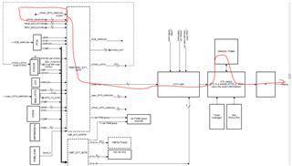
We are looking now to utilize the DMA for this process:
* So we would need a DMA transfer to write to the GPIO register
* This DMA should be triggered by the hardware timer module
* We also have the timer signal routed into the HW_TSxPUSH pin (in case this is of any help)

Can the timer interrupt or the HW_TSxPUSH signal can trigger the DMA to write to the GPIO module?

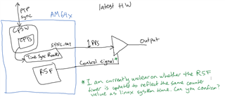
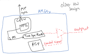
Right now, we already use the CPTS modules:
* CPTS inside GMAC for generating the PTP PPS
* global CPTS to measure synchronization accuracy and comparing PPS signals
* We already route the generated PPS through one of the SYNCx_OUT pins

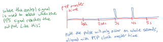
For our current application:
* As of legacy reasons, our current boards, we connect to the AM64, require a trigger signal on the UART line
* For this purpose, we generate a GPIO falling edge via the R5 interrupt from the reference PPS (AM64 Timer Module)
* If only the main R5 is being active, we see almost no jitter (close to +/-5ns, which is expected due to the 200MHz GPIO clock), as we use only TCM memory for any code or data and disable all other (FreeRTOS) interrupts
* As soon as we have some more background activities (daisy-chained devices, some network traffic), we sometimes see jumps in those delays

We already have added a multiplexer to route the actual PPS signal to the UART line, which resolves the problem on new hardware. We are just looking through, if we could still resolve the issue on existing hardware or at least improve it. For this we thought, we could use the DMA to use the memory bus a bit more efficiently and reduce the latency.

* There are several nice R5 examples of the UDMA usage

* What I'm not sure from the documentation is, how we can trigger the DMA transfer via some sort of PPS signal (we have all required PPS signals running through the TSR, as they are connected to the HWx_TS_PUSH pins)

The FAQ below helps how to trigger DMA based on the GPIO.

https://e2e.ti.com/support/processors-group/processors/f/processors-forum/1378150/faq-how-to-trigger-dma-with-the-help-of-gpio-on-am64x-am243-and-am62x-devices

Thanks,

Aida

  • Hello,

    Anil and I are not confident that we correctly understand your system. So before we discuss any implementation details, let's take a step back and make sure we understand what you are trying to do.

    The "newer" system 

    This is my current understanding of the "newer" hardware system. Is it correct? Is there anything I got wrong, or any other information you want to give us?

    The "older" system 

    Based on that understanding of the "newer" hardware, this is what I think you are trying to do with the "older" hardware. Is it correct? Is there any other information you want to give us?

    Additional questions 

    1) In the "older" hardware system, can you route the pulse out of any processor pin, only 1 processor pin, or several different processor pins? Which pin or pins can be used?

    2) I think I misunderstood what your output signal looks like. A PPS signal will only have a falling transition once per second, but I assume that your UART trigger signal should be flexible enough to be able to have a falling transition at some other time (if needed). Am I missing something?

    Regards,

    Nick

  • Currently we have a Uart TX line which is switched between (E14)

    • UART1_TXD (for typical UART communication)
    • GPIO1_57 (for sending a falling edge to the device as synchronization)

    On the newer hardware, we route the PPS signal to that signal (as you also showed in your picture), but we are looking for a solution on existing boards. On the other PCBs we have in play, we need to achieve the same thing, but have different pins (different UART peripherals).

    We need to trigger ANY sort of falling edge, as long as it's time has low jitter and is source from a timer time sync router signal. As we (almost) do not care, when exactly that edge is, as long as we know the time. We do care strongly about a constistent, low jitter time here. So target is +/-10ns to +/-20ns. Right now the bus arbitration can take 200-300ns and shift the actual GPIO falling edge by that period.

    So our proposed method to possibly have reduced jitter by using the DMA:

    • We have some timer interrupt (does NOT have to be periodic, one-shot is enough. We can synchronize that timer internally to another one with a known absolute time)
    • The timer interrupt triggers a DMA transaction
    • The DMA writes to one of those:
      • GPIO_SET_DATAxx register to trigger the falling edge (32-bit register)
      • UART_THR register to send a value of 0x00 (32-bit register, only 8-bit relevant)

    Right now we would like to evaluate, if that would improve our time accuracy. But we can't just trigger the DMA by the R5 core directly, as we also would have a memory access from R5 core, which has the same bus arbitration problem.

  • The DMA writes to one of those:
    • GPIO_SET_DATAxx register to trigger the falling edge (32-bit register)
    • UART_THR register to send a value of 0x00 (32-bit register, only 8-bit relevant)

    Hello Wolfgang Pretl,

    As I mentioned in the call, the DMA is triggered through the Timer PWM and this can be writable on the GPIO Data register .

    But, in your case, you need to trigger DMA for one shot mode and this is not possible with the timer PWM .Since, the Timer PWM is needed Auto reload .

    And, I explained about the GPIO method, and we need to control GPIO from low to high or high to low to trigger DMA but again GPIO controlling is adding delay to trigger DMA.

    And, another method is that I highlighted some inputs from CPST and CPSW Hw push and we can also trigger DMA from these inputs.

    Other than these methods, we can't trigger DMA and one more thing is you need to trigger DMA for 32bit and again here DMA is needed for  minimum of 32 bytes is required to transfer data. 

    Regards,

    Anil.