This thread has been locked.

If you have a related question, please click the "Ask a related question" button in the top right corner. The newly created question will be automatically linked to this question.

SK-AM64B: PRU GPIO Output Not Working

Part Number: SK-AM64B
Other Parts Discussed in Thread: SYSCONFIG, AM6442

Tool/software:

My PRU GPO10 output isn't working and I don't know why.

I am new to PRU and multicore programming on TI products, so throughout this post I will try to highlight assumptions I am making - please correct anything you see as wrong! I am keen to understand this system better.


My ultimate end goal is to read a Sigma-Delta ADC signal with the PRU and get that data into Linux process on the A53 cores, with some processing in the R5F cores along the way. I think I can largely copy code from the AM243x motor control examples.
Assumption 0: After changing from some memory mappings, code written for the AM243x can also run on the R5F and PRU cores as they are basically the same.
My first baby step is to step through a PRU program with the debugger, and see a GPIO pin toggle both from the CCS Debug Register window, and on an oscilloscope.
Assumption 1: It is possible to simultaneously debug an R5F core and a PRU at the same time.


The Setup

Development Software

CCS v12.8
TI ARM compiler v20.2.7
TI PRU Compiler v2.3.3
MCU+ SDK AM64x v09.02.01
Windows 11
XDS110 USB Debug Probe

The Board

SK-AM64B HS-FS
Boot mode: OSPI
Bootloader: SBL-NULL (On power-cycle the Standard COM serial output says "Starting NULL Bootloader ...)
DMSC Firmware v09.02.08, ABI revision 3.1
I have an oscilloscope measuring across pins 47 (DGND) and 53 (PRG0_PRU0GPO10) on the PRU connector (J10).

System Setup

I followed the "Getting Started" section of the MCU+ SDK docs.
I installed CCS and the MCU+ SDK to their default locations (C:\ti) and created the Target configuration for my board. I'll call this the "manually created Target Config" hereafter. The only cores I bypassed were the PRUs in ICSSG1 and M4F.
Before this work, I had been booting Linux from an SD card, so first I removed the card. Following the "EVM Setup" section of the MCU+ SDK docs, I flashed the "SOC initialization binary" to the SK.  After switching the boot mode to OSPI, I saw the NULL Bootloader output in the UART terminal, as shown in the docs. I also followed the notes after the "Attention" block about unnecessary GEL files when developing with SBL NULL. I modified the Target Configuration I created above. Note: Every time I clear the "initialization script" field under the Cortex A53_0 CPU Properties, CCS repopulated it with "..\CCSTargetConfigurations". Not sure if this is an issue.
Then, I ran the Hello World app following the Build a Hello World example instructions and the CCS Launch, Load, and Run instructions, and it worked fine.

The Application

I started with the PRU IO Empty Project. I imported the empty_pru_io_am64x-evm_r5fss0_freertos_ti-arm-clang and empty_am64x-evm_icssg0-pru0_fw_ti-pru-cgt projects from the "examples/pru_io/empty" directory of the MCU+ SDK. I noticed that the included targetConfig in each of these projects has "AM64x_GP_EVM" under "Board or Device", so I changed that to "AM64x_SK_EVM" for both the PRU and R5F projects. I also changed the GEL files in each targetConfig to match those changes described at the end of the "EVM Setup" section I mention above.

Following "Steps to Run the Example" of PRU IO Empty Project, I first built the PRU project, then built the R5F project. These steps then say I should "Launch a CCS debug session and run the executable, see CCS Launch, Load and Run". Those instructions say to use the manually created Target Config, so I did that.

Assumption 3: In this dual-CCS-project example, a copy of the built PRU binary is stored as "pru0_load_bin.h" in a folder that the R5F project has access to, so the built R5F binary has the PRU binary baked into it, which the R5F drivers load into the PRU at runtime.

To debug the empty project, I need to launch my manually created Target Configuration, connect to and reset both the R5_0_0 and ICSS_G0_PRU_0 cores, and then I use the "Run > Load..." tab in CCS to load the the binaries to the R5F and PRU, respectively. I can then step through code on both the R5F and PRU, and it seems to work.

Trying GPIO

A line in the PRU IO Empty Project caught my eye: "Note: The PRU project won't run independently as it is dependent on SysConfig files generated by the R5F project to intialize pru." I figure this means I need to use the SysConfig of the R5F Project to guarantee that the AM64 main pinmux allows the PRU GPO out of the actual device. I configure PRG0_PRU0_GPO10 as an output, and force it to use the pin on pad AA5, like below.

I also found the AM64X: How to Toggle GPIO Pin on PRU? FAQ article. My SysConfig appears identical. The only thing I've done differently from that FAQ is not connect to the DMSC core during debugging, but the code runs anyway so I think it's alright.

I added the following to the PRU IO Empty main.asm file, and included the "time_macros.inc" header at the top. In case I somehow got a pin count wrong, I switched from set/clr to writing all 16 lowest GPO pins.
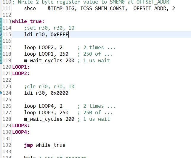
I rebuilt the PRU project, then the R5F project, and started a debug session for both. The program runs fine, and I can see the value for R30 change, but GPO10 on the physical board stays hovered around 0 V. I tried to write this loop to output a 1kHz square wave. I confirmed my scope probe on the 1kHz output on front of the scope, so I don't think it's an instrumentation issue.

Leaving both the R5F program and PRU on breakpoints, I poked around these registers to see if anything looked off. The AM6442 datasheet says signal PRG0_PRU0_GPO10 is MUX MODE 0 for Ball AA5/PADCONFIG98, which I have shown here:

And the GPCFG0 register should have MUX SEL 0, shown here (register viewed from the R5F perspective):

Assumption 4: For a PRU GPO signal to be routed out of the AM64x, proper muxing is need on both the SoC-wide PADCFG and the ICSSG_CFG.

So... what am I missing? Am I looking at the wrong registers?

Thanks in advance for reading this, I really appreciate it!
  • Hi Tim,

    Thank you for the detailed information on the steps you have followed.

    Assumption 0: After changing from some memory mappings, code written for the AM243x can also run on the R5F and PRU cores as they are basically the same.

    I believe you mean the code for AM243x can be used for AM64x as well and that is correct right.

    I would also like to add, we have dedicated ADC interfacing examples in our MCU+ SDK as well. You can evaluate them for your final use case of ADC interfacing. Refer EXAMPLES_PRU_ADC

    Assumption 3: In this dual-CCS-project example, a copy of the built PRU binary is stored as "pru0_load_bin.h" in a folder that the R5F project has access to, so the built R5F binary has the PRU binary baked into it, which the R5F drivers load into the PRU at runtime.

    That is correct, once the PRU project build completes the firmware header file pru_load_bin.h is copied to the /examples/pru_io/empty/firmware/{device}/ directory which is present in R5F project include options by default.

    Instructions in Firmware header file are written into the PRU IRAM memory using PRUICSS_loadFirmware API call in the R5F code.

    Assumption 4: For a PRU GPO signal to be routed out of the AM64x, proper muxing is need on both the SoC-wide PADCFG and the ICSSG_CFG.

    Regarding the Pinmux settings, you do not need to set anything manually. Once you select the required PRU pin in sysconfig, the pinmux settings are automatically handled.


    Now, regarding what could be the issue here,

    I have an oscilloscope measuring across pins 47 (DGND) and 53 (PRG0_PRU0GPO10) on the PRU connector (J10).

    From the schematics, it seems you are using the wrong pin for PRU0GPO10 signal. Can you try the pin shown below and let me know if that helps?

    Regards,

    Nitika

  • Hi Nitika,

    Thank you very much for the excellent answer. 

    TO FUTURE USERS: CHECK THE TITLE BLOCK ON YOUR SCHEMATIC. PROC100 and PROC100A have different PRU pinouts.
    Compare to the sticker on the SK-AM64x. My original boards were GP boards, which say PROC100E3 for Proc100, Rev E3. The SK-AM64B I have been working with is PROC100A. 

    I have been using a different schematic, seen below.

    Trying Pin 23 as you suggested works, thank you very much!

    Best,
    Tim Krentz