This thread has been locked.

If you have a related question, please click the "Ask a related question" button in the top right corner. The newly created question will be automatically linked to this question.

[FAQ] AM6442( AM64X) : How to Toggle GPIO Pin on PRU?

Part Number: AM6442
Other Parts Discussed in Thread: SYSCONFIG

Sitara devices have PRU cores that can execute instructions in a fully deterministic manner.

Therefore, users can use PRU cores for real-time I/O control applications.

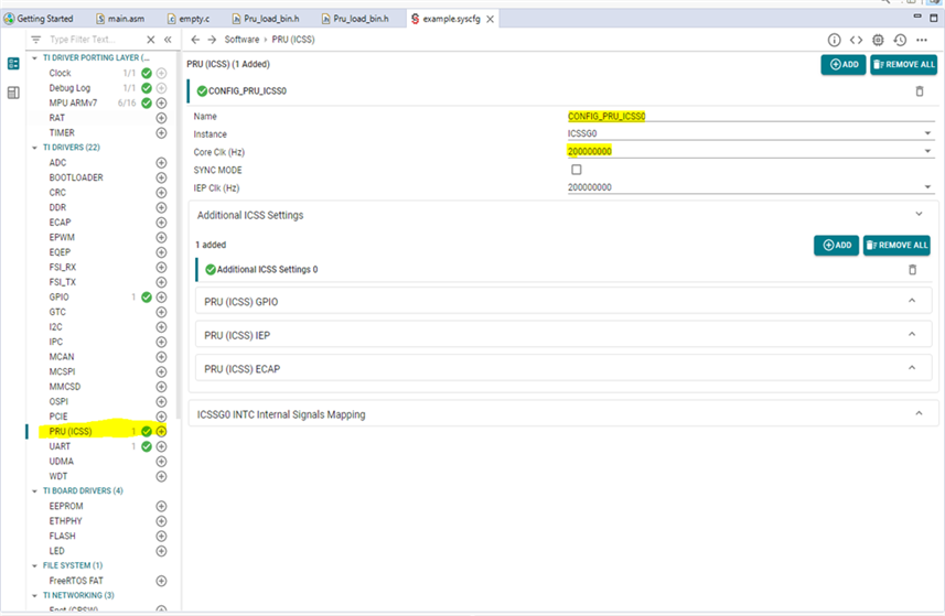
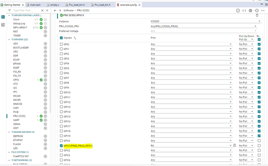
This FAQ is intended to explain how to write simple GPIO toggling software on PRU and how to load and run it from CCS.

  • AM64X: How to Toggle GPIO Pin on PRU?

    AM64X has two PRU cores. By default, PRU0 and PRU1 cores are able to control the all GPIO pins. Each PRU core is directly connected to 20 GPIO pins which can be controlled using R30 and R31 registers.

    Pin values can be read using R31 register.

    Pin values can be write using R30 register.

    Please use the link below for more details about PRU core.

    https://software-dl.ti.com/mcu-plus-sdk/esd/AM64X/latest/exports/docs/api_guide_am64x/PRU_IO.html

    PRU CPU Frequency and Pin Muxing is required to drive GPIO pins, for that we can include its code in main.asm file or easy way to do it is by using sysconfig available in MCU+SDK examples.

    Please follow the steps below in any example on R5F0_0. I chose the example below C:\ti\mcu_plus_sdk_am64x_08_05_00_24\examples\empty\am64x-evm\r5fss0-0_freertos.

    R5F0_0:

    1. Enable PRU Peripheral and select PRU CPU Clock Frequency in System Config. The various clock speed options available are 200MHz, 225MHz, 250MHz, 300MHz and 333MHz. Select your desired frequency.

    2. Select which GPIO pin you want to toggle from 20Pins. I selected GPO1 in my example.


    3. Compile your R5F0_0 Application.


    Please follow the steps below in an example on PRU_0. I chose the example below C:\ti\mcu_plus_sdk_am64x_08_05_00_24\examples\pru_io\empty\firmware\am64x-evm\icssg0-pru0_fw

    PRU_0:

    1. As mentioned above, we need the R30 register to control the output pins. I used the two instructions below to write logic high and low on a pin without any delay and execute the same instructions forever.

    main:
    
    init:
    
    	zero	&r0, 120
    
    ; Configure the Constant Table entry C28 to point to start of shared memory
    ; PRU_ICSSG Shared RAM (local-C28) : 00nn_nn00h, nnnn = c28_pointer[15:0]
    ;	ldi     R5, 0x0100
    ;    sbco    &R5, C11, 0x28, 2
    
    CHECK_FOR_SIGNAL:
    
            LDI                R30, 0x2 ; toggles GPIO pin 1
            LDI                R30, 0x0
            QBA                CHECK_FOR_SIGNAL ; Branch operation
    
        HALT


    For more details about the PRU Complete instruction set, please refer the link below.

    https://www.ti.com/lit/ug/spruij2/spruij2.pdf

    2.  Compile your PRU_0 Application.


    Load and Run PRU Application from CCS :

    1. Build the R5F project, launch the target configuration, connect to Cortex_R5_0_0 core
    2. Reset the core, load the built example by selecting Run -> Load -> Load Program.
    3. Select Browse Project. Select the .out file from the Debug folder and resume the core.
    4. Next, right click on the DMSC core and select Connect Target.
    5. Connect to the appropriate PRU core (e.g., PRU_0) and load the built example.
    6. The PRU firmware has been loaded into the PRU!

     Note:  if you want to load the PRU binaries in external memory, please use the FAQ below .

    https://e2e.ti.com/support/processors-group/processors/f/processors-forum/1183897/faq-am64x-how-to-load-flash-pru-binaries-into-external-memory

  • Example Projects : 

    I have attached example projects of R5F and PRU for your reference .

    R5F Project : 

    8688.empty_am64x-evm_r5fss0-0_freertos_ti-arm-clang.zip

    PRU Project : 

    0407.empty_am64x-evm_icssg0-pru0_fw_ti-pru-cgt.zip