This thread has been locked.

If you have a related question, please click the "Ask a related question" button in the top right corner. The newly created question will be automatically linked to this question.

PROCESSOR-SDK-J721E: setting date and time issue

Part Number: PROCESSOR-SDK-J721E


Tool/software:

Hi,

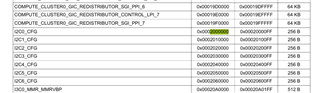
    I cannot set the date and time in J721E EVM common board after power cycle. When I set the date and time in EVM board, it will set at first. But when power cycle occur, the date and time will be the previous one, with a coin battery present in the holder. Along with this I cannot use hwclock -w command. 

Regards,

Rejin

  • Hello Rejin,

    What's the real time clock that you have enabled which ticks with coin cell battery? Also what does the coin battery power? The SoC will be reset. 

    Best Regards,

    Keerthy 

  • Hi Keerthy,

    I didn't enable any realtime clock. My battery is 3v. Battery type CR1220.

    Regards,

    Rejin

  • So the SoC is off and it won't be powered by a coin battery. It's usually fed with 12V. Then you can't expect it to tick.

    The EVM has an on board RTC. That needs to be enabled. What's the end use case? 

    Best Regards,

    Keerthy 

  • Hi Keerthy,

    I used the coin battery for maintaining the clock time when main power ie 12v is not given to the EVM board. The EVM board is completely powered with 12V supply. If board power is given then the time tick is fine. I don't know about the statement given above "The EVM has an on board RTC". I thing that on board RTC will work only when the 12V supply is present.

    Regards,

    Rejin

  • Hello Rejin,

    https://e2e.ti.com/support/processors/f/791/t/959163

    The Above FAQ is on an older SDK. By default the on EVM RTC is not enabled in the SDK. You can refer the above FAQ and make sure the RTC works.
    What gets fed with your coin battery?

    - Keerthy

  • Hi Keerthy,

    I followed the steps but it halted while "make linux" execution time. Attaching a screenshot

    Regards,

    Rejin

  • Hi,

    You need to do 'make linux' from the SDK installation folder.

    - Keerthy

  • Hi,

    I did command make linux

    Regards,

    Rejin

  • Rejin,

    cd ../..

    Basically you need to go 2 levels above and then:

    'make linux'

    - Keerthy

  • Hi Keerthy,

    I followed the steps and executed the 'make linux' command. It successfully created the Image and I copied image and .dtb file specified in the FAQ. But still time is not stable. When I reboot the board, time changed. I didn't power off the board.

    Regards,

    Rejin

  • Rejin,

    Can you make sure that the RTC is running across power off?

    Best Regards,

    Keerthy 

  • Hi Keerthy,

    RTC is not running after poweroff.

    Regards,

    Rejin

  • Hi Rejin,

    I am looping in the hardware expert to check how the coin cell battery needs to be connected and which RTC is powered up.

    Best Regards,

    Keerthy 

  • The EVM does NOT include the back-up battery for RTC functions.  This is required to maintain clock when EVM is off (unpowered).  Did you add correct battery?

  • Hi Robert,

    I added the same part no battery (CR1220).

    Regards,

    Rejin

  • The battery should be between 1.3V and 5.5v.  Do you have mechanism (voltmeter) to confirm battery is charged?

    I think the battery has to be enabled within the RTC device.  

    I believe the oscillator also has to be running.

  • Hi Robert,

    How could I enable this VBATEN bit in linuxOS and also where this document I can download. I measured the battery voltage across the battery holder terminal and I can read value as 3.17. 

    Regards,

    Rejin

  • The VBATEN bit is defined in the data sheet for the RTC controller.  It is NOT a Texas Instruments product, so just do search for MCP79410 for its documentation.  Re-assigning to help with linuxOS question.

  • Rejin,

    Do you know which i2c and whats the slave id? You can use i2cdump tool to read and i2cset tool to write to that register field.

    www.google.com/url

    Best regards,

    Keerthy 

  • Hi Keerthy,

    Here I am attaching some screenshots.

    Here I am using bus 3 for i2c0 Main specified in the schematic.

    Schematic from common processor board schematic. So i2c0 Main we are using and address can be 0x57 or 0x6F.

    i2cdump command I used for getting the register value for both the address. In that I thing our device address is 0x6F. After checking the register address 0x03 of RTC IC we can see that 3rd bit already high. So the input voltage is enabled already. Pardon me If I am wrong.

    Regards,

    Rejin

  • Hi Keerthy,

    I changed SD card OS to latest SDK(10.01)OS. Now I can change the time and I can use hwclock -w command. When I reboot the board it shows the same time when I executed the reboot command. When I poweroff the system for 2 hours and start the system, it will show the same time when I execute the poweroff command.

    Regards,

    Rejin

  • Okay. Thanks. Yes this is already set as per register description.

    Any other settings that need to be turned on for Coin cell powering up RTC?

    - Keerthy

  • Hi Keerthy,

    Yesterday and today I took values from registers of MCP79410 using i2cdump command and found that RTC is working fine. I think there is a sync missing between OS and RTC. After setting date and time in OS, it will work fine till power off. After power on, it will show the same date and time when power off command is given. OS didn't take the updated value from RTC.

    Regards,

    Rejin

  • Rejin,

    Thanks for the updates. So RTC is correctly powered up by Battery & works as expected.

    This is a core Linux phenomenon. There is some help online:
    https://unix.stackexchange.com/questions/285674/rtc-and-system-clock-not-in-sync

    Since I do not have the coin cell connected, I do not have a way to verify.

    - Keerthy

  • Hi keerthy,

    Above sync command also not working.

    Still RTC time is different from system time. I think hwclock -w is not working. Only we can set the time of OS. No other things we can't do.

    Regards,

    Rejin

  • Hi Rejin,

    This is best checked with linux-rtc linux mailing list. Since the RTC is now ticking as expected.

    - Keerthy

  • Hi Keerthy,

    When coin battery is inserted RTC starts ticking. But there is a missing in taking the RTC value to OS. That's why sync is not working. In some way there is a method to sync the RTC with OS in OS.

    Regards,

    Rejin

  • Hi Keerthy,

    I went through that document.

    RTC time shown is different from the value shown in i2cdump.

    I am attaching boot log here.

    Regards,

    Rejin

  • Rejin,

    So I see 2 RTCs:

    The Above FAQ is on an older SDK. By default the on EVM RTC is not enabled in the SDK. You can refer the above FAQ and make sure the RTC works.

    1) The above is the on board RTC.

    2) There is another RTC aka PMIC RTC. That is being used as the time source and hence you are seeing a delta.

    Can you disable the PMIC RTC node?

    diff --git a/arch/arm64/boot/dts/ti/k3-j721e-som-p0.dtsi b/arch/arm64/boot/dts/ti/k3-j721e-som-p0.dtsi
    index c0ade7a56..9830c7fe1 100644
    --- a/arch/arm64/boot/dts/ti/k3-j721e-som-p0.dtsi
    +++ b/arch/arm64/boot/dts/ti/k3-j721e-som-p0.dtsi
    @@ -216,6 +216,7 @@
            };
     
            tps659413: pmic@48 {
    +               status = "disabled";
                    compatible = "ti,tps6594-q1";
                    reg = <0x48>;
                    system-power-controller;
    @@ -304,6 +305,7 @@
            };
     
            tps659411: pmic@4c {
    +               status = "disabled";
                    compatible = "ti,tps6594-q1";
                    reg = <0x4c>;
                    system-power-controller;
    

    See if we can now make the On board RTC time aligned with system time.

    - Keerthy

  • Hi Keerthy,

    Can you please provide a solution for SDK 8.06.01. Because I found a lot of problem in sdk10.01. SDK08.06.01 is some what fine. 

    Regards,

    Rejin

  • Rejin,

    Could you double check if 8.6 had 2 RTCs under the /system/class/rtc?

    If there's single RTC then it must be the one you added. That should be easier to than 10.x. The tps RTC support was added after 8.6. please double check. 

    Best regards,

    Keerthy 

  • Hi keerthy,

    I checked the folder /sys/class/rtc/ in SD card which has created with 8.06 SDK and found no files or folders.

    Here I am attaching the file k3-j721e-som-p0.dtsi in code form taken from SDK8.06

    // SPDX-License-Identifier: GPL-2.0
    /*
     * Copyright (C) 2019-2020 Texas Instruments Incorporated - https://www.ti.com/
     */
    
    /dts-v1/;
    
    #include "k3-j721e.dtsi"
    
    / {
    	memory@80000000 {
    		device_type = "memory";
    		/* 4G RAM */
    		reg = <0x00000000 0x80000000 0x00000000 0x80000000>,
    		      <0x00000008 0x80000000 0x00000000 0x80000000>;
    	};
    
    	reserved_memory: reserved-memory {
    		#address-cells = <2>;
    		#size-cells = <2>;
    		ranges;
    
    		secure_ddr: optee@9e800000 {
    			reg = <0x00 0x9e800000 0x00 0x01800000>;
    			alignment = <0x1000>;
    			no-map;
    		};
    
    		mcu_r5fss0_core0_dma_memory_region: r5f-dma-memory@a0000000 {
    			compatible = "shared-dma-pool";
    			reg = <0x00 0xa0000000 0x00 0x100000>;
    			no-map;
    		};
    
    		mcu_r5fss0_core0_memory_region: r5f-memory@a0100000 {
    			compatible = "shared-dma-pool";
    			reg = <0x00 0xa0100000 0x00 0xf00000>;
    			no-map;
    		};
    
    		mcu_r5fss0_core1_dma_memory_region: r5f-dma-memory@a1000000 {
    			compatible = "shared-dma-pool";
    			reg = <0x00 0xa1000000 0x00 0x100000>;
    			no-map;
    		};
    
    		mcu_r5fss0_core1_memory_region: r5f-memory@a1100000 {
    			compatible = "shared-dma-pool";
    			reg = <0x00 0xa1100000 0x00 0xf00000>;
    			no-map;
    		};
    
    		main_r5fss0_core0_dma_memory_region: r5f-dma-memory@a2000000 {
    			compatible = "shared-dma-pool";
    			reg = <0x00 0xa2000000 0x00 0x100000>;
    			no-map;
    		};
    
    		main_r5fss0_core0_memory_region: r5f-memory@a2100000 {
    			compatible = "shared-dma-pool";
    			reg = <0x00 0xa2100000 0x00 0xf00000>;
    			no-map;
    		};
    
    		main_r5fss0_core1_dma_memory_region: r5f-dma-memory@a3000000 {
    			compatible = "shared-dma-pool";
    			reg = <0x00 0xa3000000 0x00 0x100000>;
    			no-map;
    		};
    
    		main_r5fss0_core1_memory_region: r5f-memory@a3100000 {
    			compatible = "shared-dma-pool";
    			reg = <0x00 0xa3100000 0x00 0xf00000>;
    			no-map;
    		};
    
    		main_r5fss1_core0_dma_memory_region: r5f-dma-memory@a4000000 {
    			compatible = "shared-dma-pool";
    			reg = <0x00 0xa4000000 0x00 0x100000>;
    			no-map;
    		};
    
    		main_r5fss1_core0_memory_region: r5f-memory@a4100000 {
    			compatible = "shared-dma-pool";
    			reg = <0x00 0xa4100000 0x00 0xf00000>;
    			no-map;
    		};
    
    		main_r5fss1_core1_dma_memory_region: r5f-dma-memory@a5000000 {
    			compatible = "shared-dma-pool";
    			reg = <0x00 0xa5000000 0x00 0x100000>;
    			no-map;
    		};
    
    		main_r5fss1_core1_memory_region: r5f-memory@a5100000 {
    			compatible = "shared-dma-pool";
    			reg = <0x00 0xa5100000 0x00 0xf00000>;
    			no-map;
    		};
    
    		c66_1_dma_memory_region: c66-dma-memory@a6000000 {
    			compatible = "shared-dma-pool";
    			reg = <0x00 0xa6000000 0x00 0x100000>;
    			no-map;
    		};
    
    		c66_0_memory_region: c66-memory@a6100000 {
    			compatible = "shared-dma-pool";
    			reg = <0x00 0xa6100000 0x00 0xf00000>;
    			no-map;
    		};
    
    		c66_0_dma_memory_region: c66-dma-memory@a7000000 {
    			compatible = "shared-dma-pool";
    			reg = <0x00 0xa7000000 0x00 0x100000>;
    			no-map;
    		};
    
    		c66_1_memory_region: c66-memory@a7100000 {
    			compatible = "shared-dma-pool";
    			reg = <0x00 0xa7100000 0x00 0xf00000>;
    			no-map;
    		};
    
    		c71_0_dma_memory_region: c71-dma-memory@a8000000 {
    			compatible = "shared-dma-pool";
    			reg = <0x00 0xa8000000 0x00 0x100000>;
    			no-map;
    		};
    
    		c71_0_memory_region: c71-memory@a8100000 {
    			compatible = "shared-dma-pool";
    			reg = <0x00 0xa8100000 0x00 0xf00000>;
    			no-map;
    		};
    
    		rtos_ipc_memory_region: ipc-memories@aa000000 {
    			reg = <0x00 0xaa000000 0x00 0x01c00000>;
    			alignment = <0x1000>;
    			no-map;
    		};
    
    		main_r5fss0_core0_shared_memory_queue_region:r5f-virtual-eth-queues@ac000000 {
    			compatible = "shared-dma-pool";
    			reg = <0x00 0xac000000 0x00 0x200000>;
    			no-map;
    		};
    
    		main_r5fss0_core0_shared_memory_bufpool_region:r5f-virtual-eth-buffers@ac200000 {
    			compatible = "shared-dma-pool";
    			reg = <0x00 0xac200000 0x00 0x1e00000>;
    			no-map;
    		};
    	};
    };
    
    &wkup_pmx0 {
    	wkup_i2c0_pins_default: wkup-i2c0-pins-default {
    		pinctrl-single,pins = <
    			J721E_WKUP_IOPAD(0xf8, PIN_INPUT_PULLUP, 0) /* (J25) WKUP_I2C0_SCL */
    			J721E_WKUP_IOPAD(0xfc, PIN_INPUT_PULLUP, 0) /* (H24) WKUP_I2C0_SDA */
    		>;
    	};
    
    	mcu_fss0_ospi0_pins_default: mcu-fss0-ospi0-pins-default {
    		pinctrl-single,pins = <
    			J721E_WKUP_IOPAD(0x0000, PIN_OUTPUT, 0) /* MCU_OSPI0_CLK */
    			J721E_WKUP_IOPAD(0x0008, PIN_INPUT, 0)  /* MCU_OSPI0_DQS */
    			J721E_WKUP_IOPAD(0x000c, PIN_INPUT, 0)  /* MCU_OSPI0_D0 */
    			J721E_WKUP_IOPAD(0x0010, PIN_INPUT, 0)  /* MCU_OSPI0_D1 */
    			J721E_WKUP_IOPAD(0x0014, PIN_INPUT, 0)  /* MCU_OSPI0_D2 */
    			J721E_WKUP_IOPAD(0x0018, PIN_INPUT, 0)  /* MCU_OSPI0_D3 */
    			J721E_WKUP_IOPAD(0x001c, PIN_INPUT, 0)  /* MCU_OSPI0_D4 */
    			J721E_WKUP_IOPAD(0x0020, PIN_INPUT, 0)  /* MCU_OSPI0_D5 */
    			J721E_WKUP_IOPAD(0x0024, PIN_INPUT, 0)  /* MCU_OSPI0_D6 */
    			J721E_WKUP_IOPAD(0x0028, PIN_INPUT, 0)  /* MCU_OSPI0_D7 */
    			J721E_WKUP_IOPAD(0x002c, PIN_OUTPUT, 0) /* MCU_OSPI0_CSn0 */
    		>;
    	};
    };
    
    &ospi0 {
    	pinctrl-names = "default";
    	pinctrl-0 = <&mcu_fss0_ospi0_pins_default>;
    
    	flash@0{
    		compatible = "jedec,spi-nor";
    		reg = <0x0>;
    		spi-tx-bus-width = <8>;
    		spi-rx-bus-width = <8>;
    		spi-max-frequency = <25000000>;
    		cdns,tshsl-ns = <60>;
    		cdns,tsd2d-ns = <60>;
    		cdns,tchsh-ns = <60>;
    		cdns,tslch-ns = <60>;
    		cdns,read-delay = <0>;
    		#address-cells = <1>;
    		#size-cells = <1>;
    
    		partitions {
    			compatible = "fixed-partitions";
    			#address-cells = <1>;
    			#size-cells = <1>;
    
    			partition@0 {
    				label = "ospi.tiboot3";
    				reg = <0x0 0x80000>;
    			};
    
    			partition@80000 {
    				label = "ospi.tispl";
    				reg = <0x80000 0x200000>;
    			};
    
    			partition@280000 {
    				label = "ospi.u-boot";
    				reg = <0x280000 0x400000>;
    			};
    
    			partition@680000 {
    				label = "ospi.env";
    				reg = <0x680000 0x20000>;
    			};
    
    			partition@6a0000 {
    				label = "ospi.env.backup";
    				reg = <0x6a0000 0x20000>;
    			};
    
    			partition@6c0000 {
    				label = "ospi.sysfw";
    				reg = <0x6c0000 0x100000>;
    			};
    
    			partition@800000 {
    				label = "ospi.rootfs";
    				reg = <0x800000 0x37c0000>;
    			};
    
    			partition@3fe0000 {
    				label = "ospi.phypattern";
    				reg = <0x3fe0000 0x20000>;
    			};
    		};
    	};
    };
    
    &mailbox0_cluster0 {
    	interrupts = <436>;
    
    	mbox_mcu_r5fss0_core0: mbox-mcu-r5fss0-core0 {
    		ti,mbox-rx = <0 0 0>;
    		ti,mbox-tx = <1 0 0>;
    	};
    
    	mbox_mcu_r5fss0_core1: mbox-mcu-r5fss0-core1 {
    		ti,mbox-rx = <2 0 0>;
    		ti,mbox-tx = <3 0 0>;
    	};
    };
    
    &mailbox0_cluster1 {
    	interrupts = <432>;
    
    	mbox_main_r5fss0_core0: mbox-main-r5fss0-core0 {
    		ti,mbox-rx = <0 0 0>;
    		ti,mbox-tx = <1 0 0>;
    	};
    
    	mbox_main_r5fss0_core1: mbox-main-r5fss0-core1 {
    		ti,mbox-rx = <2 0 0>;
    		ti,mbox-tx = <3 0 0>;
    	};
    };
    
    &mailbox0_cluster2 {
    	interrupts = <428>;
    
    	mbox_main_r5fss1_core0: mbox-main-r5fss1-core0 {
    		ti,mbox-rx = <0 0 0>;
    		ti,mbox-tx = <1 0 0>;
    	};
    
    	mbox_main_r5fss1_core1: mbox-main-r5fss1-core1 {
    		ti,mbox-rx = <2 0 0>;
    		ti,mbox-tx = <3 0 0>;
    	};
    };
    
    &mailbox0_cluster3 {
    	interrupts = <424>;
    
    	mbox_c66_0: mbox-c66-0 {
    		ti,mbox-rx = <0 0 0>;
    		ti,mbox-tx = <1 0 0>;
    	};
    
    	mbox_c66_1: mbox-c66-1 {
    		ti,mbox-rx = <2 0 0>;
    		ti,mbox-tx = <3 0 0>;
    	};
    };
    
    &mailbox0_cluster4 {
    	interrupts = <420>;
    
    	mbox_c71_0: mbox-c71-0 {
    		ti,mbox-rx = <0 0 0>;
    		ti,mbox-tx = <1 0 0>;
    	};
    };
    
    &mailbox0_cluster5 {
    	status = "disabled";
    };
    
    &mailbox0_cluster6 {
    	status = "disabled";
    };
    
    &mailbox0_cluster7 {
    	status = "disabled";
    };
    
    &mailbox0_cluster8 {
    	status = "disabled";
    };
    
    &mailbox0_cluster9 {
    	status = "disabled";
    };
    
    &mailbox0_cluster10 {
    	status = "disabled";
    };
    
    &mailbox0_cluster11 {
    	status = "disabled";
    };
    
    &mcu_r5fss0_core0 {
    	mboxes = <&mailbox0_cluster0 &mbox_mcu_r5fss0_core0>;
    	memory-region = <&mcu_r5fss0_core0_dma_memory_region>,
    			<&mcu_r5fss0_core0_memory_region>;
    };
    
    &mcu_r5fss0_core1 {
    	mboxes = <&mailbox0_cluster0 &mbox_mcu_r5fss0_core1>;
    	memory-region = <&mcu_r5fss0_core1_dma_memory_region>,
    			<&mcu_r5fss0_core1_memory_region>;
    };
    
    &main_r5fss0_core0 {
    	mboxes = <&mailbox0_cluster1 &mbox_main_r5fss0_core0>;
    	memory-region = <&main_r5fss0_core0_dma_memory_region>,
    			<&main_r5fss0_core0_memory_region>,
    			<&main_r5fss0_core0_shared_memory_queue_region>,
    			<&main_r5fss0_core0_shared_memory_bufpool_region>;
    };
    
    &main_r5fss0_core1 {
    	mboxes = <&mailbox0_cluster1 &mbox_main_r5fss0_core1>;
    	memory-region = <&main_r5fss0_core1_dma_memory_region>,
    			<&main_r5fss0_core1_memory_region>;
    };
    
    &main_r5fss1_core0 {
    	mboxes = <&mailbox0_cluster2 &mbox_main_r5fss1_core0>;
    	memory-region = <&main_r5fss1_core0_dma_memory_region>,
    			<&main_r5fss1_core0_memory_region>;
    };
    
    &main_r5fss1_core1 {
    	mboxes = <&mailbox0_cluster2 &mbox_main_r5fss1_core1>;
    	memory-region = <&main_r5fss1_core1_dma_memory_region>,
    			<&main_r5fss1_core1_memory_region>;
    };
    
    &c66_0 {
    	mboxes = <&mailbox0_cluster3 &mbox_c66_0>;
    	memory-region = <&c66_0_dma_memory_region>,
    			<&c66_0_memory_region>;
    };
    
    &c66_1 {
    	mboxes = <&mailbox0_cluster3 &mbox_c66_1>;
    	memory-region = <&c66_1_dma_memory_region>,
    			<&c66_1_memory_region>;
    };
    
    &c71_0 {
    	mboxes = <&mailbox0_cluster4 &mbox_c71_0>;
    	memory-region = <&c71_0_dma_memory_region>,
    			<&c71_0_memory_region>;
    };

    Regards,

    Rejin

  • Then please add the RTC node for the on board RTC. That should get the time sync.

    10.x SDK will have tps RTC. So 8.6 should be easier.

    Best regards,

    Keerthy 

  • Hi Keerthy,

    By adding the code below in the above mentioned file is enough to add an RTC or some where else we need to modify.

    diff --git a/arch/arm64/boot/dts/ti/k3-j721e-som-p0.dtsi b/arch/arm64/boot/dts/ti/k3-j721e-som-p0.dtsi
    index c0ade7a56..9830c7fe1 100644
    --- a/arch/arm64/boot/dts/ti/k3-j721e-som-p0.dtsi
    +++ b/arch/arm64/boot/dts/ti/k3-j721e-som-p0.dtsi
    @@ -216,6 +216,7 @@
            };
     
            tps659413: pmic@48 {
    +               status = "disabled";
                    compatible = "ti,tps6594-q1";
                    reg = <0x48>;
                    system-power-controller;
    @@ -304,6 +305,7 @@
            };
     
            tps659411: pmic@4c {
    +               status = "disabled";
                    compatible = "ti,tps6594-q1";
                    reg = <0x4c>;
                    system-power-controller;

    Regards,

    Rejin

  • Rejin,

    The above was to disable the PMIC RTC in the latest 10.0 SDK. I believe you are asking for 8.6 SDK. Check if the tps* nodes are present if not then in 8.6 there will be no PMIC RTC.

    The other thing would be to enable the on board RTC as per 

    e2e.ti.com/.../quote]

    Then we are sure only the on board RTC is the time source. Hope I am clear?

    - Keerthy

  • Hi Keerthy,

    Now I have another issue. my RTC suddenly stopped working. Now it is not ticking.

    I am attaching another screenshot

    Here we can see that 0x03 register has vale 1c but it should show as 3c. OSCRUN bit is low.

    Its a read only bit. So through program we cannot change the value. What is the reason behind this problem.

    Regards,

    Rejin

  • This new issue is from the 8.6 SDK? How did you encounter this issue? 

    Best regards,

    Keerthy 

  • Hi Keerthy,

    After linux make and I boot the new sd card, I noticed that RTC not ticking. I inserted the latest SD card but still it is not working. What is the reason to stop the OSCRUN. I changed the sd card image with the default image present in the SDK 8.06.01 and checked. But no change from the previous state.

    Regards,

    Rejin

  • Rejin,

    When you initially had it working was it from the 10.1 SDK or 8.6? Can you verify that is working?

    Your dtb should have the RTC node that you must have added for the on board RTC.

    Can you make sure that the RTC driver is getting proved?

    Best regards,

    Keerthy 

  • Hi Keerthy,

    When we saw that RTC was working I was using SDK 10.01. I checked with latest sd card to run the RTC when I saw it is not working. But now no OS can turn the RTC on.

    How can I prove RTC driver is working or not. How can I verify my RTC node is added.

    Regards,

    Rejin 

  • Rejin,

    Since you had RTC functional on 10.0 could you please continue instead of debugging on older SDK?

    Just disable the PMIC RTC and try the above Linux commands to sync system time.

    Let me know. 

    Best regards,

    Keerthy 

  • Rejin,

    Since you had RTC functional on 10.0 could you please continue instead of debugging on older SDK?

    Just disable the PMIC RTC and try the above Linux commands to sync system time.

    Let me know. 

    Best regards,

    Keerthy 

  • Hi Keerthy,

    I changed the content in the file linux/arch/arm64/boot/dts/ti/k3-j721e-som-p0.dtsi and executed make linux command. After I copied the Image from boot to sd card root/boot/ location. Then i boot the board from SD card and I found no differences from the previous one. Before the change in the file, I inspected the location /sys/class/rtc/ and found only one folder rtc0. After the file content changed, I found only the same file that exist previously.

    Please go through the below two screenshot.

    First image from latest SDK root/boot and the second one is from SDK 8.06. In SDK 8.06, Image is linked but in latest Image is not linked. I think the image I created is not linked properly.

    Regards,

    Rejin

  • Hello Rejin,

    Then i believe you had never enabled the in board RTC at the first place. You were always seeing the PMIC RTC. 

     Make sure that you copy both dtb and Linux and modules. 

    There's a command 

    make linux_install

    This should install the modules correctly. 

    Make sure that your rootfs path is set correctly to your sd card rootfs path in the file Rules.make in the top SDK folder. 

    Best regards,

    Keerthy 

  • Hi Keerthy,

    I did the above mentioned command after make linux command and now rtc0 is not present.

    Now I think PMIC RTC is disabled. What to do next.

    Regards,

    Rejin

  • You need to follow the FAQ and add the on board RTC device tree node. Compile using 'make linux' followed by copying dtb and modules via

    'make linux_install' command. 

    Best regards,

    Keerthy 

  • Hi Keerthy,

    Now its working. RTC now sync with OS.

    Thank you very much for the support.

    Regards,

    Rejin

  • Awesome! Glad it is functional now. For future references can you please share the patch?

    - Keerthy

  • Hi Keerthy,

    Pardon me for my Ignorance. I don't know how to create a patch. I will give the steps that I did to rectify the problem. Is it ok? I did the same thing that mentioned in the above FAQ and our conversation. I think patch is creating for the changes to apply in the files in the SDK.

    Regards,

    Rejin