This thread has been locked.

If you have a related question, please click the "Ask a related question" button in the top right corner. The newly created question will be automatically linked to this question.

PROCESSOR-SDK-AM62X: AM62RM interrupt sources not user understandable

Part Number: PROCESSOR-SDK-AM62X

Tool/software:

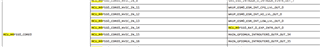
Table 10-11, the interrupt sources on column 2 really confusing users.

In this table, which IRQ number is mapped to system tick ?

What IRQ numbers on the above table are the NVIC IRQ 1-15 mapped to ?

I am expecting that interrupt sources should be meaningful like module (TIMER), event (overflow) combination, not just dump TI internal  doc keywords here as user manual

Thanks,

Jim 

  • Hello Jim,

    Thank you for the query.

    I am assigning the query to the expert.

    Regards,

    Sreenivasa

  • Jim

    The interrupt chapter has been updated an will be included in the next TRM release.  Below is a copy of the update.  

    --Paul

    AM62x_Interrupts (30Jan25-2).pdf

  • The new version is better than previous one; but still I can not find the info.

    Which IRQ number is the sys tick interrupt?

    Which IRQ number is the SVCALL ?

    Which IRQ number is the PendSVC ?

    There are 16 exceptions in Cortex M4, how are those exception mapped to those IRQ numbers ?

    Thanks,

  • Hi Paul: 

    are we trying to do same interrupt artifact for the AM64x in time for the SDK v12 release? Please also cc new marketing person (24) Kathryn Kalouf's Profile - Kathryn Kalouf - TI E2E support forums on your response.

    thanks

    Jim

  • any update on my questions 4 days ago?

  • Jim 

    I've looped in the software support as the TICK and SVCALL are software concepts.

    Just waiting on them providing input. 

    --Paul 

  • Hi Jim,

    Thanks for your patience.

    Which IRQ number is the sys tick interrupt?

    Which IRQ number is the SVCALL ?

    Which IRQ number is the PendSVC ?

    Interrupt number for SVC is 11, PendSV is 14 & Sys_tick is 15.

    There are 16 exceptions in Cortex M4, how are those exception mapped to those IRQ numbers ?

    Please refer {MCU+SDK}\source\kernel\freertos\dpl\m4\HwiP_armv7m_handlers_freertos.c file to see interrupt mapping.

    Regards,

    Tushar

  • I had used NXP cortex m4 for many years, and I knew the SVC is 11, PendSV is 14 & Sys_tick is 15, and the first 16 IRQ are mapped to first 16 IRQ numbers. I just want to confirm that TI is doing the same.

    Even from the new version (Jan 2025 version) of AM62 TRM, I cannot figure out those IRQ mapping you mentioned above.

    How can a user map MAIN_GPIOMUX_INTROUTER0_OUTP_OUT_34 with sys tick ?   The interrupt sources on the last column do not make any sense to users

    I got the interrupt source info confirmed, please close this issue. 

  • Tushar, Sreenivasa:

     I believe that "Jim Zhang" brings up a TI  competitor input to the Sitara team. It makes sense to have certain IRQ numbers of HwiP_armv7m_handlers_freertos.c into the TRM so that users that come from TI competitors' ARM solutions can easily migrate. Note that not everyone does not have to the original ARM m4 core documents (or r5 or A53 for that matter) that govern the IRQ assignments. 

    Please consider this for SDK 12 timeframes

    thanks

    Jim

  • I have the original ARM M4 doc, but this TRM does not map the interrupt to original ARM M4 core clearly; The interrupt sources in the TRM table made me confusing. I guess it uses term or keyword which only TI employee developers understand them

  • Jim

    The TRM lists the physical interrupt mappings on the devices.   There are two tables, one sorted by instance interrupt inputs, and one by instance interrupts outputs. 

    The TICK, SVC, and PendSVC are software terms that map to the physical instances/interrupts. 

    Can you provided examples of the mapping confusion? 

    --Paul 

  • what is the purpose of TRM ?  Is it for HW designer or software designer ?  For software developers, we need know how the interrupt source we use is mapping in the processor.  We need know the IRQ number for sys tick, we need know MCU_TIMER0 overflow interrupt IRQ number. We need be able to get those info from user manually.   

  • what is the purpose of TRM ?  Is it for HW designer or software designer ? 

    It's for both. 

    For software developers, we need know how the interrupt source we use is mapping in the processor.  We need know the IRQ number for sys tick, we need know MCU_TIMER0 overflow interrupt IRQ number. We need be able to get those info from user manually

    The mapping of the timer interrupts are listed in the document. For example 

    This shows that the interrupt from timer0 connects to the MCU_M4FS0, CORE0, NVIC input 4

    For the SYSTICK being Identified as the source for interrupt 15, as well as the others you asked about,  I will file a ticket to see if this can be document in the TRM. 

    Thank you for the valuable feedback. 

    --Paul 

  • Paul - please add same for AM64x come SDK v 11 timeframes; cc: k-kalouf@ti.com 

  • This is the confusing part of the TRM, from  {MCU+SDK}\source\kernel\freertos\dpl\m4\HwiP_armv7m_handlers_freertos.c, 0~15 should be mapped to cortex M4 core exceptions, can not be used as timer IRQ

    Here is the exception handlers in HwiP_armv7m_handlers_freertos.c, IRQ 4 is used by memFault excepion, can not be timer inerrupt

    uint32_t __attribute__((section(".vectors"), aligned(32))) gHwiP_vectorTable[HwiP_MAX_INTERRUPTS]  = {

        [0] = (uint32_t)&__STACK_END,             /* 0 */

        [1] = (uint32_t)&_c_int00,                /* 1 */

        [2] = (uint32_t)&HwiP_nmi_handler,        /* 2 */

        [3] = (uint32_t)&HwiP_hardFault_handler,  /* 3 */

        [4] = (uint32_t)&HwiP_memFault_handler,   /* 4 */

        [5] = (uint32_t)&HwiP_busFault_handler,   /* 5 */

        [6] = (uint32_t)&HwiP_usageFault_handler, /* 6 */

        [7] = (uint32_t)&HwiP_reserved_handler,   /* 7 */

        [8] = (uint32_t)&HwiP_reserved_handler,   /* 8 */

        [9] = (uint32_t)&HwiP_reserved_handler,   /* 9 */

        [10] = (uint32_t)&HwiP_reserved_handler,   /* 10 */

        [11] = (uint32_t)&vPortSVCHandler,         /* 11 */

        [12] = (uint32_t)&HwiP_debugMon_handler,   /* 12 */

        [13] = (uint32_t)&HwiP_reserved_handler,   /* 13 */

        [14] = (uint32_t)&xPortPendSVHandler,      /* 14 */

        [15] = (uint32_t)&HwiP_interrupt_handler,  /* 15 */ /* SysTick */

        /* rest of the handlers are setup in HwiP_init and would be for 

         * the 'external' NVIC interrupts

         */

    };

    TRM and code does not match. I think the TRM is not correct.

    My general feeling for TI document is:  TI does not build the actual house, the house is missing a lot of important parts, TI document writer assumes that user will find the right lego to complete the house. The problem is before everything works for the user, the user does not know if the lego he found is correct or not. The user has to spend a lot of time to verify if the lego he found is the correct one or not. That wastes new user tons of time.

  • JIm

    I've continued to look at this.  The exceptions listed in HwiP_armv7m_handlers_freertos.c are "built-in" CPU exceptions which are not documented in the TRM.  The TRM documents only the external peripheral interrupt sources and I believe that is where the confusion is happening. 

    We will see what we can do to make this clearer. 

    --Paul

  • I am glad that you will look into this, thank you. But the IRQ number should not be conflict between external IRQ and Cortex M4 core exceptions, please check

    Thanks

  • Jim

    While looking in to this, I've seen different representations of how the internal exceptions are presented.  The current vector numbers in the tables are aligned with the M4F external interrupt bus index so the solution may be a simple as offsetting the peripheral interrupt vectors by 16 to align with software. However, this may not be the correct answer, so I have filed an internal ticket to have it looked at so that it can be addressed in a future TRM release. 

    --Paul 

  • Could you find the answer and give me the answer here before next document release? I need correct IRQ interrupt number/source mapping in my code. Of course I cannot define 4 as the timer irq number. I need updated IRQ numbers for all the external IRQ sources listed in the TRM table

  • Paul:  it looks like Jim Z is asking for a TRM Errata. better cc :m-firth@ti.com 

  • Jim:

    Yes, I need answer or confirmation on the IRQ mapping. It may not be in any formal document, just an expert to tell me how to map the IRQ number on the TRM table to the IRQ number caught by Cortex M4 core when the source on the TRM table triggers the interrupt. I need the correct mapping for my project

    Thanks,

  • Paul:  it looks like Jim Z is asking for a TRM Errata. better cc :m-firth@ti.com 

    We only publish a silicon Errata. 

    Yes, I need answer or confirmation on the IRQ mapping. It may not be in any formal document, just an expert to tell me how to map the IRQ number on the TRM table to the IRQ number caught by Cortex M4 core when the source on the TRM table triggers the interrupt. I need the correct mapping for my project

    I'll have the software team comment on the mapping used. 

    --Paul

  • Hello Jim,

    Sorry for the above issues.

    To enable M4F core interrupts, you need to add the 16 value offset values to all the source interrupts.

    For example, you need to route WarmReset interrupt which is index value 9 to M4F Core.

    Then enable the interrupt for 16+9 = 25 number.

        HwiParams.intNum = 25;

    Another, you need to route Timer0 interrupt to M4F core.

    In this case Timer 0 interrupt index is 4 , you need to enable an interrupt for the 20th number.

        HwiParams.intNum = 20;

    For the GPIO interrupts, users  can't be enable directly  and these interrupt allocations are done through the SCI client because these outputs are Router outputs and shared between different cores.

    Except the Routers interrupts , you can simply add 16 offset values to all interrupts that are given in the TRM.

    Regards,

    Anil.

  • Anil:

    So PaulM assumption is right:

    The current vector numbers in the tables are aligned with the M4F external interrupt bus index so the solution may be a simple as offsetting the peripheral interrupt vectors by 16 to align with software.

    I will need add 16 offset on the IRQ number in the table to get the correct IRQ number captured by ARM core. Please confirm that, then this issue is solved.

    Thanks,

    Jim

  • Other than adding text into the TRM that an offset of 16 (decimal?) is needed - that should be easy to remedy.

  • Jim

    Yes, 16 decimal. 

    As mentioned earlier, a ticket has already been filed to update the TRM. 

    --Paul