This thread has been locked.

If you have a related question, please click the "Ask a related question" button in the top right corner. The newly created question will be automatically linked to this question.

AM625: MCASP1 Sync mode

Part Number: AM625
Other Parts Discussed in Thread: PCM5102A, PCM5102, , SYSCONFIG

Tool/software:

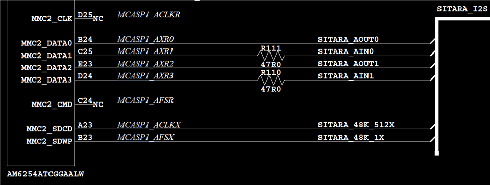
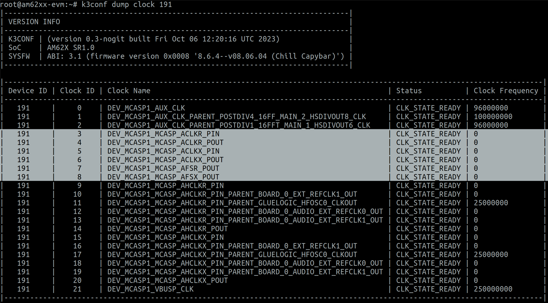
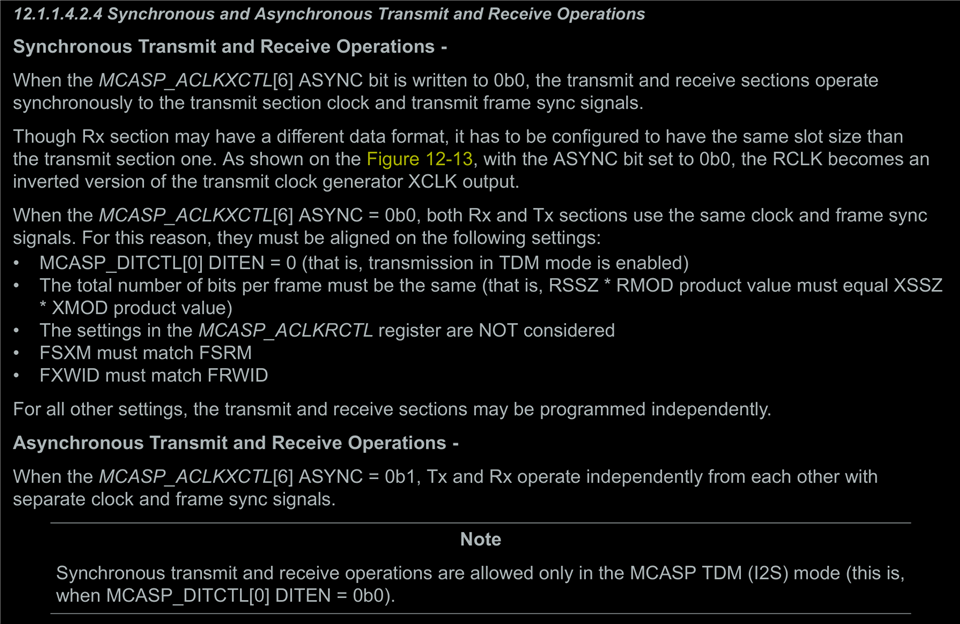
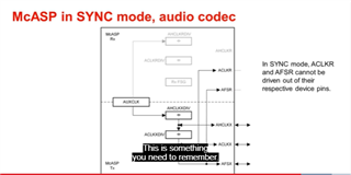
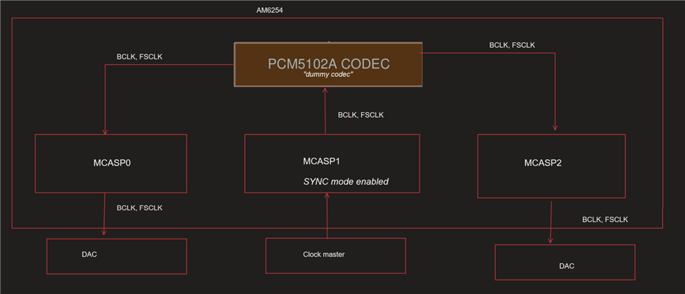
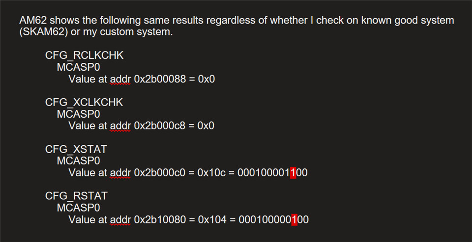
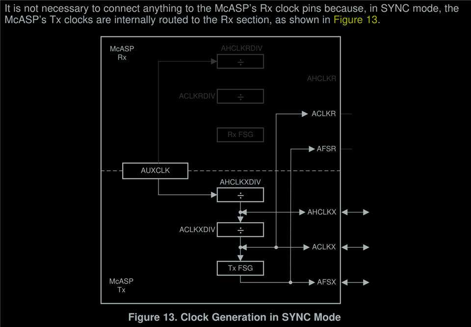
Main question: Is it possible to put AM6254 MCASP1 into Sync mode as described in section 4.3 (figure 13) of app note "SPRACK0 McASP Design Guide - Tips, Tricks, and Practical Examples"?

The app note says I can set this in ACLKXCTL, but looking at section 14.8.1.1.16.1 of TRM SPRUIV7B It's not clear if this is possible.

I'm using Linux TISDK v09.01.00.08.

  • Hi Dan,

    Apologies for the delayed response. I think you are looking at the wrong section 14.8.1.1.16.1. This section is about the CFG_ACLKRCTL not CFG_ACLKXCTL Register.
    Please check section 14.8.1.1.28 CFG_ACLKXCTL Registers. You can find the sync mode option in the 6th bit of it. 

    Regards,
    Ritapravo

  • I see, thank you.

    I'm trying to test this feature and it does not appear to function as expected.

    I'm routing 24.5MHz Bit clock and 48kHz FS clock to the pins shown below and I've verified that the signals are good on oscilloscope.

    Then I check the state of MCASP1 clock on the AM62:

    Question: With k3conf, shouldn't I be seeing the frequency for the clocks highlighted above?

    I verified that sync mode is set correctly:

  • Question: If I'm enabling sync mode, are there any additional settings required to support this mode?

    I'm reading clock errors after setting the mode.

    read CFG_XSTAT                                                      
        MCASP0                                                              
        Value at addr 0x2b000c0 = 0x10c                                     
        MCASP1                                                              
        Value at addr 0x2b100c0 = 0x10c                                     
        MCASP2                                                              
        Value at addr 0x2b200c0 = 0x10c                                     
    
    read CFG_RSTAT                                                      
        MCASP0                                                              
        Value at addr 0x2b10080 = 0x104 
        MCASP1                                                              
        Value at addr 0x2b10080 = 0x104 
        MCASP2                                                              
        Value at addr 0x2b10080 = 0x104

    I am trying to use this input clock as a clock master for MCASP0, MCASP1, and MCASP2.

    Taking MCASP1 as example, I do it with the following device tree code:

    	mcasp1: audio-controller@2b10000 {
    		compatible = "ti,am33xx-mcasp-audio";
    		reg = <0x00 0x02b10000 0x00 0x2000>,
    		      <0x00 0x02b18000 0x00 0x400>;
    		reg-names = "mpu","dat";
    		interrupts = <GIC_SPI 238 IRQ_TYPE_LEVEL_HIGH>,
    				<GIC_SPI 237 IRQ_TYPE_LEVEL_HIGH>;
    		interrupt-names = "tx", "rx";
    
    		dmas = <&main_bcdma 0 0xc501 0>, <&main_bcdma 0 0x4501 0>;
    		dma-names = "tx", "rx";
    
    		clocks = <&k3_clks 191 0>;
    		clock-names = "fck";
    		assigned-clocks = <&k3_clks 191 0>;
    		assigned-clock-parents = <&k3_clks 191 2>;
    		power-domains = <&k3_pds 191 TI_SCI_PD_EXCLUSIVE>;
    		status = "disabled";
    	};
    	
    		zynq_pcm5102a: pcm5102a@1 {
    		#sound-dai-cells = <0>;
    		compatible = "ti,pcm5102a";
    		status = "okay";
    	};
    
    	zynq_audio: sound@1 {
    		compatible = "simple-audio-card";
    		simple-audio-card,name = "TIZynq";
    		simple-audio-card,format = "dsp_b";
    		simple-audio-card,bitclock-master = <&zynq_audio_master>;
    		simple-audio-card,frame-master = <&zynq_audio_master>;
    		//simple-audio-card,bitclock-inversion;
    
    		simple-audio-card,cpu {
    			sound-dai = <&mcasp1>;
    			dai-tdm-slot-num = <16>;
    			dai-tdm-slot-width = <32>;
    		};
    
    		zynq_audio_master: simple-audio-card,codec {
    			#sound-dai-cells = <0>;
    			sound-dai = <&zynq_pcm5102a>;
    		};
    	};
    	
    		mcasp1_pins_default: mcasp1-pins-default {
    		pinctrl-single,pins = <
    			AM62X_IOPAD(0x0118, PIN_INPUT, 1) /* (D25) MMC2_CLK.MCASP1_ACLKR */
    			AM62X_IOPAD(0x0124, PIN_INPUT, 1) /* (A23) MMC2_SDCD.MCASP1_ACLKX */
    			AM62X_IOPAD(0x0120, PIN_INPUT, 1) /* (C24) MMC2_CMD.MCASP1_AFSR */
    			AM62X_IOPAD(0x0128, PIN_INPUT, 1) /* (B23) MMC2_SDWP.MCASP1_AFSX */
    			AM62X_IOPAD(0x0114, PIN_OUTPUT, 1) /* (B24) MMC2_DAT0.MCASP1_AXR0 */
    			AM62X_IOPAD(0x0110, PIN_INPUT, 1) /* (C25) MMC2_DAT1.MCASP1_AXR1 */
    			AM62X_IOPAD(0x010c, PIN_OUTPUT, 1) /* (E23) MMC2_DAT2.MCASP1_AXR2 */
    			AM62X_IOPAD(0x0108, PIN_INPUT, 1) /* (D24) MMC2_DAT3.MCASP1_AXR3 */
    		>;
    	};
    
    
    &mcasp1 {
    	status = "okay";
    	#sound-dai-cells = <0>;
    
    	pinctrl-names = "default";
    	pinctrl-0 = <&mcasp1_pins_default>;
    
    	op-mode = <0>;          /* 0 = MCASP_IIS_MODE or MCASP_TDM_MODE*/
    	tdm-slots = <16>; 		/* TDM slots used */
        tdm-slot-width = <32>;   /* 32-bit per channel */
    
    	/* McASP1 has 6 available serializers */
    	num-serializer = <6>;
        serial-dir = <
            1 2 1 2 /* TX (1), RX (2) */
            0 0 /* Unused serializers */
        >;
    
        tx-num-evt = <0>;  /* Number of transmit DMA events */
        rx-num-evt = <0>;  /* Number of receive DMA events */
    };

  • Hi Dan,

    Apologies for the delay.

    Based on your device tree, I decipher these below information, correct me if I am wrong:

    Your codec is the clock intiator (sound_master), so I assume you should be seeing 24.5 MHz on AHCLKX and 48KHz on AFSX.

    Also since your AHCLKXCTL register value is 0x00180020, SYNC mode is enabled.

    Why would you want to add assigned-clocks, assigned-clock parents like below in the Device tree?

    clocks = <&k3_clks 191 0>;
    clock-names = "fck";
    assigned-clocks = <&k3_clks 191 0>;
    assigned-clock-parents = <&k3_clks 191 2>;

    Best Regards,

    Suren

  • Hi Suren,

    I am routing 24.5 MHz ACLKX and 48kHz AFSX to AM62 MCASP1 transmit side from Zynq SoC. I manually enable sync mode with k3conf so that I can use them on the AM62. These clocks are present on these lines and have good signal integrity.

    On the AM62, I set up every MCASP device as a receiver of the master clock from dummy codec pcm5102a in order to run MCASP I2S and dsp_b interfaces. MCASP0 and MCASP2 are set up very similar to MCASP1

    I have left the assigned-clocks and assigned-clock-parents properties as they were originally in k3-am62-main.dtsi from SDK v9.1.0.8. All MCASP configuration file is left unchanged.

    The MCASP devices look correct in Linux when I list them with commands aplay -L and cat /proc/asound/cards    

    However when I try to put audio out on these i2s and dsp_b interfaces with aplay and speaker-test, there is no bitclk or fsclk coming out of AM62.

    While the audio tests are running, I check the clock status as shown previously.

    Questions:

    1. What other settings or registers could I check to verify if MCASPs are running correctly off of the clock I'm supplying?
    2. Is there a way to set SYNC mode and in devicetree? And are there related devicetree settings to ensure the following conditions are met?

  • Hi Dan,

    Are you seeing the 24.5 MHz clock on AHCLKX of MCASP? 

    Is this the MCLK? In your previous reply you mentioned 24.5 MHz of Bitclock.

    I just referred to the below primer and it says this:

    And this is why you might not be seeing the clocks on ACLKR and AFSR.

    Ref: www.ti.com/.../5993647158001

    Best Regards,

    Suren

  • In my design, I am not supplying a MCLK to any AHCLKX or AHCLKR on any of the MCASPs.

    In the video at 9:44, it says that feeding MCLK into AHCLKX in SYNC mode is not necessary. My MCASP1 is only acting as a clock slave and I want to use these SYNCed clocks via the pcm5102a dummy codecs that I assign in the device tree in order to drive MCASP0 and MCASP2 transmit I2S signals.

    Do I have to set something else or make a MCASP linux driver modification?

    Here is my complete device tree which shows how I implement the audio.

    k3-am62x-sk-common.dtsi

    #include <dt-bindings/leds/common.h>
    #include <dt-bindings/gpio/gpio.h>
    #include <dt-bindings/net/ti-dp83867.h>
    #include "k3-am625.dtsi"
    
    / {
    	aliases {
    		serial0 = &mcu_uart0;
    		serial1 = &wkup_uart0;
    		serial2 = &main_uart0;
    		serial3 = &main_uart2;
    		serial4 = &main_uart3;
    		serial5 = &main_uart5;
    		serial6 = &main_uart6;
    		//mmc0 = &sdhci0;
    		//mmc1 = &sdhci1;
    		//mmc2 = &sdhci2;
    		spi0 = &ospi0;
    		ethernet0 = &cpsw_port1;
    		ethernet1 = &cpsw_port2;
    		//usb0 = &usb0;
    		usb1 = &usb1;
    	};
    
    	chosen {
    		#address-cells = <2>;
    		#size-cells = <2>;
    		ranges;
    
    		stdout-path = "serial2:115200n8";
    		bootargs = "console=ttyS2,115200n8 earlycon=ns16550a,mmio32,0x02800000";
    	};
    
    	memory@80000000 {
    		device_type = "memory";
    //		/* 2G RAM */
    		reg = <0x00000000 0x80000000 0x00000000 0x80000000>;
    		/* 1G RAM */
    //		reg = <0x00000000 0x80000000 0x00000000 0x40000000>;
    
    	};
    
    	reserved-memory {
    		#address-cells = <2>;
    		#size-cells = <2>;
    		ranges;
    
    		ramoops@9c700000 {
    			compatible = "ramoops";
    			reg = <0x00 0x9c700000 0x00 0x00100000>;
    			record-size = <0x8000>;
    			console-size = <0x8000>;
    			ftrace-size = <0x00>;
    			pmsg-size = <0x8000>;
    		};
    
    		/* global cma region */
    		linux,cma {
    			compatible = "shared-dma-pool";
    			reusable;
    			size = <0x00 0x8000000>;
    			linux,cma-default;
    		};
    
    		rtos_ipc_memory_region: ipc-memories@9c800000 {
    			compatible = "shared-dma-pool";
    			reg = <0x00 0x9c800000 0x00 0x00300000>;
    			no-map;
    		};
    
    		mcu_m4fss_dma_memory_region: m4f-dma-memory@9cb00000 {
    			compatible = "shared-dma-pool";
    			reg = <0x00 0x9cb00000 0x00 0x100000>;
    			no-map;
    		};
    
    		mcu_m4fss_memory_region: m4f-memory@9cc00000 {
    			compatible = "shared-dma-pool";
    			reg = <0x00 0x9cc00000 0x00 0xe00000>;
    			no-map;
    		};
    
    		wkup_r5fss0_core0_dma_memory_region: r5f-dma-memory@9da00000 {
    			compatible = "shared-dma-pool";
    			reg = <0x00 0x9da00000 0x00 0x00100000>;
    			no-map;
    		};
    
    		wkup_r5fss0_core0_memory_region: r5f-memory@9db00000 {
    			compatible = "shared-dma-pool";
    			reg = <0x00 0x9db00000 0x00 0x00c00000>;
    			no-map;
    		};
    
    		secure_tfa_ddr: tfa@9e780000 {
    			reg = <0x00 0x9e780000 0x00 0x80000>;
    			alignment = <0x1000>;
    			no-map;
    		};
    
    		secure_ddr: optee@9e800000 {
    			reg = <0x00 0x9e800000 0x00 0x01800000>; /* for OP-TEE */
    			alignment = <0x1000>;
    			no-map;
    		};
    
    		framebuffer: framebuffer@ff700000 {
    			reg = <0x00 0xff700000 0x00 0x008ca000>;
    			no-map;
    		};
    	};
    
    	ble_pcm5102a: pcm5102a@0 {
    		#sound-dai-cells = <0>;
    		compatible = "ti,pcm5102a";
    		status = "okay";
    	};
    
    	ble_audio: sound@0 {
    		compatible = "simple-audio-card";
    		simple-audio-card,name = "TiBLE";
    		simple-audio-card,format = "i2s";
    		simple-audio-card,bitclock-master = <&ble_audio_master>;
    		simple-audio-card,frame-master = <&ble_audio_master>;
    		simple-audio-card,bitclock-inversion;
    
    		simple-audio-card,cpu {
    			sound-dai = <&mcasp0>;
    			dai-tdm-slot-num = <2>;
    			dai-tdm-slot-width = <32>;
    		};
    
    		ble_audio_master: simple-audio-card,codec {
    			#sound-dai-cells = <0>;
    			sound-dai = <&ble_pcm5102a>;
    		};
    	};
    
    	zynq_pcm5102a: pcm5102a@1 {
    		#sound-dai-cells = <0>;
    		compatible = "ti,pcm5102a";
    		status = "okay";
    	};
    
    	zynq_audio: sound@1 {
    		compatible = "simple-audio-card";
    		simple-audio-card,name = "TiZynq";
    		simple-audio-card,format = "dsp_b";
    		simple-audio-card,bitclock-master = <&zynq_audio_master>;
    		simple-audio-card,frame-master = <&zynq_audio_master>;
    		simple-audio-card,bitclock-inversion;
    
    		simple-audio-card,cpu {
    			sound-dai = <&mcasp1>;
    			dai-tdm-slot-num = <16>;
    			dai-tdm-slot-width = <32>;
    		};
    
    		zynq_audio_master: simple-audio-card,codec {
    			#sound-dai-cells = <0>;
    			sound-dai = <&zynq_pcm5102a>;
    		};
    	};
    
    	analog_pcm5102a: pcm5102a@2 {
    		#sound-dai-cells = <0>;
    		compatible = "ti,pcm5102a";
    		status = "okay";
    	};
    
    	analog_audio: sound@2 {
    		compatible = "simple-audio-card";
    		simple-audio-card,name = "TiAnalog";
    		simple-audio-card,format = "i2s";
    		simple-audio-card,bitclock-master = <&analog_audio_master>;
    		simple-audio-card,frame-master = <&analog_audio_master>;
    		simple-audio-card,bitclock-inversion;
    
    		simple-audio-card,cpu {
    			sound-dai = <&mcasp2>;
    			dai-tdm-slot-num = <2>;
    			dai-tdm-slot-width = <32>;
    		};
    
    		analog_audio_master: simple-audio-card,codec {
    			#sound-dai-cells = <0>;
    			sound-dai = <&analog_pcm5102a>;
    		};
    	};
    
    
    //	main_pwm7: dmtimer-main-pwm-7 {
    //		pinctrl-0 = <&usr_led_pins_default>;
    //		pinctrl-names = "default";
    //		compatible = "ti,omap-dmtimer-pwm";
    //		#pwm-cells = <3>;
    //		ti,timers = <&main_timer7>;
    //	};
    
    //	hdmi_mstrclk: hdmi-mstrclk {
    //		compatible = "fixed-clock";
    //		#clock-cells = <0>;
    //		clock-frequency = <12288000>;
    //	};
    
    //	hdmi: connector {
    //		compatible = "hdmi-connector";
    //		label = "hdmi";
    //		type = "a";
    //		port {
    //			hdmi_connector_in: endpoint {
    //				remote-endpoint = <&sii9022_out>;
    //			};
    //		};
    //	};
    };
    
    &main_pmx0 {
    
    	main_uart0_pins_default: main-uart0-pins-default {
    		pinctrl-single,pins = <
    			AM62X_IOPAD(0x1c8, PIN_INPUT, 0) /* (D14) UART0_RXD */
    			AM62X_IOPAD(0x1cc, PIN_OUTPUT, 0) /* (E14) UART0_TXD */
    		>;
    	};
    
    	//main_uart2_pins_default: main-uart2-pins-default {
    	//	pinctrl-single,pins = <
    	//		AM62X_IOPAD(0x01d0, PIN_INPUT, 3) /* (A15) UART0_CTSn.UART2_RXD */
    	//		AM62X_IOPAD(0x01d4, PIN_OUTPUT, 3) /* (B15) UART0_RTSn.UART2_TXD */
    	//	>;
    	//};
    
    	main_uart3_pins_default: main-uart3-pins-default {
    		pinctrl-single,pins = <
    			AM62X_IOPAD(0x00c0, PIN_INPUT, 4) /* (W25) VOUT0_DATA2.UART3_RXD */
    			AM62X_IOPAD(0x00c4, PIN_OUTPUT, 4) /* (W24) VOUT0_DATA3.UART3_TXD */
    		>;
    	};
    
    	main_uart5_pins_default: main-uart5-pins-default {
    		pinctrl-single,pins = <
    			AM62X_IOPAD(0x01d8, PIN_INPUT, 1) /* (C15) MCAN0_TX.UART5_RXD */
    			AM62X_IOPAD(0x01dc, PIN_OUTPUT, 1) /* (E15) MCAN0_RX.UART5_TXD */
    		>;
    	};
    
    	main_uart6_pins_default: main-uart6-pins-default {
    		pinctrl-single,pins = <
    			AM62X_IOPAD(0x00d8, PIN_INPUT, 4) /* (V21) VOUT0_DATA8.UART6_RXD */
    			AM62X_IOPAD(0x00dc, PIN_OUTPUT, 4) /* (W21) VOUT0_DATA9.UART6_TXD */
    			AM62X_IOPAD(0x00e0, PIN_OUTPUT, 4) /* (V20) VOUT0_DATA10.UART6_RTSn */
    		>;
    	};
    
    	main_i2c1_pins_default: main_i2c1_pins_default {
    		pinctrl-single,pins = <
    			AM62X_IOPAD(0x01e8, PIN_INPUT_PULLUP, 0) /* (B17) I2C1_SCL */
    			AM62X_IOPAD(0x01ec, PIN_INPUT_PULLUP, 0) /* (A17) I2C1_SDA */
    		>;
    	};
    
    	main_i2c2_pins_default: main_i2c2_pins_default {
    		pinctrl-single,pins = <
    			AM62X_IOPAD(0x00b0, PIN_INPUT_PULLUP, 1) /* (K22) GPMC0_CSn2.I2C2_SCL */
    			AM62X_IOPAD(0x00b4, PIN_INPUT_PULLUP, 1) /* (K24) GPMC0_CSn3.I2C2_SDA */
    		>;
    	};
    
    	main_i2c3_pins_default: main_i2c3_pins_default {
    		pinctrl-single,pins = <
    			AM62X_IOPAD(0x01d0, PIN_INPUT_PULLUP, 2) /* (A15) UART0_CTSn.I2C3_SCL */
    			AM62X_IOPAD(0x01d4, PIN_INPUT_PULLUP, 2) /* (B15) UART0_RTSn.I2C3_SDA */
    		>;
    	};
    
    //	main_mmc0_pins_default: main-mmc0-pins-default {
    //		pinctrl-single,pins = <
    //			AM62X_IOPAD(0x220, PIN_INPUT, 0) /* (Y3) MMC0_CMD */
    //			AM62X_IOPAD(0x218, PIN_INPUT, 0) /* (AB1) MMC0_CLK */
    //			AM62X_IOPAD(0x214, PIN_INPUT, 0) /* (AA2) MMC0_DAT0 */
    //			AM62X_IOPAD(0x210, PIN_INPUT, 0) /* (AA1) MMC0_DAT1 */
    //			AM62X_IOPAD(0x20c, PIN_INPUT, 0) /* (AA3) MMC0_DAT2 */
    //			AM62X_IOPAD(0x208, PIN_INPUT, 0) /* (Y4) MMC0_DAT3 */
    //			AM62X_IOPAD(0x204, PIN_INPUT, 0) /* (AB2) MMC0_DAT4 */
    //			AM62X_IOPAD(0x200, PIN_INPUT, 0) /* (AC1) MMC0_DAT5 */
    //			AM62X_IOPAD(0x1fc, PIN_INPUT, 0) /* (AD2) MMC0_DAT6 */
    //			AM62X_IOPAD(0x1f8, PIN_INPUT, 0) /* (AC2) MMC0_DAT7 */
    //		>;
    //	};
    
    //	main_mmc1_pins_default: main-mmc1-pins-default {
    //		pinctrl-single,pins = <
    //			AM62X_IOPAD(0x23c, PIN_INPUT, 0) /* (A21) MMC1_CMD */
    //			AM62X_IOPAD(0x234, PIN_INPUT, 0) /* (B22) MMC1_CLK */
    //			AM62X_IOPAD(0x230, PIN_INPUT, 0) /* (A22) MMC1_DAT0 */
    //			AM62X_IOPAD(0x22c, PIN_INPUT, 0) /* (B21) MMC1_DAT1 */
    //			AM62X_IOPAD(0x228, PIN_INPUT, 0) /* (C21) MMC1_DAT2 */
    //			AM62X_IOPAD(0x224, PIN_INPUT, 0) /* (D22) MMC1_DAT3 */
    //			AM62X_IOPAD(0x240, PIN_INPUT, 0) /* (D17) MMC1_SDCD */
    //		>;
    //	};
    
    //	main_mmc2_pins_default: main-mmc2-pins-default {
    //		pinctrl-single,pins = <
    //			AM62X_IOPAD(0x120, PIN_INPUT, 0) /* (C24) MMC2_CMD */
    //			AM62X_IOPAD(0x118, PIN_INPUT, 0) /* (D25) MMC2_CLK */
    //			AM62X_IOPAD(0x114, PIN_INPUT, 0) /* (B24) MMC2_DAT0 */
    //			AM62X_IOPAD(0x110, PIN_INPUT, 0) /* (C25) MMC2_DAT1 */
    //			AM62X_IOPAD(0x10c, PIN_INPUT, 0) /* (E23) MMC2_DAT2 */
    //			AM62X_IOPAD(0x108, PIN_INPUT, 0) /* (D24) MMC2_DAT3 */
    //			AM62X_IOPAD(0x11c, PIN_INPUT, 0) /* (#N/A) MMC2_CLKB */
    //		>;
    //	};
    
    //	main_wlirq_pins_default: main-wlirq-pins-default {
    //		pinctrl-single,pins = <
    //			AM62X_IOPAD(0x128, PIN_INPUT, 7) /* (B23) MMC2_SDWP.GPIO0_72 */
    //		>;
    //	};
    
    //	usr_led_pins_default: usr-led-pins-default {
    //		pinctrl-single,pins = <
    //			AM62X_IOPAD(0x244, PIN_OUTPUT, 2) /* (C17) MMC1_SDWP.TIMER_IO7 */
    //		>;
    //	};
    
    
    	main_rgmii1_pins_default: main-rgmii1-pins-default {
    		pinctrl-single,pins = <
    			AM62X_IOPAD(0x14c, PIN_INPUT, 0) /* (AB17) RGMII1_RD0 */
    			AM62X_IOPAD(0x150, PIN_INPUT, 0) /* (AC17) RGMII1_RD1 */
    			AM62X_IOPAD(0x154, PIN_INPUT, 0) /* (AB16) RGMII1_RD2 */
    			AM62X_IOPAD(0x158, PIN_INPUT, 0) /* (AA15) RGMII1_RD3 */
    			AM62X_IOPAD(0x148, PIN_INPUT, 0) /* (AD17) RGMII1_RXC */
    			AM62X_IOPAD(0x144, PIN_INPUT, 0) /* (AE17) RGMII1_RX_CTL */
    			AM62X_IOPAD(0x134, PIN_OUTPUT, 0) /* (AE20) RGMII1_TD0 */
    			AM62X_IOPAD(0x138, PIN_OUTPUT, 0) /* (AD20) RGMII1_TD1 */
    			AM62X_IOPAD(0x13c, PIN_OUTPUT, 0) /* (AE18) RGMII1_TD2 */
    			AM62X_IOPAD(0x140, PIN_OUTPUT, 0) /* (AD18) RGMII1_TD3 */
    			AM62X_IOPAD(0x130, PIN_OUTPUT, 0) /* (AE19) RGMII1_TXC */
    			AM62X_IOPAD(0x12c, PIN_OUTPUT, 0) /* (AD19) RGMII1_TX_CTL */
    		>;
    	};
    
    	ospi0_pins_default: ospi0-pins-default {
    		pinctrl-single,pins = <
    			AM62X_IOPAD(0x000, PIN_OUTPUT, 0) /* (H24) OSPI0_CLK */
    			AM62X_IOPAD(0x02c, PIN_OUTPUT, 0) /* (F23) OSPI0_CSn0 */
    			AM62X_IOPAD(0x00c, PIN_INPUT, 0) /* (E25) OSPI0_D0 */
    			AM62X_IOPAD(0x010, PIN_INPUT, 0) /* (G24) OSPI0_D1 */
    			AM62X_IOPAD(0x014, PIN_INPUT, 0) /* (F25) OSPI0_D2 */
    			AM62X_IOPAD(0x018, PIN_INPUT, 0) /* (F24) OSPI0_D3 */
    			AM62X_IOPAD(0x01c, PIN_INPUT, 0) /* (J23) OSPI0_D4 */
    			AM62X_IOPAD(0x020, PIN_INPUT, 0) /* (J25) OSPI0_D5 */
    			AM62X_IOPAD(0x024, PIN_INPUT, 0) /* (H25) OSPI0_D6 */
    			AM62X_IOPAD(0x028, PIN_INPUT, 0) /* (J22) OSPI0_D7 */
    			AM62X_IOPAD(0x008, PIN_INPUT, 0) /* (J24) OSPI0_DQS */
    		>;
    	};
    
    	// main_usb0_pins_default: main-usb0-pins-default {
    	// 	pinctrl-single,pins = <
    	// 		AM62X_IOPAD(0x0254, PIN_INPUT, 0) /* (C20) USB0_DRVVBUS */
    	// 	>;
    	// };
    
    	// main_usb1_pins_default: main-usb1-pins-default {
    	// 	pinctrl-single,pins = <
    	// 		AM62X_IOPAD(0x0258, PIN_INPUT, 0) /* (F18) USB1_DRVVBUS */
    	// 	>;
    	// };
    
    	mcasp0_pins_default: mcasp0-pins-default {
    		pinctrl-single,pins = <
    			AM62X_IOPAD(0x01a4, PIN_INPUT, 0) /* (B20) MCASP0_ACLKX */
    			AM62X_IOPAD(0x01a8, PIN_INPUT, 0) /* (D20) MCASP0_AFSX */
    			AM62X_IOPAD(0x01a0, PIN_OUTPUT, 0) /* (E18) MCASP0_AXR0 */
    			AM62X_IOPAD(0x019c, PIN_INPUT, 0) /* (B18) MCASP0_AXR1 */
    		>;
    	};
    
    	mcasp1_pins_default: mcasp1-pins-default {
    		pinctrl-single,pins = <
    			AM62X_IOPAD(0x0118, PIN_INPUT, 1) /* (D25) MMC2_CLK.MCASP1_ACLKR */
    			AM62X_IOPAD(0x0124, PIN_INPUT, 1) /* (A23) MMC2_SDCD.MCASP1_ACLKX */
    			AM62X_IOPAD(0x0120, PIN_INPUT, 1) /* (C24) MMC2_CMD.MCASP1_AFSR */
    			AM62X_IOPAD(0x0128, PIN_INPUT, 1) /* (B23) MMC2_SDWP.MCASP1_AFSX */
    			AM62X_IOPAD(0x0114, PIN_OUTPUT, 1) /* (B24) MMC2_DAT0.MCASP1_AXR0 */
    			AM62X_IOPAD(0x0110, PIN_INPUT, 1) /* (C25) MMC2_DAT1.MCASP1_AXR1 */
    			AM62X_IOPAD(0x010c, PIN_OUTPUT, 1) /* (E23) MMC2_DAT2.MCASP1_AXR2 */
    			AM62X_IOPAD(0x0108, PIN_INPUT, 1) /* (D24) MMC2_DAT3.MCASP1_AXR3 */
    		>;
    	};
    
    	mcasp2_pins_default: mcasp2-pins-default {
    		pinctrl-single,pins = <
    			AM62X_IOPAD(0x0078, PIN_INPUT, 3) /* (U24) GPMC0_AD15.MCASP2_ACLKR */
    			AM62X_IOPAD(0x0070, PIN_INPUT, 3) /* (T24) GPMC0_AD13.MCASP2_ACLKX */
    			AM62X_IOPAD(0x0074, PIN_INPUT, 3) /* (U25) GPMC0_AD14.MCASP2_AFSR */
    			AM62X_IOPAD(0x006c, PIN_INPUT, 3) /* (T22) GPMC0_AD12.MCASP2_AFSX */
    			AM62X_IOPAD(0x005c, PIN_INPUT, 3) /* (R24) GPMC0_AD8.MCASP2_AXR0 */
    			AM62X_IOPAD(0x0060, PIN_INPUT, 3) /* (R25) GPMC0_AD9.MCASP2_AXR1 */
    			AM62X_IOPAD(0x0064, PIN_INPUT, 3) /* (T25) GPMC0_AD10.MCASP2_AXR2 */
    			AM62X_IOPAD(0x0068, PIN_INPUT, 3) /* (R21) GPMC0_AD11.MCASP2_AXR3 */
    			AM62X_IOPAD(0x003c, PIN_INPUT, 3) /* (M25) GPMC0_AD0.MCASP2_AXR4 */
    			AM62X_IOPAD(0x0040, PIN_INPUT, 3) /* (N23) GPMC0_AD1.MCASP2_AXR5 */
    			AM62X_IOPAD(0x0044, PIN_OUTPUT, 3) /* (N24) GPMC0_AD2.MCASP2_AXR6 */
    			AM62X_IOPAD(0x0048, PIN_OUTPUT, 3) /* (N25) GPMC0_AD3.MCASP2_AXR7 */
    			AM62X_IOPAD(0x004c, PIN_OUTPUT, 3) /* (P24) GPMC0_AD4.MCASP2_AXR8 */
    			AM62X_IOPAD(0x0050, PIN_OUTPUT, 3) /* (P22) GPMC0_AD5.MCASP2_AXR9 */
    			AM62X_IOPAD(0x0054, PIN_OUTPUT, 3) /* (P21) GPMC0_AD6.MCASP2_AXR10 */
    			AM62X_IOPAD(0x0058, PIN_INPUT, 3) /* (R23) GPMC0_AD7.MCASP2_AXR11 */
    			AM62X_IOPAD(0x0094, PIN_INPUT, 3) /* (N20) GPMC0_BE1n.MCASP2_AXR12 */
    			AM62X_IOPAD(0x00a4, PIN_INPUT, 3) /* (M22) GPMC0_DIR.MCASP2_AXR13 */
    			AM62X_IOPAD(0x00a8, PIN_INPUT, 3) /* (M21) GPMC0_CSn0.MCASP2_AXR14 */
    			AM62X_IOPAD(0x00ac, PIN_INPUT, 3) /* (L21) GPMC0_CSn1.MCASP2_AXR15 */
    		>;
    	};
    };
    
    &wkup_uart0 {
    	/* WKUP UART0 is used by DM firmware */
    	status = "reserved";
    };
    
    &mcu_uart0 {
    	status = "disabled";
    };
    
    &main_uart0 {
    	status = "okay";
    	pinctrl-names = "default";
    	pinctrl-0 = <&main_uart0_pins_default>;
    	interrupts-extended = <&gic500 GIC_SPI 178 IRQ_TYPE_LEVEL_HIGH>,
    			       <&main_pmx0 0x1c8>; /* (D14) UART0_RXD PADCONFIG114 */
    	interrupt-names = "irq", "wakeup";
    };
    
    &main_uart1 {
    	/* Main UART1 is used by TIFS firmware */
    	status = "reserved";
    };
    
    &main_uart2 {
    	status = "disabled";
    };
    
    &main_uart3 {
    	status = "okay";
    	pinctrl-names = "default";
    	pinctrl-0 = <&main_uart3_pins_default>;
    };
    
    &main_uart4 {
    	status = "disabled";
    };
    
    &main_uart5 {
    	status = "disabled";
    };
    
    &main_uart6 {
    	pinctrl-names = "default";
    	pinctrl-0 = <&main_uart6_pins_default>;
    	linux,rs485-enabled-at-boot-time;
    	rs485-rts-active-low;
    	status = "okay";
    };
    
    &mcu_i2c0 {
    	status = "disabled";
    };
    
    &wkup_i2c0 {
    	status = "disabled";
    };
    
    &main_i2c0 {
    	status = "disabled";
    };
    
    &main_i2c1 {
    	status = "okay";
    	pinctrl-names = "default";
    	pinctrl-0 = <&main_i2c1_pins_default>;
    	clock-frequency = <400000>;
    };
    
    &main_i2c2 {
    	status = "okay";
    	pinctrl-names = "default";
    	pinctrl-0 = <&main_i2c2_pins_default>;
    	clock-frequency = <400000>;
    };
    
    &main_i2c3 {
    	status = "okay";
    	pinctrl-names = "default";
    	pinctrl-0 = <&main_i2c3_pins_default>;
    	clock-frequency = <400000>;
    };
    
    //&sdhci0 {
    //	status = "okay";
    //	pinctrl-names = "default";
    //	pinctrl-0 = <&main_mmc0_pins_default>;
    //	ti,driver-strength-ohm = <50>;
    //	disable-wp;
    //};
    
    //&sdhci1 {
    //	/* SD/MMC */
    //	vmmc-supply = <&vdd_mmc1>;
    //	vqmmc-supply = <&vdd_sd_dv>;
    //	pinctrl-names = "default";
    //	pinctrl-0 = <&main_mmc1_pins_default>;
    //	ti,driver-strength-ohm = <50>;
    //	disable-wp;
    //};
    
    // &usb0 {
    // 	status = "disabled";
    // 	dr_mode = "host";
    // 	pinctrl-names = "default";
    // 	pinctrl-0 = <&main_usb0_pins_default>;
    // };
    
    &usb1 {
    	dr_mode = "host";
    	status = "okay";
    };
    
    &cpsw3g {
    	pinctrl-names = "default";
    	pinctrl-0 = <&main_rgmii1_pins_default>;
    };
    
    &cpsw_port1 {
    //	phy-mode = "rgmii-rxid";
    //	phy-handle = <&cpsw3g_phy0>;
    	phy-mode = "rgmii";
    };
    
    &cpsw_port2 {
    	phy-mode = "rgmii-rxid";
    //	phy-handle = <&cpsw3g_phy1>;
    	phy-handle = <&cpsw3g_phy0>;
    };
    
    &cpsw3g_mdio {
    	status = "okay";
    	pinctrl-names = "default";
    	pinctrl-0 = <&main_mdio0_pins_default>;
    
    	cpsw3g_phy0: ethernet-phy@0 {
    		reg = <0>;
    //		ti,rx-internal-delay = <DP83867_RGMIIDCTL_2_00_NS>;
    //		ti,fifo-depth = <DP83867_PHYCR_FIFO_DEPTH_4_B_NIB>;
    //		ti,min-output-impedance;
    
    		// Reset pin is P_RESET (GPIO0.14).
    		reset-gpios = <&main_gpio0 14 GPIO_ACTIVE_LOW>;
    		reset-assert-us = <20>;
    		// Interrupt pin is P_INT (GPIO0.1).
    		interrupt-parent = <&main_gpio0>;
    		interrupts = <1 IRQ_TYPE_EDGE_FALLING>;
    	};
    };
    
    &mailbox0_cluster0 {
    	mbox_m4_0: mbox-m4-0 {
    		ti,mbox-rx = <0 0 0>;
    		ti,mbox-tx = <1 0 0>;
    	};
    
    	mbox_r5_0: mbox-r5-0 {
    		ti,mbox-rx = <2 0 0>;
    		ti,mbox-tx = <3 0 0>;
    	};
    };
    
    &mcu_m4fss {
    	mboxes = <&mailbox0_cluster0 &mbox_m4_0>;
    	memory-region = <&mcu_m4fss_dma_memory_region>,
    			<&mcu_m4fss_memory_region>;
    };
    
    &wkup_r5fss0_core0 {
    	mboxes = <&mailbox0_cluster0 &mbox_r5_0>;
    	memory-region = <&wkup_r5fss0_core0_dma_memory_region>,
    			<&wkup_r5fss0_core0_memory_region>;
    };
    
    &main_mcan0 {
    	status = "disabled";
    };
    
    &mcu_rti0 {
    	/* MCU RTI0 is used by M4F firmware */
    	status = "reserved";
    };
    
    &wkup_rti0 {
    	/* WKUP RTI0 is used by DM firmware */
    	status = "reserved";
    };
    
    &epwm0 {
    	pinctrl-names = "default";
    	pinctrl-0 = <&main_epwm0_pins_default>;
    	status = "okay";
    };
    
    &epwm1 {
    	status = "disabled";
    };
    
    &epwm2 {
    	pinctrl-names = "default";
    	pinctrl-0 = <&main_epwm2_pins_default>;
    	status = "okay";
    };
    
    &ecap0_pwm {
    	status = "disabled";
    };
    
    &ecap1_pwm {
    	status = "disabled";
    };
    
    &ecap2_pwm {
    	status = "disabled";
    };
    
    &mcasp0 {
    	status = "okay";
    	#sound-dai-cells = <0>;
    
    	pinctrl-names = "default";
    	pinctrl-0 = <&mcasp0_pins_default>;
    
    	op-mode = <0>;          /* 0 = MCASP_IIS_MODE or MCASP_TDM_MODE*/
    	tdm-slots = <2>;		/* I2S slots */
        //tdm-slot-width = <32>;   /* 32-bit per channel */
    
    	/* McASP0 has 4 available serializers */
    	num-serializer = <4>;
    	serial-dir = <  /* 0: INACTIVE, 1: TX, 2: RX */
    	       1 2 0 0
    	>;
    
    	tx-num-evt = <0>;
    	rx-num-evt = <0>;
    };
    
    &mcasp1 {
    	status = "okay";
    	#sound-dai-cells = <0>;
    
    	pinctrl-names = "default";
    	pinctrl-0 = <&mcasp1_pins_default>;
    
    	op-mode = <0>;          /* 0 = MCASP_IIS_MODE or MCASP_TDM_MODE*/
    	tdm-slots = <16>; 		/* TDM slots used */
        //tdm-slot-width = <32>;   /* 32-bit per channel */
    
    	/* McASP1 has 6 available serializers */
    	num-serializer = <6>;
        serial-dir = <
            1 2 1 2 /* TX (1), RX (2) */
            0 0 /* Unused serializers */
        >;
    
        tx-num-evt = <0>;  /* Number of transmit DMA events */
        rx-num-evt = <0>;  /* Number of receive DMA events */
    };
    
    &mcasp2 {
    	status = "okay";
    	#sound-dai-cells = <0>;
    
    	pinctrl-names = "default";
    	pinctrl-0 = <&mcasp2_pins_default>;
    
    	op-mode = <0>;          /* 0 = MCASP_IIS_MODE or MCASP_TDM_MODE*/
    	tdm-slots = <2>; /* I2S slots */
        //tdm-slot-width = <32>;   /* 32-bit per channel */
    
    	/* McASP2 has 16 available serializers (using 12) */
    	num-serializer = <16>;
    	serial-dir = <  /* 0: INACTIVE, 1: TX, 2: RX */
    	       2 2 2 2
    	       2 2 1 1
    	       1 1 1 2
    	       0 0 0 0
    	>;
    
    	tx-num-evt = <0>;
    	rx-num-evt = <0>;
    };
    
    &ospi0 {
    	status = "okay";
    	pinctrl-names = "default";
    	pinctrl-0 = <&ospi0_pins_default>;
    };
    
    &ti_csi2rx0 {
    	status = "okay";
    };
    
    &dphy0 {
    	status = "okay";
    };
    
    //&main_spi0 {
    //        status = "okay";
    //        pinctrl-names = "default";
    //        pinctrl-0 = <&main_spi0_pins_default>;
    //        ti,pindir-d0-out-d1-in;
    //        spidev@0 {
    //                spi-max-frequency = <10000000>;
    //                reg = <0>;
    //                compatible = "rohm,dh2228fv";
    //        };
    //};
    
    /* mcu_gpio0 and mcu_gpio_intr are reserved for mcu firmware usage */
    &mcu_gpio0 {
    	status = "reserved";
    };
    
    &mcu_gpio_intr {
    	status = "reserved";
    };
    
    &main_gpio0 {
    	status = "okay";
    	pinctrl-names = "default";
    	pinctrl-0 = <&main_gpio0_pins_default>;
    };
    
    &main_gpio1 {
    	status = "okay";
    	pinctrl-names = "default";
    	pinctrl-0 = <&main_gpio1_pins_default>;
    };
    

    k3-am625-sk.dts

    /dts-v1/;
    
    #include "k3-am62x-sk-common.dtsi"
    #include "k3-am62-main.dtsi"
    
    / {
    	compatible =  "ti,am625-sk", "ti,am625";
    	model = "Texas Instruments AM625 SK";
    
    	opp-table {
    		/* Add 1.4GHz OPP for am625-sk board. Requires VDD_CORE to be at 0.85V */
    		opp-1400000000 {
    			opp-hz = /bits/ 64 <1400000000>;
    			opp-supported-hw = <0x01 0x0004>;
    			clock-latency-ns = <6000000>;
    		};
    	};
    
    	memory@80000000 {
    		device_type = "memory";
    //		/* 2G RAM */
    		reg = <0x00000000 0x80000000 0x00000000 0x80000000>;
    		/* 1G RAM */
    //		reg = <0x00000000 0x80000000 0x00000000 0x40000000>;
    
    	};
    	
    	vmain_pd: regulator-0 {
    		/* TPS65988 PD CONTROLLER OUTPUT */
    		compatible = "regulator-fixed";
    		regulator-name = "vmain_pd";
    		regulator-min-microvolt = <5000000>;
    		regulator-max-microvolt = <5000000>;
    		regulator-always-on;
    		regulator-boot-on;
    	};
    
    	vcc_5v0: regulator-1 {
    		/* Output of LM34936 */
    		compatible = "regulator-fixed";
    		regulator-name = "vcc_5v0";
    		regulator-min-microvolt = <5000000>;
    		regulator-max-microvolt = <5000000>;
    		vin-supply = <&vmain_pd>;
    		regulator-always-on;
    		regulator-boot-on;
    	};
    
    	vcc_3v3_sys: regulator-2 {
    		/* output of LM61460-Q1 */
    		compatible = "regulator-fixed";
    		regulator-name = "vcc_3v3_sys";
    		regulator-min-microvolt = <3300000>;
    		regulator-max-microvolt = <3300000>;
    		vin-supply = <&vmain_pd>;
    		regulator-always-on;
    		regulator-boot-on;
    	};
    
    //	vdd_mmc1: regulator-3 {
    //		/* TPS22918DBVR */
    //		compatible = "regulator-fixed";
    //		regulator-name = "vdd_mmc1";
    //		regulator-min-microvolt = <3300000>;
    //		regulator-max-microvolt = <3300000>;
    //		regulator-boot-on;
    //		enable-active-high;
    //		vin-supply = <&vcc_3v3_sys>;
    		//gpio = <&exp1 3 GPIO_ACTIVE_HIGH>;
    //	};
    
    //	vdd_sd_dv: regulator-4 {
    //		/* Output of TLV71033 */
    //		compatible = "regulator-gpio";
    //		regulator-name = "tlv71033";
    //		pinctrl-names = "default";
    //		pinctrl-0 = <&vdd_sd_dv_pins_default>;
    //		regulator-min-microvolt = <1800000>;
    //		regulator-max-microvolt = <3300000>;
    //		regulator-boot-on;
    //		vin-supply = <&vcc_5v0>;
    //		gpios = <&main_gpio0 31 GPIO_ACTIVE_HIGH>;
    //		states = <1800000 0x0>,
    //			 <3300000 0x1>;
    //	};
    
    	vcc_1v8: regulator-5 {
    		/* output of TPS6282518DMQ */
    		compatible = "regulator-fixed";
    		regulator-name = "vcc_1v8";
    		regulator-min-microvolt = <1800000>;
    		regulator-max-microvolt = <1800000>;
    		vin-supply = <&vcc_3v3_sys>;
    		regulator-always-on;
    		regulator-boot-on;
    	};
    
    //	wlan_lten: regulator-6 {
    //		compatible = "regulator-fixed";
    //		regulator-name = "wlan_lten";
    //		regulator-min-microvolt = <3300000>;
    //		regulator-max-microvolt = <3300000>;
    //		vin-supply = <&vcc_3v3_sys>;
    //		//gpios = <&exp1 11 GPIO_ACTIVE_LOW>;
    //	};
    
    //	wlan_en: regulator-7 {
    //		compatible = "regulator-fixed";
    //		regulator-name = "wlan_en";
    //		regulator-min-microvolt = <1800000>;
    //		regulator-max-microvolt = <1800000>;
    //		vin-supply = <&wlan_lten>;
    //		enable-active-high;
    //		gpios = <&main_gpio0 71 GPIO_ACTIVE_HIGH>;
    //		pinctrl-names = "default";
    //		pinctrl-0 = <&wlan_en_pins_default>;
    //	};
    
    	vdd_core: regulator-8 {
    		/* output of TPS62826DMQ */
    		compatible = "regulator-fixed";
    		regulator-name = "vdd_core";
    		regulator-min-microvolt = <850000>;
    		regulator-max-microvolt = <850000>;
    		vin-supply = <&vcc_3v3_sys>;
    		regulator-always-on;
    		regulator-boot-on;
    	};
    };
    
    &main_pmx0 {
    
    
    //	main_rgmii2_pins_default: main-rgmii2-pins-default {
    //		pinctrl-single,pins = <
    //			AM62X_IOPAD(0x184, PIN_INPUT, 0) /* (AE23) RGMII2_RD0 */
    //			AM62X_IOPAD(0x188, PIN_INPUT, 0) /* (AB20) RGMII2_RD1 */
    //			AM62X_IOPAD(0x18c, PIN_INPUT, 0) /* (AC21) RGMII2_RD2 */
    //			AM62X_IOPAD(0x190, PIN_INPUT, 0) /* (AE22) RGMII2_RD3 */
    //			AM62X_IOPAD(0x180, PIN_INPUT, 0) /* (AD23) RGMII2_RXC */
    //			AM62X_IOPAD(0x17c, PIN_INPUT, 0) /* (AD22) RGMII2_RX_CTL */
    //			AM62X_IOPAD(0x16c, PIN_OUTPUT, 0) /* (Y18) RGMII2_TD0 */
    //			AM62X_IOPAD(0x170, PIN_OUTPUT, 0) /* (AA18) RGMII2_TD1 */
    //			AM62X_IOPAD(0x174, PIN_OUTPUT, 0) /* (AD21) RGMII2_TD2 */
    //			AM62X_IOPAD(0x178, PIN_OUTPUT, 0) /* (AC20) RGMII2_TD3 */
    //			AM62X_IOPAD(0x168, PIN_OUTPUT, 0) /* (AE21) RGMII2_TXC */
    //			AM62X_IOPAD(0x164, PIN_OUTPUT, 0) /* (AA19) RGMII2_TX_CTL */
    //		>;
    //	};
    
    	ospi0_pins_default: ospi0-pins-default {
    		pinctrl-single,pins = <
    			AM62X_IOPAD(0x000, PIN_OUTPUT, 0) /* (H24) OSPI0_CLK */
    			AM62X_IOPAD(0x02c, PIN_OUTPUT, 0) /* (F23) OSPI0_CSn0 */
    			AM62X_IOPAD(0x00c, PIN_INPUT, 0) /* (E25) OSPI0_D0 */
    			AM62X_IOPAD(0x010, PIN_INPUT, 0) /* (G24) OSPI0_D1 */
    			AM62X_IOPAD(0x014, PIN_INPUT, 0) /* (F25) OSPI0_D2 */
    			AM62X_IOPAD(0x018, PIN_INPUT, 0) /* (F24) OSPI0_D3 */
    			AM62X_IOPAD(0x01c, PIN_INPUT, 0) /* (J23) OSPI0_D4 */
    			AM62X_IOPAD(0x020, PIN_INPUT, 0) /* (J25) OSPI0_D5 */
    			AM62X_IOPAD(0x024, PIN_INPUT, 0) /* (H25) OSPI0_D6 */
    			AM62X_IOPAD(0x028, PIN_INPUT, 0) /* (J22) OSPI0_D7 */
    			AM62X_IOPAD(0x008, PIN_INPUT, 0) /* (J24) OSPI0_DQS */
    		>;
    	};
    
    //	vdd_sd_dv_pins_default: vdd-sd-dv-pins-default {
    //		pinctrl-single,pins = <
    //			AM62X_IOPAD(0x07c, PIN_OUTPUT, 7) /* (P25) GPMC0_CLK.GPIO0_31 */
    //		>;
    //	};
    
    //	main_gpio1_ioexp_intr_pins_default: main-gpio1-ioexp-intr-pins-default {
    //		pinctrl-single,pins = <
    //			AM62X_IOPAD(0x01d4, PIN_INPUT, 7) /* (B15) UART0_RTSn.GPIO1_23 */
    //		>;
    //	};
    
    //	wlan_en_pins_default: wlan-en-pins-default {
    //		pinctrl-single,pins = <
    //			AM62X_IOPAD(0x124, PIN_OUTPUT, 7) /* (A23) MMC2_SDCD.GPIO0_71 */
    //		>;
    //	};
    
    //	main_mmc2_pins_default: main-mmc2-pins-default {
    //		pinctrl-single,pins = <
    //			AM62X_IOPAD(0x120, PIN_INPUT, 0) /* (C24) MMC2_CMD */
    //			AM62X_IOPAD(0x118, PIN_INPUT, 0) /* (D25) MMC2_CLK */
    //			AM62X_IOPAD(0x114, PIN_INPUT, 0) /* (B24) MMC2_DAT0 */
    //			AM62X_IOPAD(0x110, PIN_INPUT, 0) /* (C25) MMC2_DAT1 */
    //			AM62X_IOPAD(0x10c, PIN_INPUT, 0) /* (E23) MMC2_DAT2 */
    //			AM62X_IOPAD(0x108, PIN_INPUT, 0) /* (D24) MMC2_DAT3 */
    //			AM62X_IOPAD(0x11c, PIN_INPUT, 0) /* (#N/A) MMC2_CLKB */
    //		>;
    //	};
    
    //	main_wlirq_pins_default: main-wlirq-pins-default {
    //		pinctrl-single,pins = <
    //			AM62X_IOPAD(0x128, PIN_INPUT, 7) /* (B23) MMC2_SDWP.GPIO0_72 */
    //		>;
    //	};
    
    
    	main_gpio1_pins_default: main-gpio1-pins-default {
    		pinctrl-single,pins = <
    			AM62X_IOPAD(0x0178, PIN_INPUT, 7) /* (AC20) RGMII2_TD3.GPIO1_0 */
    
    				AM62X_IOPAD(0x0184, PIN_INPUT, 7) /* (AE23) RGMII2_RD0.GPIO1_3 */
    				AM62X_IOPAD(0x0188, PIN_INPUT, 7) /* (AB20) RGMII2_RD1.GPIO1_4 */
    				AM62X_IOPAD(0x018c, PIN_INPUT, 7) /* (AC21) RGMII2_RD2.GPIO1_5 */
    				AM62X_IOPAD(0x0190, PIN_INPUT, 7) /* (AE22) RGMII2_RD3.GPIO1_6 */
    
    			AM62X_IOPAD(0x0198, PIN_INPUT, 7) /* (A19) MCASP0_AXR2.GPIO1_8 */
    
    				AM62X_IOPAD(0x01bc, PIN_INPUT, 7) /* (A14) SPI0_CLK.GPIO1_17 */
    				AM62X_IOPAD(0x01c0, PIN_OUTPUT, 7) /* (B13) SPI0_D0.GPIO1_18 */
    				AM62X_IOPAD(0x01c4, PIN_OUTPUT, 7) /* (B14) SPI0_D1.GPIO1_19 */
    				AM62X_IOPAD(0x01d8, PIN_OUTPUT, 7) /* (C15) MCAN0_TX.GPIO1_24 */
    				AM62X_IOPAD(0x01dc, PIN_INPUT, 7) /* (E15) MCAN0_RX.GPIO1_25 */
    
    			AM62X_IOPAD(0x01e4, PIN_OUTPUT, 7) /* (A16) I2C0_SDA.GPIO1_27 */
    			AM62X_IOPAD(0x01f8, PIN_INPUT, 7) /* (AC2) MMC0_DAT7.GPIO1_32 */
    			AM62X_IOPAD(0x01fc, PIN_INPUT, 7) /* (AD2) MMC0_DAT6.GPIO1_33 */
    			AM62X_IOPAD(0x0200, PIN_OUTPUT, 7) /* (AC1) MMC0_DAT5.GPIO1_34 */
    			AM62X_IOPAD(0x0204, PIN_INPUT, 7) /* (AB2) MMC0_DAT4.GPIO1_35 */
    			AM62X_IOPAD(0x0208, PIN_INPUT, 7) /* (Y4) MMC0_DAT3.GPIO1_36 */
    			AM62X_IOPAD(0x020c, PIN_INPUT, 7) /* (AA3) MMC0_DAT2.GPIO1_37 */
    			AM62X_IOPAD(0x0210, PIN_INPUT, 7) /* (AA1) MMC0_DAT1.GPIO1_38 */
    			AM62X_IOPAD(0x0214, PIN_INPUT, 7) /* (AA2) MMC0_DAT0.GPIO1_39 */
    			AM62X_IOPAD(0x0218, PIN_INPUT, 7) /* (AB1) MMC0_CLK.GPIO1_40 */
    			AM62X_IOPAD(0x0220, PIN_OUTPUT, 7) /* (Y3) MMC0_CMD.GPIO1_41 */
    			AM62X_IOPAD(0x0224, PIN_OUTPUT, 7) /* (D22) MMC1_DAT3.GPIO1_42 */
    			AM62X_IOPAD(0x0228, PIN_OUTPUT, 7) /* (C21) MMC1_DAT2.GPIO1_43 */
    			AM62X_IOPAD(0x022c, PIN_INPUT, 7) /* (B21) MMC1_DAT1.GPIO1_44 */
    			AM62X_IOPAD(0x0230, PIN_INPUT, 7) /* (A22) MMC1_DAT0.GPIO1_45 */
    			AM62X_IOPAD(0x0234, PIN_INPUT, 7) /* (B22) MMC1_CLK.GPIO1_46 */
    			AM62X_IOPAD(0x023c, PIN_OUTPUT, 7) /* (A21) MMC1_CMD.GPIO1_47 */
    
    				AM62X_IOPAD(0x0240, PIN_OUTPUT, 7) /* (D17) MMC1_SDCD.GPIO1_48 */
    				AM62X_IOPAD(0x0244, PIN_OUTPUT, 7) /* (C17) MMC1_SDWP.GPIO1_49 */
    				AM62X_IOPAD(0x0258, PIN_OUTPUT, 7) /* (F18) USB1_DRVVBUS.GPIO1_51 */
    		>;
    	};
    	
    	main_gpio0_pins_default: main-gpio0-pins-default {
           interrupt-controller; /*needed by compiler*/
           #interrupt-cells = <2>; /*needed by compiler*/
    
    		pinctrl-single,pins = <
    			AM62X_IOPAD(0x0030, PIN_INPUT, 7) /* (G21) OSPI0_CSn1.GPIO0_12 */
    
    			AM62X_IOPAD(0x007c, PIN_OUTPUT, 7) /* (P25) GPMC0_CLK.GPIO0_31 */
    			AM62X_IOPAD(0x0084, PIN_INPUT, 7) /* (L23) GPMC0_ADVn_ALE.GPIO0_32 */
    			AM62X_IOPAD(0x008c, PIN_OUTPUT, 7) /* (L25) GPMC0_WEn.GPIO0_34 */
    			AM62X_IOPAD(0x0098, PIN_OUTPUT, 7) /* (U23) GPMC0_WAIT0.GPIO0_37 */
    			AM62X_IOPAD(0x009c, PIN_INPUT, 7) /* (V25) GPMC0_WAIT1.GPIO0_38 */
    			AM62X_IOPAD(0x00b8, PIN_OUTPUT, 7) /* (U22) VOUT0_DATA0.GPIO0_45 */
    			AM62X_IOPAD(0x00bc, PIN_OUTPUT, 7) /* (V24) VOUT0_DATA1.GPIO0_46 */
    			AM62X_IOPAD(0x00c8, PIN_INPUT, 7) /* (Y25) VOUT0_DATA4.GPIO0_49 */
    			AM62X_IOPAD(0x00cc, PIN_INPUT, 7) /* (Y24) VOUT0_DATA5.GPIO0_50 */
    			AM62X_IOPAD(0x00d0, PIN_INPUT, 7) /* (Y23) VOUT0_DATA6.GPIO0_51 */
    				AM62X_IOPAD(0x00d4, PIN_OUTPUT, 7) /* (AA25) VOUT0_DATA7.GPIO0_52 */
    			AM62X_IOPAD(0x00e4, PIN_INPUT, 7) /* (AA23) VOUT0_DATA11.GPIO0_56 */
    			AM62X_IOPAD(0x00e8, PIN_INPUT, 7) /* (AB25) VOUT0_DATA12.GPIO0_57 */
    			AM62X_IOPAD(0x00ec, PIN_INPUT, 7) /* (AA24) VOUT0_DATA13.GPIO0_58 */
    			AM62X_IOPAD(0x00f0, PIN_INPUT, 7) /* (Y22) VOUT0_DATA14.GPIO0_59 */
    			AM62X_IOPAD(0x00f4, PIN_INPUT, 7) /* (AA21) VOUT0_DATA15.GPIO0_60 */
    			AM62X_IOPAD(0x00f8, PIN_INPUT, 7) /* (AB24) VOUT0_HSYNC.GPIO0_61 */
    			AM62X_IOPAD(0x00fc, PIN_OUTPUT, 7) /* (Y20) VOUT0_DE.GPIO0_62 */
    			AM62X_IOPAD(0x0100, PIN_INPUT, 7) /* (AC25) VOUT0_VSYNC.GPIO0_63 */
    			AM62X_IOPAD(0x0104, PIN_OUTPUT, 7) /* (AC24) VOUT0_PCLK.GPIO0_64 */
    
    			AM62X_IOPAD(0x0164, PIN_INPUT, 7) /* (AA19) RGMII2_TX_CTL.GPIO0_87 */
    			AM62X_IOPAD(0x0168, PIN_OUTPUT, 7) /* (AE21) RGMII2_TXC.GPIO0_88 */
    			AM62X_IOPAD(0x016c, PIN_INPUT, 7) /* (Y18) RGMII2_TD0.GPIO0_89 */
    			AM62X_IOPAD(0x0170, PIN_INPUT, 7) /* (AA18) RGMII2_TD1.GPIO0_90 */
    			AM62X_IOPAD(0x0174, PIN_INPUT, 7) /* (AD21) RGMII2_TD2.GPIO0_91 */
    		>;
    	};
    
    	main_epwm0_pins_default: main-epwm0-pins-default {
    		pinctrl-single,pins = <
    			AM62X_IOPAD(0x01b4, PIN_OUTPUT, 2) /* (A13) SPI0_CS0.EHRPWM0_A */
    		>;
    	};
    
    	main_epwm2_pins_default: main-epwm2-pins-default {
    		pinctrl-single,pins = <
    			AM62X_IOPAD(0x01b8, PIN_OUTPUT, 2) /* (C13) SPI0_CS1.EHRPWM0_B */
    		>;
    	};
    
    	main_mdio0_pins_default: main_mdio0-pins-default {
    		pinctrl-single,pins = <
    			AM62X_IOPAD(0x0160, PIN_OUTPUT, 0) /* (AD24) MDIO0_MDC */
    			AM62X_IOPAD(0x015c, PIN_INPUT, 0) /* (AB22) MDIO0_MDIO */
    		>;
    	};
    
    	// left display - hex values found in e2e
    	main_dss0_pins_default: main-dss0-pins-default {
    		pinctrl-single,pins = <
    			AM62X_IOPAD(0x025c, PIN_OUTPUT, 0) /* (Y6) OLDI0_A0P */
    			AM62X_IOPAD(0x0260, PIN_OUTPUT, 0) /* (AA5) OLDI0_A0N */
    			AM62X_IOPAD(0x0264, PIN_OUTPUT, 0) /* (AB4) OLDI0_A1P */
    			AM62X_IOPAD(0x0268, PIN_OUTPUT, 0) /* (AD3) OLDI0_A1N */
    			AM62X_IOPAD(0x026c, PIN_OUTPUT, 0) /* (AA8) OLDI0_A2P */
    			AM62X_IOPAD(0x0270, PIN_OUTPUT, 0) /* (Y8) OLDI0_A2N */
    			AM62X_IOPAD(0x0274, PIN_OUTPUT, 0) /* (AA7) OLDI0_A3P */
    			AM62X_IOPAD(0x0278, PIN_OUTPUT, 0) /* (AB6) OLDI0_A3N */
    			AM62X_IOPAD(0x029c, PIN_OUTPUT, 0) /* (AE3) OLDI0_CLK0P */
    			AM62X_IOPAD(0x02a0, PIN_OUTPUT, 0) /* (AD4) OLDI0_CLK0N */
    			AM62X_IOPAD(0x027c, PIN_OUTPUT, 0) /* (AC5) OLDI0_A4P */
    			AM62X_IOPAD(0x0280, PIN_OUTPUT, 0) /* (AC6) OLDI0_A4N */
    			AM62X_IOPAD(0x0284, PIN_OUTPUT, 0) /* (AD6) OLDI0_A5P */
    			AM62X_IOPAD(0x0288, PIN_OUTPUT, 0) /* (AE5) OLDI0_A5N */
    			AM62X_IOPAD(0x028c, PIN_OUTPUT, 0) /* (AD7) OLDI0_A6P */
    			AM62X_IOPAD(0x0290, PIN_OUTPUT, 0) /* (AE6) OLDI0_A6N */
    			AM62X_IOPAD(0x0294, PIN_OUTPUT, 0) /* (AE7) OLDI0_A7P */
    			AM62X_IOPAD(0x0298, PIN_OUTPUT, 0) /* (AD8) OLDI0_A7N */
    			AM62X_IOPAD(0x02a4, PIN_OUTPUT, 0) /* (AD5) OLDI0_CLK1P */
    			AM62X_IOPAD(0x02a8, PIN_OUTPUT, 0) /* (AE4) OLDI0_CLK1N */
    		>;
    	};
    
    	main_system0_pins_default: main-system0-pins-default {
    		pinctrl-single,pins = <
    			AM62X_IOPAD(0x00a0, PIN_OUTPUT, 1) /* (K25) GPMC0_WPn.AUDIO_EXT_REFCLK1 */
    			AM62X_IOPAD(0x01f4, PIN_INPUT, 0) /* (D16) EXTINTn */
    			AM62X_IOPAD(0x01f0, PIN_INPUT, 0) /* (A18) EXT_REFCLK1 */
    			AM62X_IOPAD(0x01e0, PIN_OUTPUT, 3) /* (B16) I2C0_SCL.OBSCLK0 */
    			AM62X_IOPAD(0x0250, PIN_OUTPUT, 0) /* (E21) PORz_OUT */
    			AM62X_IOPAD(0x024c, PIN_OUTPUT, 0) /* (F22) RESETSTATz */
    			AM62X_IOPAD(0x0248, PIN_INPUT_PULLUP, 0) /* (F20) RESET_REQz */
    		>;
    	};
    
    	main_jtag1_pins_default: main-jtag1-pins-default {
    		pinctrl-single,pins = <
    			AM62X_MCU_IOPAD(0x0078, PIN_INPUT_PULLUP, 0) /* (E12) EMU0 */
    			AM62X_MCU_IOPAD(0x007c, PIN_INPUT_PULLUP, 0) /* (C11) EMU1 */
    			AM62X_MCU_IOPAD(0x0064, PIN_INPUT_PULLUP, 0) /* (A10) TCK */
    			AM62X_MCU_IOPAD(0x006c, PIN_INPUT_PULLUP, 0) /* (A11) TDI */
    			AM62X_MCU_IOPAD(0x0070, PIN_OUTPUT_PULLUP, 0) /* (D12) TDO */
    			AM62X_MCU_IOPAD(0x0074, PIN_INPUT_PULLUP, 0) /* (B11) TMS */
    			AM62X_MCU_IOPAD(0x0068, PIN_INPUT_PULLDOWN, 0) /* (B10) TRSTn */
    		>;
    	};
    
    	main_mcuuart1_pins_default: main-mcuuart1-pins-default {
    		pinctrl-single,pins = <
    			AM62X_MCU_IOPAD(0x0014, PIN_INPUT, 0) /* (B5) MCU_UART0_RXD */
    			AM62X_MCU_IOPAD(0x0018, PIN_OUTPUT, 0) /* (A5) MCU_UART0_TXD */
    		>;
    	};
    
    };
    
    //&sdhci1 {
    //	vmmc-supply = <&vdd_mmc1>;
    //	vqmmc-supply = <&vdd_sd_dv>;
    //};
    
    //&sdhci2 {
    //	vmmc-supply = <&wlan_en>;
    //	pinctrl-names = "default";
    //	pinctrl-0 = <&main_mmc2_pins_default>;
    //	bus-width = <4>;
    //	non-removable;
    //	ti,fails-without-test-cd;
    //	cap-power-off-card;
    //	keep-power-in-suspend;
    //	ti,driver-strength-ohm = <50>;
    //	assigned-clocks = <&k3_clks 157 158>;
    //	assigned-clock-parents = <&k3_clks 157 160>;
    //
    //	#address-cells = <1>;
    //	#size-cells = <0>;
    //	wlcore: wlcore@2 {
    //		compatible = "ti,wl1837";
    //		reg = <2>;
    //		pinctrl-names = "default";
    //		pinctrl-0 = <&main_wlirq_pins_default>;
    //		interrupt-parent = <&main_gpio0>;
    //		interrupts = <72 IRQ_TYPE_EDGE_FALLING>;
    //	};
    //};
    
    &mailbox0_cluster0 {
    	mbox_m4_0: mbox-m4-0 {
    		ti,mbox-rx = <0 0 0>;
    		ti,mbox-tx = <1 0 0>;
    	};
    };
    
    &ospi0 {
    	status = "okay";
    	pinctrl-names = "default";
    	pinctrl-0 = <&ospi0_pins_default>;
    
    	spi_nor_flash: flash@0 {
    		compatible = "jedec,spi-nor";
    		reg = <0x0>;
    		spi-tx-bus-width = <8>;
    		spi-rx-bus-width = <8>;
    		spi-max-frequency = <25000000>;
    		cdns,tshsl-ns = <60>;
    		cdns,tsd2d-ns = <60>;
    		cdns,tchsh-ns = <60>;
    		cdns,tslch-ns = <60>;
    		cdns,read-delay = <4>;
    		cdns,phy-mode;
    
    		partitions {
    			compatible = "fixed-partitions";
    			#address-cells = <1>;
    			#size-cells = <1>;
    
    			partition@0 {
    				// [0] 1M: TIBoot3
    				label = "ospi.tiboot3";
    				reg = <0x0 0x100000>;
    			};
    
    			partition@100000 {
    				// [1] 2M: TISPL
    				label = "ospi.tispl";
    				reg = <0x100000 0x200000>;
    			};
    
    			partition@300000 {
    				// [2] 2M: U-Boot
    				label = "ospi.u-boot";
    				reg = <0x300000 0x200000>;
    			};
    
    			partition@500000 {
    				// [3] 256K: U-Boot Environment Variables
    				label = "ospi.uboot_env";
    				reg = <0x500000 0x40000>;
    			};
    
    			partition@540000 {
    				// [4] 256K: U-Boot Environment Variables Backup
    				label = "ospi.uboot_env_bkup";
    				reg = <0x540000 0x40000>;
    			};
    
    			partition@580000 {
    				// [5] 40M: Root Filesystem Image A
    				label = "ospi.rootfs_a";
    				reg = <0x580000 0x2800000>;
    			};
    
    			partition@2d80000 {
    				// [6] 40M: Root Filesystem Image B
    				label = "ospi.rootfs_b";
    				reg = <0x2d80000 0x2800000>;
    			};
    
    			partition@5580000 {
    				// [7] 10M: Kernel Image A
    				label = "ospi.kernel_a";
    				reg = <0x5580000 0xa00000>;
    			};
    
    			partition@5f80000 {
    				// [8] 10M: Kernel Image B
    				label = "ospi.kernel_b";
    				reg = <0x5f80000 0xa00000>;
    			};
    
    			partition@6980000 {
    				// [9] 256K: Device Tree
    				label = "ospi.dtb";
    				reg = <0x6980000 0x40000>;
    			};
    
    			partition@69c0000 {
    				// [10] 256K: Manufacturing Test
    				label = "ospi.mfg_test";
    				reg = <0x69c0000 0x40000>;
    			};
    
    			partition@6a00000 {
    				// [11] 256K: Manufacturing Data
    				label = "ospi.mfg_data";
    				reg = <0x6a00000 0x40000>;
    			};
    
    			partition@6a40000 {
    				// [12] 3M: nRF Update Image Location
    				label = "ospi.nrf_update";
    				reg = <0x6a40000 0x300000>;
    			};
    
    			partition@6d40000 {
    				// [13] 256K: Custom Splash Screen
    				label = "ospi.splash_screen";
    				reg = <0x6d40000 0x40000>;
    			};
    
    			partition@7fc0000 {
    				// [15] 256K: PHY Pattern (Must be in last flash sector)
    				label = "ospi.phypattern";
    				reg = <0x7fc0000 0x40000>;
    			};
    		};
    	};
    };
    
    //&tlv320aic3106 {
    //	DVDD-supply = <&vcc_1v8>;
    //};
    
    #define K3_TS_OFFSET(pa, val)	(0x4+(pa)*4) (0x10000 | val)
    
    &timesync_router {
    	status = "okay";
    	pinctrl-names = "default";
    	pinctrl-0 = <&cpsw_cpts>;
    
    	/* Use Time Sync Router to map GENF1 input to HW3_TS_PUSH output */
    	cpsw_cpts: cpsw-cpts {
    		pinctrl-single,pins = <
    			/* pps [cpsw cpts genf1] in17 -> out12 [cpsw cpts hw3_push] */
    			K3_TS_OFFSET(12, 17)
    			>;
    	};
    };

    k3-am62-main.dtsi:

    #include <dt-bindings/gpio/gpio.h>
    #include <dt-bindings/soc/ti,sci_pm_domain.h>
    #include <dt-bindings/interrupt-controller/irq.h>
    #include <dt-bindings/interrupt-controller/arm-gic.h>	
    #include "k3-pinctrl.h"
    
    &cbass_main {
    	oc_sram: sram@70000000 {
    		compatible = "mmio-sram";
    		reg = <0x00 0x70000000 0x00 0x10000>;
    		#address-cells = <1>;
    		#size-cells = <1>;
    		ranges = <0x0 0x00 0x70000000 0x10000>;
    	};
    
    	gic500: interrupt-controller@1800000 {
    		compatible = "arm,gic-v3";
    		#address-cells = <2>;
    		#size-cells = <2>;
    		ranges;
    		#interrupt-cells = <3>;
    		interrupt-controller;
    		reg = <0x00 0x01800000 0x00 0x10000>,	/* GICD */
    		      <0x00 0x01880000 0x00 0xc0000>,	/* GICR */
    		      <0x00 0x01880000 0x00 0xc0000>,   /* GICR */
    		      <0x01 0x00000000 0x00 0x2000>,    /* GICC */
    		      <0x01 0x00010000 0x00 0x1000>,    /* GICH */
    		      <0x01 0x00020000 0x00 0x2000>;    /* GICV */
    		/*
    		 * vcpumntirq:
    		 * virtual CPU interface maintenance interrupt
    		 */
    		interrupts = <GIC_PPI 9 IRQ_TYPE_LEVEL_HIGH>;
    
    		gic_its: msi-controller@1820000 {
    			compatible = "arm,gic-v3-its";
    			reg = <0x00 0x01820000 0x00 0x10000>;
    			socionext,synquacer-pre-its = <0x1000000 0x400000>;
    			msi-controller;
    			#msi-cells = <1>;
    		};
    	};
    
    	main_conf: syscon@100000 {
    		compatible = "syscon", "simple-mfd";
    		reg = <0x00 0x00100000 0x00 0x20000>;
    		#address-cells = <1>;
    		#size-cells = <1>;
    		ranges = <0x0 0x00 0x00100000 0x20000>;
    
    		phy_gmii_sel: phy@4044 {
    			compatible = "ti,am654-phy-gmii-sel";
    			reg = <0x4044 0x8>;
    			#phy-cells = <1>;
    		};
    
    		epwm_tbclk: clock@4130 {
    			compatible = "ti,am62-epwm-tbclk";
    			reg = <0x4130 0x4>;
    			#clock-cells = <1>;
    		};
    
    		dss_oldi_io_ctrl: dss-oldi-io-ctrl@8600 {
    			compatible = "syscon";
    			reg = <0x8600 0x200>;
    		};
    
    		audio_refclk0: clock@82e0 {
    			compatible = "ti,am62-audio-refclk";
    			reg = <0x82e0 0x4>;
    			clocks = <&k3_clks 157 0>;
    			assigned-clocks = <&k3_clks 157 0>;
    			assigned-clock-parents = <&k3_clks 157 8>;
    			#clock-cells = <0>;
    		};
    
    		audio_refclk1: clock@82e4 {
    			compatible = "ti,am62-audio-refclk";
    			reg = <0x82e4 0x4>;
    			clocks = <&k3_clks 157 10>;
    			assigned-clocks = <&k3_clks 157 10>;
    			assigned-clock-parents = <&k3_clks 157 18>;
    			#clock-cells = <0>;
    		};
    	};
    
    	dmss: bus@48000000 {
    		compatible = "simple-mfd";
    		#address-cells = <2>;
    		#size-cells = <2>;
    		dma-ranges;
    		ranges = <0x00 0x48000000 0x00 0x48000000 0x00 0x06400000>;
    
    		ti,sci-dev-id = <25>;
    
    		secure_proxy_main: mailbox@4d000000 {
    			compatible = "ti,am654-secure-proxy";
    			#mbox-cells = <1>;
    			reg-names = "target_data", "rt", "scfg";
    			reg = <0x00 0x4d000000 0x00 0x80000>,
    			      <0x00 0x4a600000 0x00 0x80000>,
    			      <0x00 0x4a400000 0x00 0x80000>;
    			interrupt-names = "rx_012";
    			interrupts = <GIC_SPI 34 IRQ_TYPE_LEVEL_HIGH>;
    		};
    
    		inta_main_dmss: interrupt-controller@48000000 {
    			compatible = "ti,sci-inta";
    			reg = <0x00 0x48000000 0x00 0x100000>;
    			#interrupt-cells = <0>;
    			interrupt-controller;
    			interrupt-parent = <&gic500>;
    			msi-controller;
    			ti,sci = <&dmsc>;
    			ti,sci-dev-id = <28>;
    			ti,interrupt-ranges = <4 68 36>;
    			ti,unmapped-event-sources = <&main_bcdma>, <&main_pktdma>;
    		};
    
    		main_bcdma: dma-controller@485c0100 {
    			compatible = "ti,am64-dmss-bcdma";
    			reg = <0x00 0x485c0100 0x00 0x100>,
    			      <0x00 0x4c000000 0x00 0x20000>,
    			      <0x00 0x4a820000 0x00 0x20000>,
    			      <0x00 0x4aa40000 0x00 0x20000>,
    			      <0x00 0x4bc00000 0x00 0x100000>;
    			reg-names = "gcfg", "bchanrt", "rchanrt", "tchanrt", "ringrt";
    			msi-parent = <&inta_main_dmss>;
    			#dma-cells = <3>;
    
    			ti,sci = <&dmsc>;
    			ti,sci-dev-id = <26>;
    			ti,sci-rm-range-bchan = <0x20>; /* BLOCK_COPY_CHAN */
    			ti,sci-rm-range-rchan = <0x21>; /* SPLIT_TR_RX_CHAN */
    			ti,sci-rm-range-tchan = <0x22>; /* SPLIT_TR_TX_CHAN */
    		};
    
    		main_pktdma: dma-controller@485c0000 {
    			compatible = "ti,am64-dmss-pktdma";
    			reg = <0x00 0x485c0000 0x00 0x100>,
    			      <0x00 0x4a800000 0x00 0x20000>,
    			      <0x00 0x4aa00000 0x00 0x40000>,
    			      <0x00 0x4b800000 0x00 0x400000>;
    			reg-names = "gcfg", "rchanrt", "tchanrt", "ringrt";
    			msi-parent = <&inta_main_dmss>;
    			#dma-cells = <2>;
    
    			ti,sci = <&dmsc>;
    			ti,sci-dev-id = <30>;
    			ti,sci-rm-range-tchan = <0x23>, /* UNMAPPED_TX_CHAN */
    						<0x24>, /* CPSW_TX_CHAN */
    						<0x25>, /* SAUL_TX_0_CHAN */
    						<0x26>; /* SAUL_TX_1_CHAN */
    			ti,sci-rm-range-tflow = <0x10>, /* RING_UNMAPPED_TX_CHAN */
    						<0x11>, /* RING_CPSW_TX_CHAN */
    						<0x12>, /* RING_SAUL_TX_0_CHAN */
    						<0x13>; /* RING_SAUL_TX_1_CHAN */
    			ti,sci-rm-range-rchan = <0x29>, /* UNMAPPED_RX_CHAN */
    						<0x2b>, /* CPSW_RX_CHAN */
    						<0x2d>, /* SAUL_RX_0_CHAN */
    						<0x2f>, /* SAUL_RX_1_CHAN */
    						<0x31>, /* SAUL_RX_2_CHAN */
    						<0x33>; /* SAUL_RX_3_CHAN */
    			ti,sci-rm-range-rflow = <0x2a>, /* FLOW_UNMAPPED_RX_CHAN */
    						<0x2c>, /* FLOW_CPSW_RX_CHAN */
    						<0x2e>, /* FLOW_SAUL_RX_0/1_CHAN */
    						<0x32>; /* FLOW_SAUL_RX_2/3_CHAN */
    		};
    	};
    
    	dmsc: system-controller@44043000 {
    		compatible = "ti,k2g-sci";
    		ti,host-id = <12>;
    		mbox-names = "rx", "tx";
    		mboxes= <&secure_proxy_main 12>,
    			<&secure_proxy_main 13>;
    		reg-names = "debug_messages";
    		reg = <0x00 0x44043000 0x00 0xfe0>;
    
    		k3_pds: power-controller {
    			compatible = "ti,sci-pm-domain";
    			#power-domain-cells = <2>;
    		};
    
    		k3_clks: clock-controller {
    			compatible = "ti,k2g-sci-clk";
    			#clock-cells = <2>;
    		};
    
    		k3_reset: reset-controller {
    			compatible = "ti,sci-reset";
    			#reset-cells = <2>;
    		};
    	};
    
    	crypto: crypto@40900000 {
    		compatible = "ti,am62-sa3ul";
    		reg = <0x00 0x40900000 0x00 0x1200>;
    		#address-cells = <2>;
    		#size-cells = <2>;
    		ranges = <0x00 0x40900000 0x00 0x40900000 0x00 0x30000>;
    
    		dmas = <&main_pktdma 0xf501 0>, <&main_pktdma 0x7506 0>,
    				<&main_pktdma 0x7507 0>;
    		dma-names = "tx", "rx1", "rx2";
    	};
    
    	mcrc: mcrc@30300000 {
    		compatible = "ti,mcrc";
    		reg = <0x00 0x30300000 0x00 0x1000>;
    		clocks = <&k3_clks 116 0>;
    		power-domains = <&k3_pds 116 TI_SCI_PD_EXCLUSIVE>;
    	};
    
    	secure_proxy_sa3: mailbox@43600000 {
    		compatible = "ti,am654-secure-proxy";
    		#mbox-cells = <1>;
    		reg-names = "target_data", "rt", "scfg";
    		reg = <0x00 0x43600000 0x00 0x10000>,
    		      <0x00 0x44880000 0x00 0x20000>,
    		      <0x00 0x44860000 0x00 0x20000>;
    		/*
    		 * Marked Disabled:
    		 * Node is incomplete as it is meant for bootloaders and
    		 * firmware on non-MPU processors
    		 */
    		status = "disabled";
    	};
    
    	main_pmx0: pinctrl@f4000 {
    		compatible = "ti,am6-padconf";
    		reg = <0x00 0xf4000 0x00 0x2ac>;
    		#pinctrl-cells = <1>;
    		pinctrl-single,register-width = <32>;
    		pinctrl-single,function-mask = <0xffffffff>;
    		interrupts = <GIC_SPI 98 IRQ_TYPE_LEVEL_HIGH>;
    		interrupt-controller;
    		#interrupt-cells = <1>;
    	};
    
    
    	main_timer0: timer@2400000 {
    		compatible = "ti,am654-timer";
    		reg = <0x00 0x2400000 0x00 0x400>;
    		interrupts = <GIC_SPI 120 IRQ_TYPE_LEVEL_HIGH>;
    		clocks = <&k3_clks 36 2>;
    		clock-names = "fck";
    		assigned-clocks = <&k3_clks 36 2>;
    		assigned-clock-parents = <&k3_clks 36 3>;
    		power-domains = <&k3_pds 36 TI_SCI_PD_EXCLUSIVE>;
    		ti,timer-pwm;
    	};
    
    	main_timer1: timer@2410000 {
    		compatible = "ti,am654-timer";
    		reg = <0x00 0x2410000 0x00 0x400>;
    		interrupts = <GIC_SPI 121 IRQ_TYPE_LEVEL_HIGH>;
    		clocks = <&k3_clks 37 2>;
    		clock-names = "fck";
    		assigned-clocks = <&k3_clks 37 2>;
    		assigned-clock-parents = <&k3_clks 37 3>;
    		power-domains = <&k3_pds 37 TI_SCI_PD_EXCLUSIVE>;
    		ti,timer-pwm;
    	};
    
    	main_timer2: timer@2420000 {
    		compatible = "ti,am654-timer";
    		reg = <0x00 0x2420000 0x00 0x400>;
    		interrupts = <GIC_SPI 122 IRQ_TYPE_LEVEL_HIGH>;
    		clocks = <&k3_clks 38 2>;
    		clock-names = "fck";
    		assigned-clocks = <&k3_clks 38 2>;
    		assigned-clock-parents = <&k3_clks 38 3>;
    		power-domains = <&k3_pds 38 TI_SCI_PD_EXCLUSIVE>;
    		ti,timer-pwm;
    	};
    
    	main_timer3: timer@2430000 {
    		compatible = "ti,am654-timer";
    		reg = <0x00 0x2430000 0x00 0x400>;
    		interrupts = <GIC_SPI 123 IRQ_TYPE_LEVEL_HIGH>;
    		clocks = <&k3_clks 39 2>;
    		clock-names = "fck";
    		assigned-clocks = <&k3_clks 39 2>;
    		assigned-clock-parents = <&k3_clks 39 3>;
    		power-domains = <&k3_pds 39 TI_SCI_PD_EXCLUSIVE>;
    		ti,timer-pwm;
    	};
    
    	main_timer4: timer@2440000 {
    		compatible = "ti,am654-timer";
    		reg = <0x00 0x2440000 0x00 0x400>;
    		interrupts = <GIC_SPI 124 IRQ_TYPE_LEVEL_HIGH>;
    		clocks = <&k3_clks 40 2>;
    		clock-names = "fck";
    		assigned-clocks = <&k3_clks 40 2>;
    		assigned-clock-parents = <&k3_clks 40 3>;
    		power-domains = <&k3_pds 40 TI_SCI_PD_EXCLUSIVE>;
    		ti,timer-pwm;
    	};
    
    	main_timer5: timer@2450000 {
    		compatible = "ti,am654-timer";
    		reg = <0x00 0x2450000 0x00 0x400>;
    		interrupts = <GIC_SPI 125 IRQ_TYPE_LEVEL_HIGH>;
    		clocks = <&k3_clks 41 2>;
    		clock-names = "fck";
    		assigned-clocks = <&k3_clks 41 2>;
    		assigned-clock-parents = <&k3_clks 41 3>;
    		power-domains = <&k3_pds 41 TI_SCI_PD_EXCLUSIVE>;
    		ti,timer-pwm;
    	};
    
    	main_timer6: timer@2460000 {
    		compatible = "ti,am654-timer";
    		reg = <0x00 0x2460000 0x00 0x400>;
    		interrupts = <GIC_SPI 126 IRQ_TYPE_LEVEL_HIGH>;
    		clocks = <&k3_clks 42 2>;
    		clock-names = "fck";
    		assigned-clocks = <&k3_clks 42 2>;
    		assigned-clock-parents = <&k3_clks 42 3>;
    		power-domains = <&k3_pds 42 TI_SCI_PD_EXCLUSIVE>;
    		ti,timer-pwm;
    	};
    
    	main_timer7: timer@2470000 {
    		compatible = "ti,am654-timer";
    		reg = <0x00 0x2470000 0x00 0x400>;
    		interrupts = <GIC_SPI 127 IRQ_TYPE_LEVEL_HIGH>;
    		clocks = <&k3_clks 43 2>;
    		clock-names = "fck";
    		assigned-clocks = <&k3_clks 43 2>;
    		assigned-clock-parents = <&k3_clks 43 3>;
    		power-domains = <&k3_pds 43 TI_SCI_PD_EXCLUSIVE>;
    		ti,timer-pwm;
    	};
    
    	main_esm: esm@420000 {
    		compatible = "ti,j721e-esm";
    		reg = <0x00 0x420000 0x00 0x1000>;
    		ti,esm-pins = <160>, <161>, <162>, <163>, <177>, <178>;
    	};
    
    	main_uart0: serial@2800000 {
    		compatible = "ti,am64-uart", "ti,am654-uart";
    		reg = <0x00 0x02800000 0x00 0x100>;
    		interrupts = <GIC_SPI 178 IRQ_TYPE_LEVEL_HIGH>;
    		power-domains = <&k3_pds 146 TI_SCI_PD_EXCLUSIVE>;
    		clocks = <&k3_clks 146 0>;
    		clock-names = "fclk";
    	};
    
    	main_uart1: serial@2810000 {
    		compatible = "ti,am64-uart", "ti,am654-uart";
    		reg = <0x00 0x02810000 0x00 0x100>;
    		interrupts = <GIC_SPI 179 IRQ_TYPE_LEVEL_HIGH>;
    		power-domains = <&k3_pds 152 TI_SCI_PD_EXCLUSIVE>;
    		clocks = <&k3_clks 152 0>;
    		clock-names = "fclk";
    		status = "reserved";		
    	};
    
    	main_uart2: serial@2820000 {
    		compatible = "ti,am64-uart", "ti,am654-uart";
    		reg = <0x00 0x02820000 0x00 0x100>;
    		interrupts = <GIC_SPI 180 IRQ_TYPE_LEVEL_HIGH>;
    		power-domains = <&k3_pds 153 TI_SCI_PD_EXCLUSIVE>;
    		clocks = <&k3_clks 153 0>;
    		clock-names = "fclk";
    		status = "disabled";
    	};
    
    	main_uart3: serial@2830000 {
    		compatible = "ti,am64-uart", "ti,am654-uart";
    		reg = <0x00 0x02830000 0x00 0x100>;
    		interrupts = <GIC_SPI 181 IRQ_TYPE_LEVEL_HIGH>;
    		power-domains = <&k3_pds 154 TI_SCI_PD_EXCLUSIVE>;
    		clocks = <&k3_clks 154 0>;
    		clock-names = "fclk";
    		//status = "disabled";
    	};
    
    	main_uart4: serial@2840000 {
    		compatible = "ti,am64-uart", "ti,am654-uart";
    		reg = <0x00 0x02840000 0x00 0x100>;
    		interrupts = <GIC_SPI 182 IRQ_TYPE_LEVEL_HIGH>;
    		power-domains = <&k3_pds 155 TI_SCI_PD_EXCLUSIVE>;
    		clocks = <&k3_clks 155 0>;
    		clock-names = "fclk";
    		status = "disabled";
    	};
    
    	main_uart5: serial@2850000 {
    		compatible = "ti,am64-uart", "ti,am654-uart";
    		reg = <0x00 0x02850000 0x00 0x100>;
    		interrupts = <GIC_SPI 183 IRQ_TYPE_LEVEL_HIGH>;
    		power-domains = <&k3_pds 156 TI_SCI_PD_EXCLUSIVE>;
    		clocks = <&k3_clks 156 0>;
    		clock-names = "fclk";
    		status = "disabled";
    	};
    
    	main_uart6: serial@2860000 {
    		compatible = "ti,am64-uart", "ti,am654-uart";
    		reg = <0x00 0x02860000 0x00 0x100>;
    		interrupts = <GIC_SPI 184 IRQ_TYPE_LEVEL_HIGH>;
    		power-domains = <&k3_pds 158 TI_SCI_PD_EXCLUSIVE>;
    		clocks = <&k3_clks 158 0>;
    		clock-names = "fclk";
    	};
    
    	main_i2c0: i2c@20000000 {
    		compatible = "ti,am64-i2c", "ti,omap4-i2c";
    		reg = <0x00 0x20000000 0x00 0x100>;
    		interrupts = <GIC_SPI 161 IRQ_TYPE_LEVEL_HIGH>;
    		#address-cells = <1>;
    		#size-cells = <0>;
    		power-domains = <&k3_pds 102 TI_SCI_PD_EXCLUSIVE>;
    		clocks = <&k3_clks 102 2>;
    		clock-names = "fck";
    		status = "disabled";
    	};
    
    	main_i2c1: i2c@20010000 {
    		compatible = "ti,am64-i2c", "ti,omap4-i2c";
    		reg = <0x00 0x20010000 0x00 0x100>;
    		interrupts = <GIC_SPI 162 IRQ_TYPE_LEVEL_HIGH>;
    		#address-cells = <1>;
    		#size-cells = <0>;
    		power-domains = <&k3_pds 103 TI_SCI_PD_EXCLUSIVE>;
    		clocks = <&k3_clks 103 2>;
    		clock-names = "fck";
    		//status = "disabled";
    	};
    
    	main_i2c2: i2c@20020000 {
    		compatible = "ti,am64-i2c", "ti,omap4-i2c";
    		reg = <0x00 0x20020000 0x00 0x100>;
    		interrupts = <GIC_SPI 163 IRQ_TYPE_LEVEL_HIGH>;
    		#address-cells = <1>;
    		#size-cells = <0>;
    		power-domains = <&k3_pds 104 TI_SCI_PD_EXCLUSIVE>;
    		clocks = <&k3_clks 104 2>;
    		clock-names = "fck";
    		//status = "disabled";
    	};
    
    	main_i2c3: i2c@20030000 {
    		compatible = "ti,am64-i2c", "ti,omap4-i2c";
    		reg = <0x00 0x20030000 0x00 0x100>;
    		interrupts = <GIC_SPI 164 IRQ_TYPE_LEVEL_HIGH>;
    		#address-cells = <1>;
    		#size-cells = <0>;
    		power-domains = <&k3_pds 105 TI_SCI_PD_EXCLUSIVE>;
    		clocks = <&k3_clks 105 2>;
    		clock-names = "fck";
    		//status = "disabled";
    	};
    
    	main_spi0: spi@20100000 {
    		compatible = "ti,am654-mcspi", "ti,omap4-mcspi";
    		reg = <0x00 0x20100000 0x00 0x400>;
    		interrupts = <GIC_SPI 172 IRQ_TYPE_LEVEL_HIGH>;
    		#address-cells = <1>;
    		#size-cells = <0>;
    		power-domains = <&k3_pds 141 TI_SCI_PD_EXCLUSIVE>;
    		clocks = <&k3_clks 141 0>;
    		status = "disabled";
    	};
    
    	main_spi1: spi@20110000 {
    		compatible = "ti,am654-mcspi","ti,omap4-mcspi";
    		reg = <0x00 0x20110000 0x00 0x400>;
    		interrupts = <GIC_SPI 173 IRQ_TYPE_LEVEL_HIGH>;
    		#address-cells = <1>;
    		#size-cells = <0>;
    		power-domains = <&k3_pds 142 TI_SCI_PD_EXCLUSIVE>;
    		clocks = <&k3_clks 142 0>;
    		status = "disabled";
    	};
    
    	main_spi2: spi@20120000 {
    		compatible = "ti,am654-mcspi","ti,omap4-mcspi";
    		reg = <0x00 0x20120000 0x00 0x400>;
    		interrupts = <GIC_SPI 174 IRQ_TYPE_LEVEL_HIGH>;
    		#address-cells = <1>;
    		#size-cells = <0>;
    		power-domains = <&k3_pds 143 TI_SCI_PD_EXCLUSIVE>;
    		clocks = <&k3_clks 143 0>;
    		status = "disabled";
    	};
    
    	main_gpio_intr: interrupt-controller@a00000 {
    		compatible = "ti,sci-intr";
    		reg = <0x00 0x00a00000 0x00 0x800>;
    		ti,intr-trigger-type = <1>;
    		interrupt-controller;
    		interrupt-parent = <&gic500>;
    		#interrupt-cells = <1>;
    		ti,sci = <&dmsc>;
    		ti,sci-dev-id = <3>;
    		ti,interrupt-ranges = <0 32 16>;
    	};
    
    	main_gpio0: gpio@600000 {
    		compatible = "ti,am64-gpio", "ti,keystone-gpio";
    		reg = <0x0 0x00600000 0x0 0x100>;
    		gpio-controller;
    		#gpio-cells = <2>;
    		interrupt-parent = <&main_gpio_intr>;
    		interrupts = <190>, <191>, <192>,
    			     <193>, <194>, <195>;
    		interrupt-controller;
    		#interrupt-cells = <2>;
    //		Changing from 87 to 92 as the AM62x GPIO0 domain ranges from GPIO0_0 to GPIO0_91
    		ti,ngpio = <92>;
    		ti,davinci-gpio-unbanked = <0>;
    		power-domains = <&k3_pds 77 TI_SCI_PD_EXCLUSIVE>;
    		clocks = <&k3_clks 77 0>;
    		clock-names = "gpio";
    	};
    
    	main_gpio1: gpio@601000 {
    		compatible = "ti,am64-gpio", "ti,keystone-gpio";
    		reg = <0x0 0x00601000 0x0 0x100>;
    		gpio-controller;
    		#gpio-cells = <2>;
    		interrupt-parent = <&main_gpio_intr>;
    		interrupts = <180>, <181>, <182>,
    			     <183>, <184>, <185>;
    		interrupt-controller;
    		#interrupt-cells = <2>;
    //		 Changing from 88 to 52 as the AM62x GPIO1 domain ranges from GPIO1_0 to GPIO1_51
    		ti,ngpio = <52>;
    		ti,davinci-gpio-unbanked = <0>;
    		power-domains = <&k3_pds 78 TI_SCI_PD_EXCLUSIVE>;
    		clocks = <&k3_clks 78 0>;
    		clock-names = "gpio";
    	};
    
    //	sdhci0: mmc@fa10000 {
    //		compatible = "ti,am62-sdhci";
    //		reg = <0x00 0xfa10000 0x00 0x260>, <0x00 0xfa18000 0x00 0x134>;
    //		interrupts = <GIC_SPI 133 IRQ_TYPE_LEVEL_HIGH>;
    //		power-domains = <&k3_pds 57 TI_SCI_PD_EXCLUSIVE>;
    //		clocks = <&k3_clks 57 5>, <&k3_clks 57 6>;
    //		clock-names = "clk_ahb", "clk_xin";
    //		assigned-clocks = <&k3_clks 57 6>;
    //		assigned-clock-parents = <&k3_clks 57 8>;
    //		mmc-ddr-1_8v;
    //		mmc-hs200-1_8v;
    //		ti,trm-icp = <0x2>;
    //		bus-width = <8>;
    //		ti,clkbuf-sel = <0x7>;
    //		ti,otap-del-sel-legacy = <0x0>;
    //		ti,otap-del-sel-mmc-hs = <0x0>;
    //		ti,otap-del-sel-ddr52 = <0x5>;
    //		ti,otap-del-sel-hs200 = <0x5>;
    //		ti,itap-del-sel-legacy = <0xa>;
    //		ti,itap-del-sel-mmc-hs = <0x1>;
    //	};
    
    //	sdhci1: mmc@fa00000 {
    //		compatible = "ti,am62-sdhci";
    //		reg = <0x00 0xfa00000 0x00 0x260>, <0x00 0xfa08000 0x00 0x134>;
    //		interrupts = <GIC_SPI 83 IRQ_TYPE_LEVEL_HIGH>;
    //		power-domains = <&k3_pds 58 TI_SCI_PD_EXCLUSIVE>;
    //		clocks = <&k3_clks 58 5>, <&k3_clks 58 6>;
    //		clock-names = "clk_ahb", "clk_xin";
    //		ti,trm-icp = <0x2>;
    //		ti,otap-del-sel-legacy = <0x8>;
    //		ti,otap-del-sel-sd-hs = <0x0>;
    //		ti,otap-del-sel-sdr12 = <0x0>;
    //		ti,otap-del-sel-sdr25 = <0x0>;
    //		ti,otap-del-sel-sdr50 = <0x8>;
    //		ti,otap-del-sel-sdr104 = <0x7>;
    //		ti,otap-del-sel-ddr50 = <0x4>;
    //		ti,itap-del-sel-legacy = <0xa>;
    //		ti,itap-del-sel-sd-hs = <0x1>;
    //		ti,itap-del-sel-sdr12 = <0xA>;
    //		ti,itap-del-sel-sdr25 = <0x1>;
    //		ti,clkbuf-sel = <0x7>;
    //		bus-width = <4>;
    //	};
    //
    //	sdhci2: mmc@fa20000 {
    //		compatible = "ti,am62-sdhci";
    //		reg = <0x00 0xfa20000 0x00 0x260>, <0x00 0xfa28000 0x00 0x134>;
    //		interrupts = <GIC_SPI 82 IRQ_TYPE_LEVEL_HIGH>;
    //		power-domains = <&k3_pds 184 TI_SCI_PD_EXCLUSIVE>;
    //		clocks = <&k3_clks 184 5>, <&k3_clks 184 6>;
    //		clock-names = "clk_ahb", "clk_xin";
    //		ti,trm-icp = <0x2>;
    //		ti,otap-del-sel-legacy = <0x8>;
    //		ti,otap-del-sel-sd-hs = <0x0>;
    //		ti,otap-del-sel-sdr12 = <0x0>;
    //		ti,otap-del-sel-sdr25 = <0x0>;
    //		ti,otap-del-sel-sdr50 = <0x8>;
    //		ti,otap-del-sel-sdr104 = <0x7>;
    //		ti,otap-del-sel-ddr50 = <0x8>;
    //		ti,itap-del-sel-legacy = <0xa>;
    //		ti,itap-del-sel-sd-hs = <0xa>;
    //		ti,itap-del-sel-sdr12 = <0xA>;
    //		ti,itap-del-sel-sdr25 = <0x1>;
    //		ti,clkbuf-sel = <0x7>;
    //	};
    
    	gpu: gpu@fd00000 {
    		compatible = "ti,am62-pvr", "img,pvr-axe116m";
    		reg = <0x00 0x0fd00000 0x00 0x20000>;
    		interrupts = <GIC_SPI 86 IRQ_TYPE_LEVEL_HIGH>;
    		power-domains = <&k3_pds 187 TI_SCI_PD_EXCLUSIVE>;
    		clocks = <&k3_clks 187 0>;
    	};
    
    	// usbss0: dwc3-usb@f900000 {
    	// 	compatible = "ti,am62-usb";
    	// 	reg = <0x00 0x0f900000 0x00 0x800>;
    	// 	clocks = <&k3_clks 161 3>;
    	// 	clock-names = "ref";
    	// 	ti,syscon-phy-pll-refclk = <&usb0_phy_ctrl 0x0>;
    	// 	#address-cells = <2>;
    	// 	#size-cells = <2>;
    	// 	power-domains = <&k3_pds 178 TI_SCI_PD_EXCLUSIVE>;
    	// 	ranges;
    	// 	status = "disabled";
    	// 	usb0: usb@31000000 {
    	// 		compatible = "snps,dwc3";
    	// 		reg =<0x00 0x31000000 0x00 0x50000>;
    	// 		interrupts = <GIC_SPI 188 IRQ_TYPE_LEVEL_HIGH>, /* irq.0 */
    	// 			     <GIC_SPI 188 IRQ_TYPE_LEVEL_HIGH>; /* irq.0 */
    	// 		interrupt-names = "host", "peripheral";
    	// 		maximum-speed = "high-speed";
    	// 		dr_mode = "otg";
    	// 	};
    	// };
    
    	usbss1: dwc3-usb@f910000 {
    		compatible = "ti,am62-usb";
    		reg = <0x00 0x0f910000 0x00 0x800>;
    		clocks = <&k3_clks 162 3>;
    		clock-names = "ref";
    		ti,syscon-phy-pll-refclk = <&usb1_phy_ctrl 0x0>;
    		#address-cells = <2>;
    		#size-cells = <2>;
    		power-domains = <&k3_pds 179 TI_SCI_PD_EXCLUSIVE>;
    		ranges;
    		status = "okay";
    		usb1: usb@31100000 {
    			compatible = "snps,dwc3";
    			reg =<0x00 0x31100000 0x00 0x50000>;
    			interrupts = <GIC_SPI 226 IRQ_TYPE_LEVEL_HIGH>, /* irq.0 */
    				     <GIC_SPI 226 IRQ_TYPE_LEVEL_HIGH>; /* irq.0 */
    			interrupt-names = "host", "peripheral";
    			maximum-speed = "high-speed";
    			dr_mode = "host";
    		};
    	};
    
    	fss: bus@fc00000 {
    		compatible = "simple-bus";
    		reg = <0x00 0x0fc00000 0x00 0x70000>;
    		power-domains = <&k3_pds 74 TI_SCI_PD_EXCLUSIVE>;
    		#address-cells = <2>;
    		#size-cells = <2>;
    		ranges;
    
    		ospi0: spi@fc40000 {
    			compatible = "ti,am654-ospi", "cdns,qspi-nor";
    			reg = <0x00 0x0fc40000 0x00 0x100>,
    			      <0x05 0x00000000 0x01 0x00000000>;
    			interrupts = <GIC_SPI 139 IRQ_TYPE_LEVEL_HIGH>;
    			cdns,fifo-depth = <256>;
    			cdns,fifo-width = <4>;
    			cdns,trigger-address = <0x0>;
    			clocks = <&k3_clks 75 7>;
    			assigned-clocks = <&k3_clks 75 7>;
    			assigned-clock-parents = <&k3_clks 75 8>;
    			assigned-clock-rates = <166666666>;
    			power-domains = <&k3_pds 75 TI_SCI_PD_EXCLUSIVE>;
    			#address-cells = <1>;
    			#size-cells = <0>;
    		};
    	};
    
    	cpsw3g: ethernet@8000000 {
    		compatible = "ti,am642-cpsw-nuss";
    		#address-cells = <2>;
    		#size-cells = <2>;
    		reg = <0x00 0x08000000 0x00 0x200000>;
    		reg-names = "cpsw_nuss";
    		ranges = <0x00 0x00 0x00 0x08000000 0x00 0x200000>;
    		clocks = <&k3_clks 13 0>;
    		assigned-clocks = <&k3_clks 13 3>;
    		assigned-clock-parents = <&k3_clks 13 11>;
    		clock-names = "fck";
    		power-domains = <&k3_pds 13 TI_SCI_PD_EXCLUSIVE>;
    
    		dmas = <&main_pktdma 0xc600 15>,
    		       <&main_pktdma 0xc601 15>,
    		       <&main_pktdma 0xc602 15>,
    		       <&main_pktdma 0xc603 15>,
    		       <&main_pktdma 0xc604 15>,
    		       <&main_pktdma 0xc605 15>,
    		       <&main_pktdma 0xc606 15>,
    		       <&main_pktdma 0xc607 15>,
    		       <&main_pktdma 0x4600 15>;
    		dma-names = "tx0", "tx1", "tx2", "tx3", "tx4", "tx5", "tx6",
    			    "tx7", "rx";
    
    		ethernet-ports {
    			#address-cells = <1>;
    			#size-cells = <0>;
    
    			cpsw_port1: port@1 {
    				reg = <1>;
    				ti,mac-only;
    				label = "port1";
    //				phys = <&phy_gmii_sel 1>;
    				phy-mode = "rgmii";
    				mac-address = [00 00 00 00 00 00];
    				ti,syscon-efuse = <&wkup_conf 0x200>;
    				fixed-link {
    					speed = <1000>;
    					full-duplex;
    				};
    			};
    
    			cpsw_port2: port@2 {
    				reg = <2>;
    				ti,mac-only;
    				label = "port2";
    				phys = <&phy_gmii_sel 2>;
    				mac-address = [00 00 00 00 00 00];
    				ti,syscon-efuse = <&wkup_conf 0x200>;
    			};
    		};
    
    		cpsw3g_mdio: mdio@f00 {
    			compatible = "ti,cpsw-mdio","ti,davinci_mdio";
    			reg = <0x0 0xf00 0x0 0x100>;
    			#address-cells = <1>;
    			#size-cells = <0>;
    			clocks = <&k3_clks 13 0>;
    			clock-names = "fck";
    			bus_freq = <1000000>;
    		};
    
    		cpts@3d000 {
    			compatible = "ti,j721e-cpts";
    			reg = <0x0 0x3d000 0x0 0x400>;
    			clocks = <&k3_clks 13 3>;
    			clock-names = "cpts";
    			interrupts-extended = <&gic500 GIC_SPI 102 IRQ_TYPE_LEVEL_HIGH>;
    			interrupt-names = "cpts";
    			ti,cpts-ext-ts-inputs = <4>;
    			ti,cpts-periodic-outputs = <2>;
    		};
    	};
    
    	dss: dss@30200000 {
    		compatible = "ti,am625-dss";
    		reg = <0x00 0x30200000 0x00 0x1000>, /* common */
    		      <0x00 0x30202000 0x00 0x1000>, /* vidl1 */
    		      <0x00 0x30206000 0x00 0x1000>, /* vid */
    		      <0x00 0x30207000 0x00 0x1000>, /* ovr1 */
    		      <0x00 0x30208000 0x00 0x1000>, /* ovr2 */
    		      <0x00 0x3020a000 0x00 0x1000>, /* vp1: Used for OLDI */
    		      <0x00 0x3020b000 0x00 0x1000>, /* vp2: Used as DPI Out */
    		      <0x00 0x30201000 0x00 0x1000>; /* common1 */
    		reg-names = "common", "vidl1", "vid",
    			    "ovr1", "ovr2", "vp1", "vp2", "common1";
    		ti,am65x-oldi-io-ctrl = <&dss_oldi_io_ctrl>;
    		power-domains = <&k3_pds 186 TI_SCI_PD_EXCLUSIVE>;
    		clocks = <&k3_clks 186 6>,
    			 <&k3_clks 186 0>,
    			 <&k3_clks 186 2>;
    		clock-names = "fck", "vp1", "vp2";
    		interrupts = <GIC_SPI 84 IRQ_TYPE_LEVEL_HIGH>;
    		
    		dss_ports: ports {
    			#address-cells = <1>;
    			#size-cells = <0>;
    		};
    	};
    
    	timesync_router: pinctrl@a40000 {
    		compatible = "pinctrl-single";
    		reg = <0x0 0xa40000 0x0 0x800>;
    		#pinctrl-cells = <1>;
    		pinctrl-single,register-width = <32>;
    		pinctrl-single,function-mask = <0x000107ff>;
    		status = "disabled";
    	};
    
    	hwspinlock: spinlock@2a000000 {
    		compatible = "ti,am64-hwspinlock";
    		reg = <0x00 0x2a000000 0x00 0x1000>;
    		#hwlock-cells = <1>;
    	};
    
    	mailbox0_cluster0: mailbox@29000000 {
    		compatible = "ti,am64-mailbox";
    		reg = <0x00 0x29000000 0x00 0x200>;
    		interrupts = <GIC_SPI 76 IRQ_TYPE_LEVEL_HIGH>,
    			     <GIC_SPI 77 IRQ_TYPE_LEVEL_HIGH>;
    		#mbox-cells = <1>;
    		ti,mbox-num-users = <4>;
    		ti,mbox-num-fifos = <16>;
    	};
    
    	main_mcan0: can@20701000 {
    		compatible = "bosch,m_can";
    		reg = <0x00 0x20701000 0x00 0x200>,
    		      <0x00 0x20708000 0x00 0x8000>;
    		reg-names = "m_can", "message_ram";
    		power-domains = <&k3_pds 98 TI_SCI_PD_EXCLUSIVE>;
    		clocks = <&k3_clks 98 6>, <&k3_clks 98 1>;
    		clock-names = "hclk", "cclk";
    		interrupts = <GIC_SPI 155 IRQ_TYPE_LEVEL_HIGH>,
    			     <GIC_SPI 156 IRQ_TYPE_LEVEL_HIGH>;
    		interrupt-names = "int0", "int1";
    		bosch,mram-cfg = <0x0 128 64 64 64 64 32 32>;
    		status = "disabled";
    	};
    
    	main_rti0: watchdog@e000000 {
    		compatible = "ti,j7-rti-wdt";
    		reg = <0x00 0x0e000000 0x00 0x100>;
    		clocks = <&k3_clks 125 0>;
    		power-domains = <&k3_pds 125 TI_SCI_PD_EXCLUSIVE>;
    		assigned-clocks = <&k3_clks 125 0>;
    		assigned-clock-parents = <&k3_clks 125 2>;
    	};
    
    	main_rti1: watchdog@e010000 {
    		compatible = "ti,j7-rti-wdt";
    		reg = <0x00 0x0e010000 0x00 0x100>;
    		clocks = <&k3_clks 126 0>;
    		power-domains = <&k3_pds 126 TI_SCI_PD_EXCLUSIVE>;
    		assigned-clocks = <&k3_clks 126 0>;
    		assigned-clock-parents = <&k3_clks 126 2>;
    	};
    
    	main_rti2: watchdog@e020000 {
    		compatible = "ti,j7-rti-wdt";
    		reg = <0x00 0x0e020000 0x00 0x100>;
    		clocks = <&k3_clks 127 0>;
    		power-domains = <&k3_pds 127 TI_SCI_PD_EXCLUSIVE>;
    		assigned-clocks = <&k3_clks 127 0>;
    		assigned-clock-parents = <&k3_clks 127 2>;
    	};
    
    	main_rti3: watchdog@e030000 {
    		compatible = "ti,j7-rti-wdt";
    		reg = <0x00 0x0e030000 0x00 0x100>;
    		clocks = <&k3_clks 128 0>;
    		power-domains = <&k3_pds 128 TI_SCI_PD_EXCLUSIVE>;
    		assigned-clocks = <&k3_clks 128 0>;
    		assigned-clock-parents = <&k3_clks 128 2>;
    	};
    
    	main_rti15: watchdog@e0f0000 {
    		compatible = "ti,j7-rti-wdt";
    		reg = <0x00 0x0e0f0000 0x00 0x100>;
    		clocks = <&k3_clks 130 0>;
    		power-domains = <&k3_pds 130 TI_SCI_PD_EXCLUSIVE>;
    		assigned-clocks = <&k3_clks 130 0>;
    		assigned-clock-parents = <&k3_clks 130 2>;
    	};
    
    	ecap0_pwm: pwm@23100000 {
    		compatible = "ti,am3352-ecap";
    		#pwm-cells = <3>;
    		reg = <0x00 0x23100000 0x00 0x100>;
    		power-domains = <&k3_pds 51 TI_SCI_PD_EXCLUSIVE>;
    		clocks = <&k3_clks 51 0>;
    		clock-names = "fck";
    		status = "disabled";
    	};
    
    	ecap0_capture: capture@23100000 {
    		compatible = "ti,am62-ecap-capture";
    		reg = <0x00 0x23100000 0x00 0x100>;
    		interrupts = <GIC_SPI 113 IRQ_TYPE_EDGE_RISING>;
    		power-domains = <&k3_pds 51 TI_SCI_PD_EXCLUSIVE>;
    		clocks = <&k3_clks 51 0>;
    		clock-names = "fck";
    		status = "disabled";
    	};
    
    	ecap1_pwm: pwm@23110000 {
    		compatible = "ti,am3352-ecap";
    		#pwm-cells = <3>;
    		reg = <0x00 0x23110000 0x00 0x100>;
    		power-domains = <&k3_pds 52 TI_SCI_PD_EXCLUSIVE>;
    		clocks = <&k3_clks 52 0>;
    		clock-names = "fck";
    		status = "disabled";
    	};
    
    	ecap1_capture: capture@23110000 {
    		compatible = "ti,am62-ecap-capture";
    		reg = <0x00 0x23110000 0x00 0x100>;
    		interrupts = <GIC_SPI 114 IRQ_TYPE_EDGE_RISING>;
    		power-domains = <&k3_pds 52 TI_SCI_PD_EXCLUSIVE>;
    		clocks = <&k3_clks 52 0>;
    		clock-names = "fck";
    		status = "disabled";
    	};
    
    	ecap2_capture: capture@23120000 {
    		compatible = "ti,am62-ecap-capture";
    		reg = <0x00 0x23120000 0x00 0x100>;
    		interrupts = <GIC_SPI 115 IRQ_TYPE_EDGE_RISING>;
    		power-domains = <&k3_pds 53 TI_SCI_PD_EXCLUSIVE>;
    		clocks = <&k3_clks 53 0>;
    		clock-names = "fck";
    		status = "disabled";
    	};
    
    	epwm0: pwm@23000000 {
    		compatible = "ti,am64-epwm", "ti,am3352-ehrpwm";
    		#pwm-cells = <3>;
    		reg = <0x00 0x23000000 0x00 0x100>;
    		power-domains = <&k3_pds 86 TI_SCI_PD_EXCLUSIVE>;
    		clocks = <&epwm_tbclk 0>, <&k3_clks 86 0>;
    		clock-names = "tbclk", "fck";
    	};
    
    	epwm1: pwm@23010000 {
    		compatible = "ti,am64-epwm", "ti,am3352-ehrpwm";
    		#pwm-cells = <3>;
    		reg = <0x00 0x23010000 0x00 0x100>;
    		power-domains = <&k3_pds 87 TI_SCI_PD_EXCLUSIVE>;
    		clocks = <&epwm_tbclk 1>, <&k3_clks 87 0>;
    		clock-names = "tbclk", "fck";
    		status = "disabled";
    	};
    
    	epwm2: pwm@23020000 {
    		compatible = "ti,am64-epwm", "ti,am3352-ehrpwm";
    		#pwm-cells = <3>;
    		reg = <0x00 0x23020000 0x00 0x100>;
    		power-domains = <&k3_pds 88 TI_SCI_PD_EXCLUSIVE>;
    		clocks = <&epwm_tbclk 2>, <&k3_clks 88 0>;
    		clock-names = "tbclk", "fck";
    	};
    	
    	eqep0: counter@23200000 {
    		compatible = "ti,am3352-eqep";
    		reg = <0x00 0x23200000 0x00 0x100>;
    		power-domains = <&k3_pds 59 TI_SCI_PD_EXCLUSIVE>;
    		clocks = <&k3_clks 59 0>;
    		clock-names = "fck";
    		interrupts = <GIC_SPI 116 IRQ_TYPE_EDGE_RISING>;
    		status = "disabled";
    	};
    
    	eqep1: counter@23210000 {
    		compatible = "ti,am3352-eqep";
    		reg = <0x00 0x23210000 0x00 0x100>;
    		power-domains = <&k3_pds 60 TI_SCI_PD_EXCLUSIVE>;
    		clocks = <&k3_clks 60 0>;
    		clock-names = "fck";
    		interrupts = <GIC_SPI 117 IRQ_TYPE_EDGE_RISING>;
    		status = "disabled";
    	};
    
    	eqep2: counter@23220000 {
    		compatible = "ti,am3352-eqep";
    		reg = <0x00 0x23220000 0x00 0x100>;
    		power-domains = <&k3_pds 62 TI_SCI_PD_EXCLUSIVE>;
    		clocks = <&k3_clks 62 0>;
    		clock-names = "fck";
    		interrupts = <GIC_SPI 118 IRQ_TYPE_EDGE_RISING>;
    		status = "disabled";
    	};
    
    	mcasp0: audio-controller@2b00000 {
    		compatible = "ti,am33xx-mcasp-audio";
    		reg = <0x00 0x02b00000 0x00 0x2000>,
    		      <0x00 0x02b08000 0x00 0x400>;
    		reg-names = "mpu","dat";
    		interrupts = <GIC_SPI 236 IRQ_TYPE_LEVEL_HIGH>,
    				<GIC_SPI 235 IRQ_TYPE_LEVEL_HIGH>;
    		interrupt-names = "tx", "rx";
    
    		dmas = <&main_bcdma 0 0xc500 0>, <&main_bcdma 0 0x4500 0>;
    		dma-names = "tx", "rx";
    
    		clocks = <&k3_clks 190 0>;
    		clock-names = "fck";
    		assigned-clocks = <&k3_clks 190 0>;
    		assigned-clock-parents = <&k3_clks 190 2>;
    		power-domains = <&k3_pds 190 TI_SCI_PD_EXCLUSIVE>;
    	};
    
    	mcasp1: audio-controller@2b10000 {
    		compatible = "ti,am33xx-mcasp-audio";
    		reg = <0x00 0x02b10000 0x00 0x2000>,
    		      <0x00 0x02b18000 0x00 0x400>;
    		reg-names = "mpu","dat";
    		interrupts = <GIC_SPI 238 IRQ_TYPE_LEVEL_HIGH>,
    				<GIC_SPI 237 IRQ_TYPE_LEVEL_HIGH>;
    		interrupt-names = "tx", "rx";
    
    		dmas = <&main_bcdma 0 0xc501 0>, <&main_bcdma 0 0x4501 0>;
    		dma-names = "tx", "rx";
    
    		clocks = <&k3_clks 191 0>;
    		clock-names = "fck";
    		assigned-clocks = <&k3_clks 191 0>;
    		assigned-clock-parents = <&k3_clks 191 2>;
    		power-domains = <&k3_pds 191 TI_SCI_PD_EXCLUSIVE>;
    	};
    
    	mcasp2: audio-controller@2b20000 {
    		compatible = "ti,am33xx-mcasp-audio";
    		reg = <0x00 0x02b20000 0x00 0x2000>,
    		      <0x00 0x02b28000 0x00 0x400>;
    		reg-names = "mpu","dat";
    		interrupts = <GIC_SPI 240 IRQ_TYPE_LEVEL_HIGH>,
    				<GIC_SPI 239 IRQ_TYPE_LEVEL_HIGH>;
    		interrupt-names = "tx", "rx";
    
    		dmas = <&main_bcdma 0 0xc502 0>, <&main_bcdma 0 0x4502 0>;
    		dma-names = "tx", "rx";
    
    		clocks = <&k3_clks 192 0>;
    		clock-names = "fck";
    		assigned-clocks = <&k3_clks 192 0>;
    		assigned-clock-parents = <&k3_clks 192 2>;
    		power-domains = <&k3_pds 192 TI_SCI_PD_EXCLUSIVE>;
    	};
    
    	ti_csi2rx0: ticsi2rx@30102000 {
    		compatible = "ti,j721e-csi2rx";
    		dmas = <&main_bcdma 0 0x4700 0>, <&main_bcdma 0 0x4701 0>, <&main_bcdma 0 0x4702 0>,
    			<&main_bcdma 0 0x4703 0>;
    		dma-names = "rx0", "rx1", "rx2", "rx3";
    		reg = <0x00 0x30102000 0x00 0x1000>;
    		power-domains = <&k3_pds 182 TI_SCI_PD_EXCLUSIVE>;
    		#address-cells = <2>;
    		#size-cells = <2>;
    		ranges;
    		status = "disabled";
    
    		cdns_csi2rx0: csi-bridge@30101000 {
    			compatible = "cdns,csi2rx";
    			reg = <0x00 0x30101000 0x00 0x1000>;
    			clocks = <&k3_clks 182 0>, <&k3_clks 182 3>, <&k3_clks 182 0>,
    				<&k3_clks 182 0>, <&k3_clks 182 4>, <&k3_clks 182 4>;
    			clock-names = "sys_clk", "p_clk", "pixel_if0_clk",
    				"pixel_if1_clk", "pixel_if2_clk", "pixel_if3_clk";
    			phys = <&dphy0>;
    			phy-names = "dphy";
    			power-domains = <&k3_pds 182 TI_SCI_PD_EXCLUSIVE>;
    
    			ports {
    				#address-cells = <1>;
    				#size-cells = <0>;
    
    				csi0_port0: port@0 {
    					reg = <0>;
    					status = "disabled";
    				};
    
    				csi0_port1: port@1 {
    					reg = <1>;
    					status = "disabled";
    				};
    
    				csi0_port2: port@2 {
    					reg = <2>;
    					status = "disabled";
    				};
    
    				csi0_port3: port@3 {
    					reg = <3>;
    					status = "disabled";
    				};
    
    				csi0_port4: port@4 {
    					reg = <4>;
    					status = "disabled";
    				};
    			};
    		};
    	};
    
    	dphy0: phy@30110000 {
    		compatible = "ti,j721e-dphy", "cdns,dphy";
    		reg = <0x00 0x30110000 0x00 0x1100>;
    		#phy-cells = <0>;
    		power-domains = <&k3_pds 185 TI_SCI_PD_EXCLUSIVE>;
    	};
    
    	gpmc0: memory-controller@3b000000 {
    		status = "disabled";
    		compatible = "ti,am64-gpmc";
    		power-domains = <&k3_pds 80 TI_SCI_PD_EXCLUSIVE>;
    		clocks = <&k3_clks 80 0>;
    		clock-names = "fck";
    		reg = <0x00 0x03b000000 0x00 0x400>,
    		      <0x00 0x050000000 0x00 0x8000000>;
    		reg-names = "cfg", "data";
    		interrupts = <GIC_SPI 106 IRQ_TYPE_LEVEL_HIGH>;
    		gpmc,num-cs = <3>;
    		gpmc,num-waitpins = <2>;
    		#address-cells = <2>;
    		#size-cells = <1>;
    		interrupt-controller;
    		#interrupt-cells = <2>;
    		gpio-controller;
    		#gpio-cells = <2>;
    	};
    
        vtm0: thermal@42050000 {
            compatible = "ti,am654-vtm";
            reg = <0x00000000 0x42050000 0x00000000 0x00010000>;
            power-domains = <&k3_pds 80 TI_SCI_PD_EXCLUSIVE>;
            #thermal-sensor-cells = <1>;
        };
    
    	thermal_zones {
    		mpu0_thermal: mpu0_thermal {
    			polling-delay-passive = <250>; /* milliseconds */
    			polling-delay = <500>; /* milliseconds */
    			thermal-sensors = <&vtm0 0>;
    
    			trips {
    					mpu0_crit: mpu0_crit {
    							temperature = <125000>; /* milliCelsius */
    							hysteresis = <2000>; /* milliCelsius */
    							type = "critical";
    					};
    			};
    		};
    	};
    
    	elm0: ecc@25010000 {
    		status = "disabled";
    		compatible = "ti,am3352-elm";
    		reg = <0x00 0x25010000 0x00 0x2000>;
    		interrupts = <GIC_SPI 132 IRQ_TYPE_LEVEL_HIGH>;
    		power-domains = <&k3_pds 54 TI_SCI_PD_EXCLUSIVE>;
    		clocks = <&k3_clks 54 0>;
    		clock-names = "fck";
    	};
    
    	ecap2_pwm: pwm@23120000 {
    		compatible = "ti,am3352-ecap";
    		#pwm-cells = <3>;
    		reg = <0x00 0x23120000 0x00 0x100>;
    		power-domains = <&k3_pds 53 TI_SCI_PD_EXCLUSIVE>;
    		clocks = <&k3_clks 53 0>;
    		clock-names = "fck";
    	};
    
    	pruss: pruss@30040000 {
    		compatible = "ti,am625-pruss";
    		reg = <0x00 0x30040000 0x00 0x80000>;
    		power-domains = <&k3_pds 81 TI_SCI_PD_EXCLUSIVE>;
    		#address-cells = <1>;
    		#size-cells = <1>;
    		ranges = <0x0 0x00 0x30040000 0x80000>;
    
    		pruss_mem: memories@0 {
    			reg = <0x0 0x2000>,
    			      <0x2000 0x2000>,
    			      <0x10000 0x10000>;
    			reg-names = "dram0", "dram1", "shrdram2";
    		};
    
    		pruss_cfg: cfg@26000 {
    			compatible = "ti,pruss-cfg", "syscon";
    			reg = <0x26000 0x200>;
    			#address-cells = <1>;
    			#size-cells = <1>;
    			ranges = <0x0 0x26000 0x2000>;
    
    			clocks {
    				#address-cells = <1>;
    				#size-cells = <0>;
    
    				pruss_coreclk_mux: coreclk-mux@3c {
    					reg = <0x3c>;
    					#clock-cells = <0>;
    					clocks = <&k3_clks 81 0>,  /* pruss_core_clk */
    						 <&k3_clks 81 20>; /* pruss_iclk */
    					assigned-clocks = <&pruss_coreclk_mux>;
    					assigned-clock-parents = <&k3_clks 81 20>;
    				};
    
    				pruss_iepclk_mux: iepclk-mux@30 {
    					reg = <0x30>;
    					#clock-cells = <0>;
    					clocks = <&k3_clks 81 3>,	/* pruss_iep_clk */
    						 <&pruss_coreclk_mux>;	/* pruss_coreclk_mux */
    					assigned-clocks = <&pruss_iepclk_mux>;
    					assigned-clock-parents = <&pruss_coreclk_mux>;
    				};
    			};
    		};
    
    		pruss_intc: interrupt-controller@20000 {
    			compatible = "ti,pruss-intc";
    			reg = <0x20000 0x2000>;
    			interrupt-controller;
    			#interrupt-cells = <3>;
    			interrupts = <GIC_SPI 88 IRQ_TYPE_LEVEL_HIGH>,
    				     <GIC_SPI 89 IRQ_TYPE_LEVEL_HIGH>,
    				     <GIC_SPI 90 IRQ_TYPE_LEVEL_HIGH>,
    				     <GIC_SPI 91 IRQ_TYPE_LEVEL_HIGH>,
    				     <GIC_SPI 92 IRQ_TYPE_LEVEL_HIGH>,
    				     <GIC_SPI 93 IRQ_TYPE_LEVEL_HIGH>,
    				     <GIC_SPI 94 IRQ_TYPE_LEVEL_HIGH>,
    				     <GIC_SPI 95 IRQ_TYPE_LEVEL_HIGH>;
    			interrupt-names = "host_intr0", "host_intr1",
    					  "host_intr2", "host_intr3",
    					  "host_intr4", "host_intr5",
    					  "host_intr6", "host_intr7";
    		};
    
    		pru0: pru@34000 {
    			compatible = "ti,am625-pru";
    			reg = <0x34000 0x3000>,
    			      <0x22000 0x100>,
    			      <0x22400 0x100>;
    			reg-names = "iram", "control", "debug";
    			firmware-name = "am62x-pru0-fw";
    			interrupt-parent = <&pruss_intc>;
    			interrupts = <16 2 2>;
    			interrupt-names = "vring";
    		};
    
    		pru1: pru@38000 {
    			compatible = "ti,am625-pru";
    			reg = <0x38000 0x3000>,
    			      <0x24000 0x100>,
    			      <0x24400 0x100>;
    			reg-names = "iram", "control", "debug";
    			firmware-name = "am62x-pru1-fw";
    			interrupt-parent = <&pruss_intc>;
    			interrupts = <18 3 3>;
    			interrupt-names = "vring";
    		};
    	};
    };
    

  • Hi Dan,

    Can you share a schematic showcasing all the MCASPs and Codecs in place first?

    I agree you don't need to provide AHCLKX (MCLK) and you are only providing ACLKX and AFSX from your codec to MCASP.

    If I understand correctly, you are trying to use the SYNC mode on MCASP1, once configured take the ACLKR to provide bitclock to some other codec?

    Who is providing the clocks to MCASP0 and MCASP2.

    Best Regards,

    Suren

  • Hi Suren,

    If I understand correctly, you are trying to use the SYNC mode on MCASP1, once configured take the ACLKR to provide bitclock to some other codec?

    Yes, this is correct. I want to take the clocks from MCASP1 ACLKR and provide it to pcm5102a dummy codec.

    • MCASP0 is outputting ACLKX and AFSX to external device. It gets clock from pcm5102a dummy codec.
    • MCASP2 is outputting ACLKX and AFSX to external device. It gets clock from pcm5102a dummy codec.

    So essentially I'm trying to achieve this MCASP1 clock => MCASP2 clock, MCASP0 clock.

    Is this possible to do with the AM6254?

    I am getting this technique from section 4.2.1.1 of this app note:  https://www.ti.com/lit/an/sprac97/sprac97.pdf

  • Hi Dan,

    How in hardware are you expecting the dummy codec to provide clocks to MCASP0 and MCASP2? As this codec (dummy PCM5102) is not on AM62x and there is no connection showcasing this? 

    Best Regards,

    Suren

  • I see, the PCM5102a dummy codec driver does not support clock synchronization between McASPs and is only for audio data transfer from McASPs to the ALSA layer.

    Knowing this, I try to run the McASPs of a 2.4576 MHz clock that I supply to AM625 pin K25 (AUDIO_EXT_REFCLK1).

    I used the following thread as a reference: https://e2e.ti.com/support/processors-group/processors/f/processors-forum/1487650/am625-running-mcasp-as-master-with-external-audio_ext_refclk-of-24-576mhz?tisearch=e2e-sitesearch&keymatch=am62%20AUDIO_EXT_REFCLK#

    However, the following commands do not seem to produce any BCLK,FSCLK on any of the McASP I2S interfaces.

    aplay -D plughw:2,0 -c 2 -r 48000 -f S24_LE /dev/zero
    aplay -D plughw:0,0 -c 2 -r 48000 -f S24_LE /dev/zero

    Here is some system status that I'm seeing:

    Value at addr CFG0_MCASP0_AHCLKSEL 0x108358 = 0x303

    Value at addr CFG0_MCASP1_AHCLKSEL 0x108354 = 0x303

    Value at addr CFG0_MCASP2_AHCLKSEL 0x108350 = 0x303

    root@am62xx-evm:~# k3conf dump clocks 157                                                                                               
    |---------------------------------------------------------------------------------------------------------------------------------------------------------------------|                                                                                                                                                      
    | Device ID | Clock ID | Clock Name                                                                                           | Status              | Clock Frequency |                                                                                                                                                      
    |---------------------------------------------------------------------------------------------------------------------------------------------------------------------|                                                                                                                                                      
    |   157     |     0    | DEV_BOARD0_AUDIO_EXT_REFCLK0_IN                                                                      | CLK_STATE_READY     | 100000000       |                                                                                                                                                      
    |   157     |     1    | DEV_BOARD0_AUDIO_EXT_REFCLK0_IN_PARENT_MCASP_MAIN_0_MCASP_AHCLKR_POUT                                | CLK_STATE_NOT_READY | 0               |                                                                                                                                                      
    |   157     |     2    | DEV_BOARD0_AUDIO_EXT_REFCLK0_IN_PARENT_MCASP_MAIN_1_MCASP_AHCLKR_POUT                                | CLK_STATE_NOT_READY | 0               |                                                                                                                                                      
    |   157     |     3    | DEV_BOARD0_AUDIO_EXT_REFCLK0_IN_PARENT_MCASP_MAIN_2_MCASP_AHCLKR_POUT                                | CLK_STATE_NOT_READY | 0               |                                                                                                                                                      
    |   157     |     4    | DEV_BOARD0_AUDIO_EXT_REFCLK0_IN_PARENT_MCASP_MAIN_0_MCASP_AHCLKX_POUT                                | CLK_STATE_NOT_READY | 0               |                                                                                                                                                      
    |   157     |     5    | DEV_BOARD0_AUDIO_EXT_REFCLK0_IN_PARENT_MCASP_MAIN_1_MCASP_AHCLKX_POUT                                | CLK_STATE_NOT_READY | 0               |                                                                                                                                                      
    |   157     |     6    | DEV_BOARD0_AUDIO_EXT_REFCLK0_IN_PARENT_MCASP_MAIN_2_MCASP_AHCLKX_POUT                                | CLK_STATE_NOT_READY | 0               |                                                                                                                                                      
    |   157     |     7    | DEV_BOARD0_AUDIO_EXT_REFCLK0_IN_PARENT_POSTDIV1_16FFT_MAIN_1_HSDIVOUT6_CLK                           | CLK_STATE_READY     | 96000000        |                                                                                                                                                      
    |   157     |     8    | DEV_BOARD0_AUDIO_EXT_REFCLK0_IN_PARENT_POSTDIV4_16FF_MAIN_2_HSDIVOUT8_CLK                            | CLK_STATE_READY     | 100000000       |                                                                                                                                                      
    |   157     |     9    | DEV_BOARD0_AUDIO_EXT_REFCLK0_OUT                                                                     | CLK_STATE_READY     | 0               |                                                                                                                                                      
    |   157     |    10    | DEV_BOARD0_AUDIO_EXT_REFCLK1_IN                                                                      | CLK_STATE_READY     | 100000000       |                                                                                                                                                      
    |   157     |    11    | DEV_BOARD0_AUDIO_EXT_REFCLK1_IN_PARENT_MCASP_MAIN_0_MCASP_AHCLKR_POUT                                | CLK_STATE_NOT_READY | 0               |                                                                                                                                                      
    |   157     |    12    | DEV_BOARD0_AUDIO_EXT_REFCLK1_IN_PARENT_MCASP_MAIN_1_MCASP_AHCLKR_POUT                                | CLK_STATE_NOT_READY | 0               |                                                                                                                                                      
    |   157     |    13    | DEV_BOARD0_AUDIO_EXT_REFCLK1_IN_PARENT_MCASP_MAIN_2_MCASP_AHCLKR_POUT                                | CLK_STATE_NOT_READY | 0               |                                                                                                                                                      
    |   157     |    14    | DEV_BOARD0_AUDIO_EXT_REFCLK1_IN_PARENT_MCASP_MAIN_0_MCASP_AHCLKX_POUT                                | CLK_STATE_NOT_READY | 0               |                                                                                                                                                      
    |   157     |    15    | DEV_BOARD0_AUDIO_EXT_REFCLK1_IN_PARENT_MCASP_MAIN_1_MCASP_AHCLKX_POUT                                | CLK_STATE_NOT_READY | 0               |                                                                                                                                                      
    |   157     |    16    | DEV_BOARD0_AUDIO_EXT_REFCLK1_IN_PARENT_MCASP_MAIN_2_MCASP_AHCLKX_POUT                                | CLK_STATE_NOT_READY | 0               |                                                                                                                                                      
    |   157     |    17    | DEV_BOARD0_AUDIO_EXT_REFCLK1_IN_PARENT_POSTDIV1_16FFT_MAIN_1_HSDIVOUT6_CLK                           | CLK_STATE_READY     | 96000000        |                                                                                                                                                      
    |   157     |    18    | DEV_BOARD0_AUDIO_EXT_REFCLK1_IN_PARENT_POSTDIV4_16FF_MAIN_2_HSDIVOUT8_CLK                            | CLK_STATE_READY     | 100000000       |                                                                                                                                                      
    |   157     |    19    | DEV_BOARD0_AUDIO_EXT_REFCLK1_OUT                                                                     | CLK_STATE_READY     | 0               |                                                                                                                                                      
    |   157     |    20    | DEV_BOARD0_CLKOUT0_IN                                                                                | CLK_STATE_READY     | 50000000        |                                                                                                                                                      
    |   157     |    21    | DEV_BOARD0_CLKOUT0_IN_PARENT_HSDIV4_16FFT_MAIN_2_HSDIVOUT1_CLK5                                      | CLK_STATE_READY     | 50000000        |                                                                                                                                                      
    |   157     |    22    | DEV_BOARD0_CLKOUT0_IN_PARENT_HSDIV4_16FFT_MAIN_2_HSDIVOUT1_CLK10                                     | CLK_STATE_READY     | 25000000        |                                                                                                                                                      
    |   157     |    23    | DEV_BOARD0_CP_GEMAC_CPTS0_RFT_CLK_OUT                                                                | CLK_STATE_READY     | 0               |                                                                                                                                                      
    |   157     |    24    | DEV_BOARD0_DDR0_CK0_IN                                                                               | CLK_STATE_READY     | 250000000       |                                                                                                                                                      
    |   157     |    25    | DEV_BOARD0_DDR0_CK0_N_IN                                                                             | CLK_STATE_READY     | 0               |                                                                                                                                                      
    |   157     |    27    | DEV_BOARD0_DDR0_CK0_OUT                                                                              | CLK_STATE_READY     | 0               |                                                                                                                                                      
    |   157     |    33    | DEV_BOARD0_EXT_REFCLK1_OUT                                                                           | CLK_STATE_READY     | 0               |                                                                                                                                                      
    |   157     |    34    | DEV_BOARD0_GPMC0_CLKLB_IN                                                                            | CLK_STATE_READY     | 0               |                                                                                                                                                      
    |   157     |    35    | DEV_BOARD0_GPMC0_CLKLB_OUT                                                                           | CLK_STATE_READY     | 0               |                                                                                                                                                      
    |   157     |    36    | DEV_BOARD0_GPMC0_CLK_IN                                                                              | CLK_STATE_READY     | 0               |                                                                                                                                                      
    |   157     |    37    | DEV_BOARD0_GPMC0_FCLK_MUX_IN                                                                         | CLK_STATE_READY     | 133333333       |                                                                                                                                                      
    |   157     |    38    | DEV_BOARD0_GPMC0_FCLK_MUX_IN_PARENT_HSDIV4_16FFT_MAIN_0_HSDIVOUT3_CLK                                | CLK_STATE_READY     | 133333333       |                                                                                                                                                      
    |   157     |    39    | DEV_BOARD0_GPMC0_FCLK_MUX_IN_PARENT_POSTDIV4_16FF_MAIN_2_HSDIVOUT7_CLK                               | CLK_STATE_READY     | 100000000       |
    
    root@am62xx-evm:~# k3conf dump clocks 190
    |-----------------------------------------------------------------------------------------------------------------------------|
    | Device ID | Clock ID | Clock Name                                                       | Status          | Clock Frequency |
    |-----------------------------------------------------------------------------------------------------------------------------|
    |   190     |     0    | DEV_MCASP0_AUX_CLK                                               | CLK_STATE_READY | 100000000       |
    |   190     |     1    | DEV_MCASP0_AUX_CLK_PARENT_POSTDIV4_16FF_MAIN_2_HSDIVOUT8_CLK     | CLK_STATE_READY | 100000000       |
    |   190     |     2    | DEV_MCASP0_AUX_CLK_PARENT_POSTDIV1_16FFT_MAIN_1_HSDIVOUT6_CLK    | CLK_STATE_READY | 96000000        |
    |   190     |     3    | DEV_MCASP0_MCASP_ACLKR_PIN                                       | CLK_STATE_READY | 0               |
    |   190     |     4    | DEV_MCASP0_MCASP_ACLKR_POUT                                      | CLK_STATE_READY | 0               |
    |   190     |     5    | DEV_MCASP0_MCASP_ACLKX_PIN                                       | CLK_STATE_READY | 0               |
    |   190     |     6    | DEV_MCASP0_MCASP_ACLKX_POUT                                      | CLK_STATE_READY | 0               |
    |   190     |     7    | DEV_MCASP0_MCASP_AFSR_POUT                                       | CLK_STATE_READY | 0               |
    |   190     |     8    | DEV_MCASP0_MCASP_AFSX_POUT                                       | CLK_STATE_READY | 0               |
    |   190     |     9    | DEV_MCASP0_MCASP_AHCLKR_PIN                                      | CLK_STATE_READY | 0               |
    |   190     |    10    | DEV_MCASP0_MCASP_AHCLKR_PIN_PARENT_BOARD_0_EXT_REFCLK1_OUT       | CLK_STATE_READY | 0               |
    |   190     |    11    | DEV_MCASP0_MCASP_AHCLKR_PIN_PARENT_GLUELOGIC_HFOSC0_CLKOUT       | CLK_STATE_READY | 25000000        |
    |   190     |    12    | DEV_MCASP0_MCASP_AHCLKR_PIN_PARENT_BOARD_0_AUDIO_EXT_REFCLK0_OUT | CLK_STATE_READY | 0               |
    |   190     |    13    | DEV_MCASP0_MCASP_AHCLKR_PIN_PARENT_BOARD_0_AUDIO_EXT_REFCLK1_OUT | CLK_STATE_READY | 0               |
    |   190     |    14    | DEV_MCASP0_MCASP_AHCLKR_POUT                                     | CLK_STATE_READY | 0               |
    |   190     |    15    | DEV_MCASP0_MCASP_AHCLKX_PIN                                      | CLK_STATE_READY | 0               |
    |   190     |    16    | DEV_MCASP0_MCASP_AHCLKX_PIN_PARENT_BOARD_0_EXT_REFCLK1_OUT       | CLK_STATE_READY | 0               |
    |   190     |    17    | DEV_MCASP0_MCASP_AHCLKX_PIN_PARENT_GLUELOGIC_HFOSC0_CLKOUT       | CLK_STATE_READY | 25000000        |
    |   190     |    18    | DEV_MCASP0_MCASP_AHCLKX_PIN_PARENT_BOARD_0_AUDIO_EXT_REFCLK0_OUT | CLK_STATE_READY | 0               |
    |   190     |    19    | DEV_MCASP0_MCASP_AHCLKX_PIN_PARENT_BOARD_0_AUDIO_EXT_REFCLK1_OUT | CLK_STATE_READY | 0               |
    |   190     |    20    | DEV_MCASP0_MCASP_AHCLKX_POUT                                     | CLK_STATE_READY | 0               |
    |   190     |    21    | DEV_MCASP0_VBUSP_CLK                                             | CLK_STATE_READY | 250000000       |
    |-----------------------------------------------------------------------------------------------------------------------------|
    
    root@am62xx-evm:~# k3conf dump clocks 191
    |-----------------------------------------------------------------------------------------------------------------------------|
    | Device ID | Clock ID | Clock Name                                                       | Status          | Clock Frequency |
    |-----------------------------------------------------------------------------------------------------------------------------|
    |   191     |     0    | DEV_MCASP1_AUX_CLK                                               | CLK_STATE_READY | 100000000       |
    |   191     |     1    | DEV_MCASP1_AUX_CLK_PARENT_POSTDIV4_16FF_MAIN_2_HSDIVOUT8_CLK     | CLK_STATE_READY | 100000000       |
    |   191     |     2    | DEV_MCASP1_AUX_CLK_PARENT_POSTDIV1_16FFT_MAIN_1_HSDIVOUT6_CLK    | CLK_STATE_READY | 96000000        |
    |   191     |     3    | DEV_MCASP1_MCASP_ACLKR_PIN                                       | CLK_STATE_READY | 0               |
    |   191     |     4    | DEV_MCASP1_MCASP_ACLKR_POUT                                      | CLK_STATE_READY | 0               |
    |   191     |     5    | DEV_MCASP1_MCASP_ACLKX_PIN                                       | CLK_STATE_READY | 0               |
    |   191     |     6    | DEV_MCASP1_MCASP_ACLKX_POUT                                      | CLK_STATE_READY | 0               |
    |   191     |     7    | DEV_MCASP1_MCASP_AFSR_POUT                                       | CLK_STATE_READY | 0               |
    |   191     |     8    | DEV_MCASP1_MCASP_AFSX_POUT                                       | CLK_STATE_READY | 0               |
    |   191     |     9    | DEV_MCASP1_MCASP_AHCLKR_PIN                                      | CLK_STATE_READY | 0               |
    |   191     |    10    | DEV_MCASP1_MCASP_AHCLKR_PIN_PARENT_BOARD_0_EXT_REFCLK1_OUT       | CLK_STATE_READY | 0               |
    |   191     |    11    | DEV_MCASP1_MCASP_AHCLKR_PIN_PARENT_GLUELOGIC_HFOSC0_CLKOUT       | CLK_STATE_READY | 25000000        |
    |   191     |    12    | DEV_MCASP1_MCASP_AHCLKR_PIN_PARENT_BOARD_0_AUDIO_EXT_REFCLK0_OUT | CLK_STATE_READY | 0               |
    |   191     |    13    | DEV_MCASP1_MCASP_AHCLKR_PIN_PARENT_BOARD_0_AUDIO_EXT_REFCLK1_OUT | CLK_STATE_READY | 0               |
    |   191     |    14    | DEV_MCASP1_MCASP_AHCLKR_POUT                                     | CLK_STATE_READY | 0               |
    |   191     |    15    | DEV_MCASP1_MCASP_AHCLKX_PIN                                      | CLK_STATE_READY | 0               |
    |   191     |    16    | DEV_MCASP1_MCASP_AHCLKX_PIN_PARENT_BOARD_0_EXT_REFCLK1_OUT       | CLK_STATE_READY | 0               |
    |   191     |    17    | DEV_MCASP1_MCASP_AHCLKX_PIN_PARENT_GLUELOGIC_HFOSC0_CLKOUT       | CLK_STATE_READY | 25000000        |
    |   191     |    18    | DEV_MCASP1_MCASP_AHCLKX_PIN_PARENT_BOARD_0_AUDIO_EXT_REFCLK0_OUT | CLK_STATE_READY | 0               |
    |   191     |    19    | DEV_MCASP1_MCASP_AHCLKX_PIN_PARENT_BOARD_0_AUDIO_EXT_REFCLK1_OUT | CLK_STATE_READY | 0               |
    |   191     |    20    | DEV_MCASP1_MCASP_AHCLKX_POUT                                     | CLK_STATE_READY | 0               |
    |   191     |    21    | DEV_MCASP1_VBUSP_CLK                                             | CLK_STATE_READY | 250000000       |
    |-----------------------------------------------------------------------------------------------------------------------------|
    
    root@am62xx-evm:~# k3conf dump clocks 192
    |-----------------------------------------------------------------------------------------------------------------------------|
    | Device ID | Clock ID | Clock Name                                                       | Status          | Clock Frequency |
    |-----------------------------------------------------------------------------------------------------------------------------|
    |   192     |     0    | DEV_MCASP2_AUX_CLK                                               | CLK_STATE_READY | 100000000       |
    |   192     |     1    | DEV_MCASP2_AUX_CLK_PARENT_POSTDIV4_16FF_MAIN_2_HSDIVOUT8_CLK     | CLK_STATE_READY | 100000000       |
    |   192     |     2    | DEV_MCASP2_AUX_CLK_PARENT_POSTDIV1_16FFT_MAIN_1_HSDIVOUT6_CLK    | CLK_STATE_READY | 96000000        |
    |   192     |     3    | DEV_MCASP2_MCASP_ACLKR_PIN                                       | CLK_STATE_READY | 0               |
    |   192     |     4    | DEV_MCASP2_MCASP_ACLKR_POUT                                      | CLK_STATE_READY | 0               |
    |   192     |     5    | DEV_MCASP2_MCASP_ACLKX_PIN                                       | CLK_STATE_READY | 0               |
    |   192     |     6    | DEV_MCASP2_MCASP_ACLKX_POUT                                      | CLK_STATE_READY | 0               |
    |   192     |     7    | DEV_MCASP2_MCASP_AFSR_POUT                                       | CLK_STATE_READY | 0               |
    |   192     |     8    | DEV_MCASP2_MCASP_AFSX_POUT                                       | CLK_STATE_READY | 0               |
    |   192     |     9    | DEV_MCASP2_MCASP_AHCLKR_PIN                                      | CLK_STATE_READY | 0               |
    |   192     |    10    | DEV_MCASP2_MCASP_AHCLKR_PIN_PARENT_BOARD_0_EXT_REFCLK1_OUT       | CLK_STATE_READY | 0               |
    |   192     |    11    | DEV_MCASP2_MCASP_AHCLKR_PIN_PARENT_GLUELOGIC_HFOSC0_CLKOUT       | CLK_STATE_READY | 25000000        |
    |   192     |    12    | DEV_MCASP2_MCASP_AHCLKR_PIN_PARENT_BOARD_0_AUDIO_EXT_REFCLK0_OUT | CLK_STATE_READY | 0               |
    |   192     |    13    | DEV_MCASP2_MCASP_AHCLKR_PIN_PARENT_BOARD_0_AUDIO_EXT_REFCLK1_OUT | CLK_STATE_READY | 0               |
    |   192     |    14    | DEV_MCASP2_MCASP_AHCLKR_POUT                                     | CLK_STATE_READY | 0               |
    |   192     |    15    | DEV_MCASP2_MCASP_AHCLKX_PIN                                      | CLK_STATE_READY | 0               |
    |   192     |    16    | DEV_MCASP2_MCASP_AHCLKX_PIN_PARENT_BOARD_0_EXT_REFCLK1_OUT       | CLK_STATE_READY | 0               |
    |   192     |    17    | DEV_MCASP2_MCASP_AHCLKX_PIN_PARENT_GLUELOGIC_HFOSC0_CLKOUT       | CLK_STATE_READY | 25000000        |
    |   192     |    18    | DEV_MCASP2_MCASP_AHCLKX_PIN_PARENT_BOARD_0_AUDIO_EXT_REFCLK0_OUT | CLK_STATE_READY | 0               |
    |   192     |    19    | DEV_MCASP2_MCASP_AHCLKX_PIN_PARENT_BOARD_0_AUDIO_EXT_REFCLK1_OUT | CLK_STATE_READY | 0               |
    |   192     |    20    | DEV_MCASP2_MCASP_AHCLKX_POUT                                     | CLK_STATE_READY | 0               |
    |   192     |    21    | DEV_MCASP2_VBUSP_CLK                                             | CLK_STATE_READY | 250000000       |
    |-----------------------------------------------------------------------------------------------------------------------------|

    Shown below are the relevant device tree sections that show the changes implementing this. The complete device tree was shown previously.

    k3-am625-sk.dts:

    	main_system0_pins_default: main-system0-pins-default {
    		pinctrl-single,pins = <
    			AM62X_IOPAD(0x00a0, PIN_INPUT, 1) /* (K25) GPMC0_WPn.AUDIO_EXT_REFCLK1 */
    		>;
    	};

    k3-am62-main.dtsi:

    	main_conf: syscon@100000 {
    		compatible = "syscon", "simple-mfd";
    		reg = <0x00 0x00100000 0x00 0x20000>;
    		#address-cells = <1>;
    		#size-cells = <1>;
    		ranges = <0x0 0x00 0x00100000 0x20000>;
    
    		phy_gmii_sel: phy@4044 {
    			compatible = "ti,am654-phy-gmii-sel";
    			reg = <0x4044 0x8>;
    			#phy-cells = <1>;
    		};
    
    		epwm_tbclk: clock@4130 {
    			compatible = "ti,am62-epwm-tbclk";
    			reg = <0x4130 0x4>;
    			#clock-cells = <1>;
    		};
    
    		dss_oldi_io_ctrl: dss-oldi-io-ctrl@8600 {
    			compatible = "syscon";
    			reg = <0x8600 0x200>;
    		};
    
    		audio_refclk0: clock@82e0 {
    			compatible = "ti,am62-audio-refclk";
    			reg = <0x82e0 0x4>;
    			clocks = <&k3_clks 157 0>;
    			assigned-clocks = <&k3_clks 157 0>;
    			assigned-clock-parents = <&k3_clks 157 8>;
    			#clock-cells = <0>;
    		};
    
    		audio_refclk1: clock@82e4 {
    			compatible = "ti,am62-audio-refclk";
    			reg = <0x82e4 0x4>;
    			clocks = <&k3_clks 157 10>;
    			assigned-clocks = <&k3_clks 157 10>;
    		//	assigned-clock-parents = <&k3_clks 157 18>;
    			#clock-cells = <0>;
    		};
    	};
    	
    		mcasp0: audio-controller@2b00000 {
    		compatible = "ti,am33xx-mcasp-audio";
    		reg = <0x00 0x02b00000 0x00 0x2000>,
    		      <0x00 0x02b08000 0x00 0x400>;
    		reg-names = "mpu","dat";
    		interrupts = <GIC_SPI 236 IRQ_TYPE_LEVEL_HIGH>,
    				<GIC_SPI 235 IRQ_TYPE_LEVEL_HIGH>;
    		interrupt-names = "tx", "rx";
    
    		dmas = <&main_bcdma 0 0xc500 0>, <&main_bcdma 0 0x4500 0>;
    		dma-names = "tx", "rx";
    
    		clocks = <&k3_clks 190 9>;
    		clock-names = "fck";
    		assigned-clocks = <&k3_clks 190 9>, <&k3_clks 190 15>;  /*Clock ID: DEV_MCASP0_MCASP_AHCLKR_PIN, DEV_MCASP0_MCASP_AHCLKX_PIN*/
    		assigned-clock-parents = <&k3_clks 190 13>, <&k3_clks 190 19>; /*Clock ID: DEV_MCASP0_MCASP_AHCLKR_PIN_PARENT_BOARD_0_AUDIO_EXT_REFCLK1_OUT*/
    		assignd-clock-rates = <24576000>, <24576000>;
    		power-domains = <&k3_pds 190 TI_SCI_PD_EXCLUSIVE>;
    		//status = "disabled";
    	};
    
    	mcasp1: audio-controller@2b10000 {
    		compatible = "ti,am33xx-mcasp-audio";
    		reg = <0x00 0x02b10000 0x00 0x2000>,
    		      <0x00 0x02b18000 0x00 0x400>;
    		reg-names = "mpu","dat";
    		interrupts = <GIC_SPI 238 IRQ_TYPE_LEVEL_HIGH>,
    				<GIC_SPI 237 IRQ_TYPE_LEVEL_HIGH>;
    		interrupt-names = "tx", "rx";
    
    		dmas = <&main_bcdma 0 0xc501 0>, <&main_bcdma 0 0x4501 0>;
    		dma-names = "tx", "rx";
    
    		clocks = <&k3_clks 191 9>;
    		clock-names = "fck";
    		assigned-clocks = <&k3_clks 191 9>, <&k3_clks 191 15>;  /*Clock ID: DEV_MCASP1_MCASP_AHCLKR_PIN, DEV_MCASP1_MCASP_AHCLKX_PIN*/
    		assigned-clock-parents = <&k3_clks 191 13>, <&k3_clks 191 19>; /*Clock ID: DEV_MCASP1_MCASP_AHCLKR_PIN_PARENT_BOARD_0_AUDIO_EXT_REFCLK1_OUT*/
    		assignd-clock-rates = <24576000>, <24576000>;
    		power-domains = <&k3_pds 191 TI_SCI_PD_EXCLUSIVE>;
    		//status = "disabled";
    	};
    
    	mcasp2: audio-controller@2b20000 {
    		compatible = "ti,am33xx-mcasp-audio";
    		reg = <0x00 0x02b20000 0x00 0x2000>,
    		      <0x00 0x02b28000 0x00 0x400>;
    		reg-names = "mpu","dat";
    		interrupts = <GIC_SPI 240 IRQ_TYPE_LEVEL_HIGH>,
    				<GIC_SPI 239 IRQ_TYPE_LEVEL_HIGH>;
    		interrupt-names = "tx", "rx";
    
    		dmas = <&main_bcdma 0 0xc502 0>, <&main_bcdma 0 0x4502 0>;
    		dma-names = "tx", "rx";
    
    		clocks = <&k3_clks 192 9>;
    		clock-names = "fck";
    		assigned-clocks = <&k3_clks 192 9>, <&k3_clks 192 15>; /*Clock ID: DEV_MCASP2_MCASP_AHCLKR_PIN, DEV_MCASP2_MCASP_AHCLKX_PIN*/
    		assigned-clock-parents = <&k3_clks 192 13>, <&k3_clks 192 19>; /*Clock ID: DEV_MCASP2_MCASP_AHCLKR_PIN_PARENT_BOARD_0_AUDIO_EXT_REFCLK1_OUT*/
    		assignd-clock-rates = <24576000>, <24576000>;
    		power-domains = <&k3_pds 192 TI_SCI_PD_EXCLUSIVE>;
    		//status = "disabled";
    	};

    Questions:

    - Do I need to set DCCCLKSRC0/DCCCLKSRC1 registers in order to run the MCASPs of of this AUDIO_EXT_REFCLK1?

    - I see that pin k25 can be either 1.8v or 3.3v. Is there explicit power group assignment that I need to do for this pin or is it 1.8v by default if the pin Mux Mode is set right?

    - In the clocks dumps, It looks like the MCASP and BOARD0 clocks are not showing the right frequency. Is there something else I can check?

  • Hi Dan,

    Do I need to set DCCCLKSRC0/DCCCLKSRC1 registers in order to run the MCASPs of of this AUDIO_EXT_REFCLK1?

    You don't need these registers in order to run MCASPs.

    I see that pin k25 can be either 1.8v or 3.3v. Is there explicit power group assignment that I need to do for this pin or is it 1.8v by default if the pin Mux Mode is set right?

    If you are using the sysconfig tool for pinmuxing, this would be taken care of. 

    In the clocks dumps, It looks like the MCASP and BOARD0 clocks are not showing the right frequency. Is there something else I can check?

    k3conf dump clocks would not dump clock at PIN levels.  You might have to use a logic analyzer to probe those pins to see if the clocks you are providing are correctly configured. 

    If providing AUDIO_EXT_REFCLK1 with right clock externally, please configure the device tree accordingly with right assigned-clock-parents and assigned-clocks for AHCLKX/R pins of MCASP.

    Best Regards,

    Suren

  • Hi Suren,

    Thank you for the information.

    For the previous device tree code from 5/5 I was probing ACLKX,AFSX on MCASP0 and MCASP2 using oscilloscope and saw nothing when attempting to run the interface with aplay.

    I incorporated all of the info from the following examples as I determined was applicable.

    https://e2e.ti.com/support/processors-group/processors/f/processors-forum/1272002/am623-audio_ext_refclk1-input/4844633

    https://e2e.ti.com/support/processors-group/processors/f/processors-forum/1271393/am623-mcasp-i2s-master

    https://lore.kernel.org/all/20230807202159.13095-1-francesco@dolcini.it/

    https://software-dl.ti.com/tisci/esd/latest/5_soc_doc/am62x/clocks.html#device-wise-clock-id-list-for-am62x-soc

    To the best of my knowledge, the following is what I believe the clock configuration should be in device tree. Can you please kindly review it such that It's possible to generate MCASP 2.4576 MHz ACLKX and 48kHz AFSX from AUDIO_EXT_REFCLK1? This following example is only for MCASP0.

    k3-am62-main.dtsi

    - assigned-clock-parents for device 157 for clock ID 10 is not clock ID 11-18. I want this clock to come externally from input pin K25.

    - MCASP0 uses clock 15, DEV_MCASP0_MCASP_AHCLKX_PIN, who has assigned-parent option clock 19 (DEV_MCASP0_MCASP_AHCLKR_PIN_PARENT_BOARD_0_AUDIO_EXT_REFCLK1_OUT)

    - I specify that I want MCASP clock frequency to be 2.4576 MHz with assigned-clock-rates

    		audio_refclk1: clock@82e4 {
    			compatible = "ti,am62-audio-refclk";
    			reg = <0x82e4 0x4>;
    			clocks = <&k3_clks 157 10>;
    			assigned-clocks = <&k3_clks 157 10>;
    			assigned-clock-parents = <&k3_clks 157 10>;
    			#clock-cells = <0>;
    		};


    	mcasp0: audio-controller@2b00000 {
    		compatible = "ti,am33xx-mcasp-audio";
    		reg = <0x00 0x02b00000 0x00 0x2000>,
    		      <0x00 0x02b08000 0x00 0x400>;
    		reg-names = "mpu","dat";
    		interrupts = <GIC_SPI 236 IRQ_TYPE_LEVEL_HIGH>,
    				<GIC_SPI 235 IRQ_TYPE_LEVEL_HIGH>;
    		interrupt-names = "tx", "rx";
    
    		dmas = <&main_bcdma 0 0xc500 0>, <&main_bcdma 0 0x4500 0>;
    		dma-names = "tx", "rx";
    
    		clocks = <&k3_clks 190 15>;
    		clock-names = "fck";
    		assigned-clocks = <&k3_clks 190 9>, <&k3_clks 190 15>;  /*Clock ID: DEV_MCASP0_MCASP_AHCLKR_PIN, DEV_MCASP0_MCASP_AHCLKX_PIN*/
    		assigned-clock-parents = <&k3_clks 190 13>, <&k3_clks 190 19>; /*Clock ID: DEV_MCASP0_MCASP_AHCLKR_PIN_PARENT_BOARD_0_AUDIO_EXT_REFCLK1_OUT*/
    		assigned-clock-rates = <24576000>, <24576000>;
    		power-domains = <&k3_pds 190 TI_SCI_PD_EXCLUSIVE>;
    		//status = "disabled";
    	};

    k3-am62x-sk-common.dtsi

    - I specify that I want to output 2.4576 MHz clock that comes from audio_refclk1 on the i2s interface

    	mcasp0_pins_default: mcasp0-pins-default {
    		pinctrl-single,pins = <
    			AM62X_IOPAD(0x01a4, PIN_OUTPUT, 0) /* (B20) MCASP0_ACLKX */
    			AM62X_IOPAD(0x01a8, PIN_OUTPUT, 0) /* (D20) MCASP0_AFSX */
    			AM62X_IOPAD(0x01a0, PIN_OUTPUT, 0) /* (E18) MCASP0_AXR0 */
    			AM62X_IOPAD(0x019c, PIN_INPUT, 0) /* (B18) MCASP0_AXR1 */
    		>;
    	};
    	
    &mcasp0 {
    	status = "okay";
    	#sound-dai-cells = <0>;
    
    	pinctrl-names = "default";
    	pinctrl-0 = <&mcasp0_pins_default>;
    
    	op-mode = <0>;          /* 0 = MCASP_IIS_MODE or MCASP_TDM_MODE*/
    	tdm-slots = <2>;		/* I2S slots */
    
    	/* McASP0 has 4 available serializers */
    	num-serializer = <2>;
    	serial-dir = <  /* 0: INACTIVE, 1: TX, 2: RX */
    	       1 2 0 0
    	>;
    	tx-num-evt = <32>;
    	rx-num-evt = <32>;
    };
    
    
    	ble_pcm5102a: pcm5102a@0 {
    		#sound-dai-cells = <0>;
    		compatible = "ti,pcm5102a";
    		status = "okay";
    	};
    
    	ble_audio: sound@0 {
    		compatible = "simple-audio-card";
    		simple-audio-card,name = "EagleBLE";
    		simple-audio-card,format = "i2s";
    		simple-audio-card,bitclock-master = <&ble_audio_master>;
    		simple-audio-card,frame-master = <&ble_audio_master>;
    
    		simple-audio-card,cpu {
    			sound-dai = <&mcasp0>;
    			dai-tdm-slot-num = <2>;
    			dai-tdm-slot-width = <32>;
                system-clock-frequency = <24576000>;
    			system-clock-direction-out;
    		};
    
    		ble_audio_master: simple-audio-card,codec {
    			#sound-dai-cells = <0>;
    			sound-dai = <&ble_pcm5102a>;
    			clocks = <&audio_refclk1>;
    		};
    	};

    I test this device tree code by sending audio to MCASP0 with

    aplay -D plughw:0,0 -c 2 -r 48000 -f S24_LE /dev/zero

    With this device tree code, I see the following results. Green results are what I expect, whereas red results seem problematic

    This kernel clock error makes sense, but I'm not sure if it prevents something from working.

    root@am62xx-evm:~# dmesg | grep clk
    [    0.907279] clk: failed to reparent clk:157:10 to clk:157:10: -22
    [    0.907549] clk: failed to reparent clk:157:10 to clk:157:10: -22

    I greatly appreciate any guidance.

  • Hi Dan,

    I sent you a private message. Please respond back. 

    Best Regards,

    Suren

  • Hi Suren,

    Thank you so much for the suggestion.

    After changing the device tree to the following, when I run the aplay command in my previous response, I am able to see

    12.5 MHz on pin (B20, MCASP0_ACLKX) and 195.31 kHz on pin (D20, MCASP0_AFSX).

    However, I am expecting 2.4576 MHz on pin (B20, MCASP0_ACLKX) and 48 kHz on pin (D20, MCASP0_AFSX).

    	ble_pcm5102a: pcm5102a@0 {
    		#sound-dai-cells = <0>;
    		compatible = "ti,pcm5102a";
    		status = "okay";
    	};
    
    	ble_audio: sound@0 {
    		compatible = "simple-audio-card";
    		simple-audio-card,name = "EagleBLE";
    		simple-audio-card,format = "i2s";
    		simple-audio-card,bitclock-master = <&soc_audio_master0>;
    		simple-audio-card,frame-master = <&soc_audio_master0>;
    
    		soc_audio_master0: simple-audio-card,cpu {
    			sound-dai = <&mcasp0>;
    			dai-tdm-slot-num = <2>;
    			dai-tdm-slot-width = <32>;
                system-clock-frequency = <24576000>;
    			system-clock-direction-out;
    		};
    
    		ble_audio_master: simple-audio-card,codec {
    			#sound-dai-cells = <0>;
    			sound-dai = <&ble_pcm5102a>;
    			clocks = <&audio_refclk1>;
    		};
    	};

    So it appears as though the clock is not being sourced correctly by MCASP0.

    Could incorrect device tree clock assignments in k3-am62-main.dtsi from May 7 explain this behavior?

    Thanks for your help!

  • Hi Dan,

    Can you share the complete device tree file for analysis? Latest  where you are seeing 12.5 MHz BCLK and 195.31 FSX. 

    Best Regards,

    Suren

  • Hi Suren, as requested on the forum, here is my complete device tree.

    With these files I'm seeing 12.5 MHz BCLK and 195.31 FSX on MCASP0 and MCASP2 when I run

    aplay -D plughw:2,0 -c 2 -r 48000 -f S24_LE /dev/zero

    aplay -D plughw:0,0 -c 2 -r 48000 -f S24_LE /dev/zero

    However, when I run the following commands, I see 2.083 MHz BCLK and 32.552 kHz FSX on MCASP0 and MCASP2.

    arecord -Dplughw:0,0 | aplay -Dplughw:0,0

    arecord -Dplughw:2,0 | aplay -Dplughw:2,0

    I see these frequencies for all of the following listed modifications:

    k3-am62-main.dtsi

    • in audio_refclk1: clock@82e4 node,
      • adding assigned-clock-parents = <&k3_clks 157 17>; makes no difference
    • in mcasp0: audio-controller@2b00000 node, and mcasp2: audio-controller@2b20000 node,
      • the following assignments all produce the same frequencies
        • clocks = <&k3_clks 190 9>;
        • clocks = <&k3_clks 190 15>;
        • clocks = <&k3_clks 192 27>;
      • commenting out  assigned-clock-rates = <24576000>, <24576000>, <24576000>; makes no difference

    //#include <dt-bindings/pinctrl/k3.h>
    #include <dt-bindings/gpio/gpio.h>
    #include <dt-bindings/soc/ti,sci_pm_domain.h>
    #include <dt-bindings/interrupt-controller/irq.h>
    #include <dt-bindings/interrupt-controller/arm-gic.h>	
    #include "k3-pinctrl.h"
    
    &cbass_main {
    	oc_sram: sram@70000000 {
    		compatible = "mmio-sram";
    		reg = <0x00 0x70000000 0x00 0x10000>;
    		#address-cells = <1>;
    		#size-cells = <1>;
    		ranges = <0x0 0x00 0x70000000 0x10000>;
    	};
    
    	gic500: interrupt-controller@1800000 {
    		compatible = "arm,gic-v3";
    		#address-cells = <2>;
    		#size-cells = <2>;
    		ranges;
    		#interrupt-cells = <3>;
    		interrupt-controller;
    		reg = <0x00 0x01800000 0x00 0x10000>,	/* GICD */
    		      <0x00 0x01880000 0x00 0xc0000>,	/* GICR */
    		      <0x00 0x01880000 0x00 0xc0000>,   /* GICR */
    		      <0x01 0x00000000 0x00 0x2000>,    /* GICC */
    		      <0x01 0x00010000 0x00 0x1000>,    /* GICH */
    		      <0x01 0x00020000 0x00 0x2000>;    /* GICV */
    		/*
    		 * vcpumntirq:
    		 * virtual CPU interface maintenance interrupt
    		 */
    		interrupts = <GIC_PPI 9 IRQ_TYPE_LEVEL_HIGH>;
    
    		gic_its: msi-controller@1820000 {
    			compatible = "arm,gic-v3-its";
    			reg = <0x00 0x01820000 0x00 0x10000>;
    			socionext,synquacer-pre-its = <0x1000000 0x400000>;
    			msi-controller;
    			#msi-cells = <1>;
    		};
    	};
    
    	main_conf: syscon@100000 {
    		compatible = "syscon", "simple-mfd";
    		reg = <0x00 0x00100000 0x00 0x20000>;
    		#address-cells = <1>;
    		#size-cells = <1>;
    		ranges = <0x0 0x00 0x00100000 0x20000>;
    
    		phy_gmii_sel: phy@4044 {
    			compatible = "ti,am654-phy-gmii-sel";
    			reg = <0x4044 0x8>;
    			#phy-cells = <1>;
    		};
    
    		epwm_tbclk: clock@4130 {
    			compatible = "ti,am62-epwm-tbclk";
    			reg = <0x4130 0x4>;
    			#clock-cells = <1>;
    		};
    
    		dss_oldi_io_ctrl: dss-oldi-io-ctrl@8600 {
    			compatible = "syscon";
    			reg = <0x8600 0x200>;
    		};
    
    		audio_refclk0: clock@82e0 {
    			compatible = "ti,am62-audio-refclk";
    			reg = <0x82e0 0x4>;
    			clocks = <&k3_clks 157 0>;
    			assigned-clocks = <&k3_clks 157 0>;
    			assigned-clock-parents = <&k3_clks 157 8>;
    			#clock-cells = <0>;
    		};
    
    		audio_refclk1: clock@82e4 {
    			compatible = "ti,am62-audio-refclk";
    			reg = <0x82e4 0x4>;
    			clocks = <&k3_clks 157 10>;
    			assigned-clocks = <&k3_clks 157 10>;
    			//assigned-clock-parents = <&k3_clks 157 17>; //no difference
    			#clock-cells = <0>;
    		};
    	};
    
    	dmss: bus@48000000 {
    		compatible = "simple-mfd";
    		#address-cells = <2>;
    		#size-cells = <2>;
    		dma-ranges;
    		ranges = <0x00 0x48000000 0x00 0x48000000 0x00 0x06400000>;
    
    		ti,sci-dev-id = <25>;
    
    		secure_proxy_main: mailbox@4d000000 {
    			compatible = "ti,am654-secure-proxy";
    			#mbox-cells = <1>;
    			reg-names = "target_data", "rt", "scfg";
    			reg = <0x00 0x4d000000 0x00 0x80000>,
    			      <0x00 0x4a600000 0x00 0x80000>,
    			      <0x00 0x4a400000 0x00 0x80000>;
    			interrupt-names = "rx_012";
    			interrupts = <GIC_SPI 34 IRQ_TYPE_LEVEL_HIGH>;
    		};
    
    		inta_main_dmss: interrupt-controller@48000000 {
    			compatible = "ti,sci-inta";
    			reg = <0x00 0x48000000 0x00 0x100000>;
    			#interrupt-cells = <0>;
    			interrupt-controller;
    			interrupt-parent = <&gic500>;
    			msi-controller;
    			ti,sci = <&dmsc>;
    			ti,sci-dev-id = <28>;
    			ti,interrupt-ranges = <4 68 36>;
    			ti,unmapped-event-sources = <&main_bcdma>, <&main_pktdma>;
    		};
    
    		main_bcdma: dma-controller@485c0100 {
    			compatible = "ti,am64-dmss-bcdma";
    			reg = <0x00 0x485c0100 0x00 0x100>,
    			      <0x00 0x4c000000 0x00 0x20000>,
    			      <0x00 0x4a820000 0x00 0x20000>,
    			      <0x00 0x4aa40000 0x00 0x20000>,
    			      <0x00 0x4bc00000 0x00 0x100000>;
    			reg-names = "gcfg", "bchanrt", "rchanrt", "tchanrt", "ringrt";
    			msi-parent = <&inta_main_dmss>;
    			#dma-cells = <3>;
    
    			ti,sci = <&dmsc>;
    			ti,sci-dev-id = <26>;
    			ti,sci-rm-range-bchan = <0x20>; /* BLOCK_COPY_CHAN */
    			ti,sci-rm-range-rchan = <0x21>; /* SPLIT_TR_RX_CHAN */
    			ti,sci-rm-range-tchan = <0x22>; /* SPLIT_TR_TX_CHAN */
    		};
    
    		main_pktdma: dma-controller@485c0000 {
    			compatible = "ti,am64-dmss-pktdma";
    			reg = <0x00 0x485c0000 0x00 0x100>,
    			      <0x00 0x4a800000 0x00 0x20000>,
    			      <0x00 0x4aa00000 0x00 0x40000>,
    			      <0x00 0x4b800000 0x00 0x400000>;
    			reg-names = "gcfg", "rchanrt", "tchanrt", "ringrt";
    			msi-parent = <&inta_main_dmss>;
    			#dma-cells = <2>;
    
    			ti,sci = <&dmsc>;
    			ti,sci-dev-id = <30>;
    			ti,sci-rm-range-tchan = <0x23>, /* UNMAPPED_TX_CHAN */
    						<0x24>, /* CPSW_TX_CHAN */
    						<0x25>, /* SAUL_TX_0_CHAN */
    						<0x26>; /* SAUL_TX_1_CHAN */
    			ti,sci-rm-range-tflow = <0x10>, /* RING_UNMAPPED_TX_CHAN */
    						<0x11>, /* RING_CPSW_TX_CHAN */
    						<0x12>, /* RING_SAUL_TX_0_CHAN */
    						<0x13>; /* RING_SAUL_TX_1_CHAN */
    			ti,sci-rm-range-rchan = <0x29>, /* UNMAPPED_RX_CHAN */
    						<0x2b>, /* CPSW_RX_CHAN */
    						<0x2d>, /* SAUL_RX_0_CHAN */
    						<0x2f>, /* SAUL_RX_1_CHAN */
    						<0x31>, /* SAUL_RX_2_CHAN */
    						<0x33>; /* SAUL_RX_3_CHAN */
    			ti,sci-rm-range-rflow = <0x2a>, /* FLOW_UNMAPPED_RX_CHAN */
    						<0x2c>, /* FLOW_CPSW_RX_CHAN */
    						<0x2e>, /* FLOW_SAUL_RX_0/1_CHAN */
    						<0x32>; /* FLOW_SAUL_RX_2/3_CHAN */
    		};
    	};
    
    	dmsc: system-controller@44043000 {
    		compatible = "ti,k2g-sci";
    		ti,host-id = <12>;
    		mbox-names = "rx", "tx";
    		mboxes= <&secure_proxy_main 12>,
    			<&secure_proxy_main 13>;
    		reg-names = "debug_messages";
    		reg = <0x00 0x44043000 0x00 0xfe0>;
    
    		k3_pds: power-controller {
    			compatible = "ti,sci-pm-domain";
    			#power-domain-cells = <2>;
    		};
    
    		k3_clks: clock-controller {
    			compatible = "ti,k2g-sci-clk";
    			#clock-cells = <2>;
    		};
    
    		k3_reset: reset-controller {
    			compatible = "ti,sci-reset";
    			#reset-cells = <2>;
    		};
    	};
    
    	crypto: crypto@40900000 {
    		compatible = "ti,am62-sa3ul";
    		reg = <0x00 0x40900000 0x00 0x1200>;
    		#address-cells = <2>;
    		#size-cells = <2>;
    		ranges = <0x00 0x40900000 0x00 0x40900000 0x00 0x30000>;
    
    		dmas = <&main_pktdma 0xf501 0>, <&main_pktdma 0x7506 0>,
    				<&main_pktdma 0x7507 0>;
    		dma-names = "tx", "rx1", "rx2";
    	};
    
    	mcrc: mcrc@30300000 {
    		compatible = "ti,mcrc";
    		reg = <0x00 0x30300000 0x00 0x1000>;
    		clocks = <&k3_clks 116 0>;
    		power-domains = <&k3_pds 116 TI_SCI_PD_EXCLUSIVE>;
    	};
    
    	secure_proxy_sa3: mailbox@43600000 {
    		compatible = "ti,am654-secure-proxy";
    		#mbox-cells = <1>;
    		reg-names = "target_data", "rt", "scfg";
    		reg = <0x00 0x43600000 0x00 0x10000>,
    		      <0x00 0x44880000 0x00 0x20000>,
    		      <0x00 0x44860000 0x00 0x20000>;
    		/*
    		 * Marked Disabled:
    		 * Node is incomplete as it is meant for bootloaders and
    		 * firmware on non-MPU processors
    		 */
    		status = "disabled";
    	};
    
    	main_pmx0: pinctrl@f4000 {
    		compatible = "ti,am6-padconf";
    		reg = <0x00 0xf4000 0x00 0x2ac>;
    		#pinctrl-cells = <1>;
    		pinctrl-single,register-width = <32>;
    		pinctrl-single,function-mask = <0xffffffff>;
    		interrupts = <GIC_SPI 98 IRQ_TYPE_LEVEL_HIGH>;
    		interrupt-controller;
    		#interrupt-cells = <1>;
    	};
    
    
    	main_timer0: timer@2400000 {
    		compatible = "ti,am654-timer";
    		reg = <0x00 0x2400000 0x00 0x400>;
    		interrupts = <GIC_SPI 120 IRQ_TYPE_LEVEL_HIGH>;
    		clocks = <&k3_clks 36 2>;
    		clock-names = "fck";
    		assigned-clocks = <&k3_clks 36 2>;
    		assigned-clock-parents = <&k3_clks 36 3>;
    		power-domains = <&k3_pds 36 TI_SCI_PD_EXCLUSIVE>;
    		ti,timer-pwm;
    	};
    
    	main_timer1: timer@2410000 {
    		compatible = "ti,am654-timer";
    		reg = <0x00 0x2410000 0x00 0x400>;
    		interrupts = <GIC_SPI 121 IRQ_TYPE_LEVEL_HIGH>;
    		clocks = <&k3_clks 37 2>;
    		clock-names = "fck";
    		assigned-clocks = <&k3_clks 37 2>;
    		assigned-clock-parents = <&k3_clks 37 3>;
    		power-domains = <&k3_pds 37 TI_SCI_PD_EXCLUSIVE>;
    		ti,timer-pwm;
    	};
    
    	main_timer2: timer@2420000 {
    		compatible = "ti,am654-timer";
    		reg = <0x00 0x2420000 0x00 0x400>;
    		interrupts = <GIC_SPI 122 IRQ_TYPE_LEVEL_HIGH>;
    		clocks = <&k3_clks 38 2>;
    		clock-names = "fck";
    		assigned-clocks = <&k3_clks 38 2>;
    		assigned-clock-parents = <&k3_clks 38 3>;
    		power-domains = <&k3_pds 38 TI_SCI_PD_EXCLUSIVE>;
    		ti,timer-pwm;
    	};
    
    	main_timer3: timer@2430000 {
    		compatible = "ti,am654-timer";
    		reg = <0x00 0x2430000 0x00 0x400>;
    		interrupts = <GIC_SPI 123 IRQ_TYPE_LEVEL_HIGH>;
    		clocks = <&k3_clks 39 2>;
    		clock-names = "fck";
    		assigned-clocks = <&k3_clks 39 2>;
    		assigned-clock-parents = <&k3_clks 39 3>;
    		power-domains = <&k3_pds 39 TI_SCI_PD_EXCLUSIVE>;
    		ti,timer-pwm;
    	};
    
    	main_timer4: timer@2440000 {
    		compatible = "ti,am654-timer";
    		reg = <0x00 0x2440000 0x00 0x400>;
    		interrupts = <GIC_SPI 124 IRQ_TYPE_LEVEL_HIGH>;
    		clocks = <&k3_clks 40 2>;
    		clock-names = "fck";
    		assigned-clocks = <&k3_clks 40 2>;
    		assigned-clock-parents = <&k3_clks 40 3>;
    		power-domains = <&k3_pds 40 TI_SCI_PD_EXCLUSIVE>;
    		ti,timer-pwm;
    	};
    
    	main_timer5: timer@2450000 {
    		compatible = "ti,am654-timer";
    		reg = <0x00 0x2450000 0x00 0x400>;
    		interrupts = <GIC_SPI 125 IRQ_TYPE_LEVEL_HIGH>;
    		clocks = <&k3_clks 41 2>;
    		clock-names = "fck";
    		assigned-clocks = <&k3_clks 41 2>;
    		assigned-clock-parents = <&k3_clks 41 3>;
    		power-domains = <&k3_pds 41 TI_SCI_PD_EXCLUSIVE>;
    		ti,timer-pwm;
    	};
    
    	main_timer6: timer@2460000 {
    		compatible = "ti,am654-timer";
    		reg = <0x00 0x2460000 0x00 0x400>;
    		interrupts = <GIC_SPI 126 IRQ_TYPE_LEVEL_HIGH>;
    		clocks = <&k3_clks 42 2>;
    		clock-names = "fck";
    		assigned-clocks = <&k3_clks 42 2>;
    		assigned-clock-parents = <&k3_clks 42 3>;
    		power-domains = <&k3_pds 42 TI_SCI_PD_EXCLUSIVE>;
    		ti,timer-pwm;
    	};
    
    	main_timer7: timer@2470000 {
    		compatible = "ti,am654-timer";
    		reg = <0x00 0x2470000 0x00 0x400>;
    		interrupts = <GIC_SPI 127 IRQ_TYPE_LEVEL_HIGH>;
    		clocks = <&k3_clks 43 2>;
    		clock-names = "fck";
    		assigned-clocks = <&k3_clks 43 2>;
    		assigned-clock-parents = <&k3_clks 43 3>;
    		power-domains = <&k3_pds 43 TI_SCI_PD_EXCLUSIVE>;
    		ti,timer-pwm;
    	};
    
    	main_esm: esm@420000 {
    		compatible = "ti,j721e-esm";
    		reg = <0x00 0x420000 0x00 0x1000>;
    		ti,esm-pins = <160>, <161>, <162>, <163>, <177>, <178>;
    	};
    
    	main_uart0: serial@2800000 {
    		compatible = "ti,am64-uart", "ti,am654-uart";
    		reg = <0x00 0x02800000 0x00 0x100>;
    		interrupts = <GIC_SPI 178 IRQ_TYPE_LEVEL_HIGH>;
    		power-domains = <&k3_pds 146 TI_SCI_PD_EXCLUSIVE>;
    		clocks = <&k3_clks 146 0>;
    		clock-names = "fclk";
    	};
    
    	main_uart1: serial@2810000 {
    		compatible = "ti,am64-uart", "ti,am654-uart";
    		reg = <0x00 0x02810000 0x00 0x100>;
    		interrupts = <GIC_SPI 179 IRQ_TYPE_LEVEL_HIGH>;
    		power-domains = <&k3_pds 152 TI_SCI_PD_EXCLUSIVE>;
    		clocks = <&k3_clks 152 0>;
    		clock-names = "fclk";
    		status = "reserved";		
    	};
    
    	main_uart2: serial@2820000 {
    		compatible = "ti,am64-uart", "ti,am654-uart";
    		reg = <0x00 0x02820000 0x00 0x100>;
    		interrupts = <GIC_SPI 180 IRQ_TYPE_LEVEL_HIGH>;
    		power-domains = <&k3_pds 153 TI_SCI_PD_EXCLUSIVE>;
    		clocks = <&k3_clks 153 0>;
    		clock-names = "fclk";
    		status = "disabled";
    	};
    
    	main_uart3: serial@2830000 {
    		compatible = "ti,am64-uart", "ti,am654-uart";
    		reg = <0x00 0x02830000 0x00 0x100>;
    		interrupts = <GIC_SPI 181 IRQ_TYPE_LEVEL_HIGH>;
    		power-domains = <&k3_pds 154 TI_SCI_PD_EXCLUSIVE>;
    		clocks = <&k3_clks 154 0>;
    		clock-names = "fclk";
    		//status = "disabled";
    	};
    
    	main_uart4: serial@2840000 {
    		compatible = "ti,am64-uart", "ti,am654-uart";
    		reg = <0x00 0x02840000 0x00 0x100>;
    		interrupts = <GIC_SPI 182 IRQ_TYPE_LEVEL_HIGH>;
    		power-domains = <&k3_pds 155 TI_SCI_PD_EXCLUSIVE>;
    		clocks = <&k3_clks 155 0>;
    		clock-names = "fclk";
    		status = "disabled";
    	};
    
    	main_uart5: serial@2850000 {
    		compatible = "ti,am64-uart", "ti,am654-uart";
    		reg = <0x00 0x02850000 0x00 0x100>;
    		interrupts = <GIC_SPI 183 IRQ_TYPE_LEVEL_HIGH>;
    		power-domains = <&k3_pds 156 TI_SCI_PD_EXCLUSIVE>;
    		clocks = <&k3_clks 156 0>;
    		clock-names = "fclk";
    		status = "disabled";
    	};
    
    	main_uart6: serial@2860000 {
    		compatible = "ti,am64-uart", "ti,am654-uart";
    		reg = <0x00 0x02860000 0x00 0x100>;
    		interrupts = <GIC_SPI 184 IRQ_TYPE_LEVEL_HIGH>;
    		power-domains = <&k3_pds 158 TI_SCI_PD_EXCLUSIVE>;
    		clocks = <&k3_clks 158 0>;
    		clock-names = "fclk";
    	};
    
    	main_i2c0: i2c@20000000 {
    		compatible = "ti,am64-i2c", "ti,omap4-i2c";
    		reg = <0x00 0x20000000 0x00 0x100>;
    		interrupts = <GIC_SPI 161 IRQ_TYPE_LEVEL_HIGH>;
    		#address-cells = <1>;
    		#size-cells = <0>;
    		power-domains = <&k3_pds 102 TI_SCI_PD_EXCLUSIVE>;
    		clocks = <&k3_clks 102 2>;
    		clock-names = "fck";
    		status = "disabled";
    	};
    
    	main_i2c1: i2c@20010000 {
    		compatible = "ti,am64-i2c", "ti,omap4-i2c";
    		reg = <0x00 0x20010000 0x00 0x100>;
    		interrupts = <GIC_SPI 162 IRQ_TYPE_LEVEL_HIGH>;
    		#address-cells = <1>;
    		#size-cells = <0>;
    		power-domains = <&k3_pds 103 TI_SCI_PD_EXCLUSIVE>;
    		clocks = <&k3_clks 103 2>;
    		clock-names = "fck";
    		//status = "disabled";
    	};
    
    	main_i2c2: i2c@20020000 {
    		compatible = "ti,am64-i2c", "ti,omap4-i2c";
    		reg = <0x00 0x20020000 0x00 0x100>;
    		interrupts = <GIC_SPI 163 IRQ_TYPE_LEVEL_HIGH>;
    		#address-cells = <1>;
    		#size-cells = <0>;
    		power-domains = <&k3_pds 104 TI_SCI_PD_EXCLUSIVE>;
    		clocks = <&k3_clks 104 2>;
    		clock-names = "fck";
    		//status = "disabled";
    	};
    
    	main_i2c3: i2c@20030000 {
    		compatible = "ti,am64-i2c", "ti,omap4-i2c";
    		reg = <0x00 0x20030000 0x00 0x100>;
    		interrupts = <GIC_SPI 164 IRQ_TYPE_LEVEL_HIGH>;
    		#address-cells = <1>;
    		#size-cells = <0>;
    		power-domains = <&k3_pds 105 TI_SCI_PD_EXCLUSIVE>;
    		clocks = <&k3_clks 105 2>;
    		clock-names = "fck";
    		//status = "disabled";
    	};
    
    	main_spi0: spi@20100000 {
    		compatible = "ti,am654-mcspi", "ti,omap4-mcspi";
    		reg = <0x00 0x20100000 0x00 0x400>;
    		interrupts = <GIC_SPI 172 IRQ_TYPE_LEVEL_HIGH>;
    		#address-cells = <1>;
    		#size-cells = <0>;
    		power-domains = <&k3_pds 141 TI_SCI_PD_EXCLUSIVE>;
    		clocks = <&k3_clks 141 0>;
    		status = "disabled";
    	};
    
    	main_spi1: spi@20110000 {
    		compatible = "ti,am654-mcspi","ti,omap4-mcspi";
    		reg = <0x00 0x20110000 0x00 0x400>;
    		interrupts = <GIC_SPI 173 IRQ_TYPE_LEVEL_HIGH>;
    		#address-cells = <1>;
    		#size-cells = <0>;
    		power-domains = <&k3_pds 142 TI_SCI_PD_EXCLUSIVE>;
    		clocks = <&k3_clks 142 0>;
    		status = "disabled";
    	};
    
    	main_spi2: spi@20120000 {
    		compatible = "ti,am654-mcspi","ti,omap4-mcspi";
    		reg = <0x00 0x20120000 0x00 0x400>;
    		interrupts = <GIC_SPI 174 IRQ_TYPE_LEVEL_HIGH>;
    		#address-cells = <1>;
    		#size-cells = <0>;
    		power-domains = <&k3_pds 143 TI_SCI_PD_EXCLUSIVE>;
    		clocks = <&k3_clks 143 0>;
    		status = "disabled";
    	};
    
    	main_gpio_intr: interrupt-controller@a00000 {
    		compatible = "ti,sci-intr";
    		reg = <0x00 0x00a00000 0x00 0x800>;
    		ti,intr-trigger-type = <1>;
    		interrupt-controller;
    		interrupt-parent = <&gic500>;
    		#interrupt-cells = <1>;
    		ti,sci = <&dmsc>;
    		ti,sci-dev-id = <3>;
    		ti,interrupt-ranges = <0 32 16>;
    	};
    
    	main_gpio0: gpio@600000 {
    		compatible = "ti,am64-gpio", "ti,keystone-gpio";
    		reg = <0x0 0x00600000 0x0 0x100>;
    		gpio-controller;
    		#gpio-cells = <2>;
    		interrupt-parent = <&main_gpio_intr>;
    		interrupts = <190>, <191>, <192>,
    			     <193>, <194>, <195>;
    		interrupt-controller;
    		#interrupt-cells = <2>;
    //		@AAL - Changing from 87 to 92 as the AM62x GPIO0 domain ranges from GPIO0_0 to GPIO0_91
    		ti,ngpio = <92>;
    		ti,davinci-gpio-unbanked = <0>;
    		power-domains = <&k3_pds 77 TI_SCI_PD_EXCLUSIVE>;
    		clocks = <&k3_clks 77 0>;
    		clock-names = "gpio";
    	};
    
    	main_gpio1: gpio@601000 {
    		compatible = "ti,am64-gpio", "ti,keystone-gpio";
    		reg = <0x0 0x00601000 0x0 0x100>;
    		gpio-controller;
    		#gpio-cells = <2>;
    		interrupt-parent = <&main_gpio_intr>;
    		interrupts = <180>, <181>, <182>,
    			     <183>, <184>, <185>;
    		interrupt-controller;
    		#interrupt-cells = <2>;
    //		@AAL - Changing from 88 to 52 as the AM62x GPIO1 domain ranges from GPIO1_0 to GPIO1_51
    		ti,ngpio = <52>;
    		ti,davinci-gpio-unbanked = <0>;
    		power-domains = <&k3_pds 78 TI_SCI_PD_EXCLUSIVE>;
    		clocks = <&k3_clks 78 0>;
    		clock-names = "gpio";
    	};
    
    //	sdhci0: mmc@fa10000 {
    //		compatible = "ti,am62-sdhci";
    //		reg = <0x00 0xfa10000 0x00 0x260>, <0x00 0xfa18000 0x00 0x134>;
    //		interrupts = <GIC_SPI 133 IRQ_TYPE_LEVEL_HIGH>;
    //		power-domains = <&k3_pds 57 TI_SCI_PD_EXCLUSIVE>;
    //		clocks = <&k3_clks 57 5>, <&k3_clks 57 6>;
    //		clock-names = "clk_ahb", "clk_xin";
    //		assigned-clocks = <&k3_clks 57 6>;
    //		assigned-clock-parents = <&k3_clks 57 8>;
    //		mmc-ddr-1_8v;
    //		mmc-hs200-1_8v;
    //		ti,trm-icp = <0x2>;
    //		bus-width = <8>;
    //		ti,clkbuf-sel = <0x7>;
    //		ti,otap-del-sel-legacy = <0x0>;
    //		ti,otap-del-sel-mmc-hs = <0x0>;
    //		ti,otap-del-sel-ddr52 = <0x5>;
    //		ti,otap-del-sel-hs200 = <0x5>;
    //		ti,itap-del-sel-legacy = <0xa>;
    //		ti,itap-del-sel-mmc-hs = <0x1>;
    //	};
    
    //	sdhci1: mmc@fa00000 {
    //		compatible = "ti,am62-sdhci";
    //		reg = <0x00 0xfa00000 0x00 0x260>, <0x00 0xfa08000 0x00 0x134>;
    //		interrupts = <GIC_SPI 83 IRQ_TYPE_LEVEL_HIGH>;
    //		power-domains = <&k3_pds 58 TI_SCI_PD_EXCLUSIVE>;
    //		clocks = <&k3_clks 58 5>, <&k3_clks 58 6>;
    //		clock-names = "clk_ahb", "clk_xin";
    //		ti,trm-icp = <0x2>;
    //		ti,otap-del-sel-legacy = <0x8>;
    //		ti,otap-del-sel-sd-hs = <0x0>;
    //		ti,otap-del-sel-sdr12 = <0x0>;
    //		ti,otap-del-sel-sdr25 = <0x0>;
    //		ti,otap-del-sel-sdr50 = <0x8>;
    //		ti,otap-del-sel-sdr104 = <0x7>;
    //		ti,otap-del-sel-ddr50 = <0x4>;
    //		ti,itap-del-sel-legacy = <0xa>;
    //		ti,itap-del-sel-sd-hs = <0x1>;
    //		ti,itap-del-sel-sdr12 = <0xA>;
    //		ti,itap-del-sel-sdr25 = <0x1>;
    //		ti,clkbuf-sel = <0x7>;
    //		bus-width = <4>;
    //	};
    //
    //	sdhci2: mmc@fa20000 {
    //		compatible = "ti,am62-sdhci";
    //		reg = <0x00 0xfa20000 0x00 0x260>, <0x00 0xfa28000 0x00 0x134>;
    //		interrupts = <GIC_SPI 82 IRQ_TYPE_LEVEL_HIGH>;
    //		power-domains = <&k3_pds 184 TI_SCI_PD_EXCLUSIVE>;
    //		clocks = <&k3_clks 184 5>, <&k3_clks 184 6>;
    //		clock-names = "clk_ahb", "clk_xin";
    //		ti,trm-icp = <0x2>;
    //		ti,otap-del-sel-legacy = <0x8>;
    //		ti,otap-del-sel-sd-hs = <0x0>;
    //		ti,otap-del-sel-sdr12 = <0x0>;
    //		ti,otap-del-sel-sdr25 = <0x0>;
    //		ti,otap-del-sel-sdr50 = <0x8>;
    //		ti,otap-del-sel-sdr104 = <0x7>;
    //		ti,otap-del-sel-ddr50 = <0x8>;
    //		ti,itap-del-sel-legacy = <0xa>;
    //		ti,itap-del-sel-sd-hs = <0xa>;
    //		ti,itap-del-sel-sdr12 = <0xA>;
    //		ti,itap-del-sel-sdr25 = <0x1>;
    //		ti,clkbuf-sel = <0x7>;
    //	};
    
    	gpu: gpu@fd00000 {
    		compatible = "ti,am62-pvr", "img,pvr-axe116m";
    		reg = <0x00 0x0fd00000 0x00 0x20000>;
    		interrupts = <GIC_SPI 86 IRQ_TYPE_LEVEL_HIGH>;
    		power-domains = <&k3_pds 187 TI_SCI_PD_EXCLUSIVE>;
    		clocks = <&k3_clks 187 0>;
    	};
    
    	// usbss0: dwc3-usb@f900000 {
    	// 	compatible = "ti,am62-usb";
    	// 	reg = <0x00 0x0f900000 0x00 0x800>;
    	// 	clocks = <&k3_clks 161 3>;
    	// 	clock-names = "ref";
    	// 	ti,syscon-phy-pll-refclk = <&usb0_phy_ctrl 0x0>;
    	// 	#address-cells = <2>;
    	// 	#size-cells = <2>;
    	// 	power-domains = <&k3_pds 178 TI_SCI_PD_EXCLUSIVE>;
    	// 	ranges;
    	// 	status = "disabled";
    	// 	usb0: usb@31000000 {
    	// 		compatible = "snps,dwc3";
    	// 		reg =<0x00 0x31000000 0x00 0x50000>;
    	// 		interrupts = <GIC_SPI 188 IRQ_TYPE_LEVEL_HIGH>, /* irq.0 */
    	// 			     <GIC_SPI 188 IRQ_TYPE_LEVEL_HIGH>; /* irq.0 */
    	// 		interrupt-names = "host", "peripheral";
    	// 		maximum-speed = "high-speed";
    	// 		dr_mode = "otg";
    	// 	};
    	// };
    
    	usbss1: dwc3-usb@f910000 {
    		compatible = "ti,am62-usb";
    		reg = <0x00 0x0f910000 0x00 0x800>;
    		clocks = <&k3_clks 162 3>;
    		clock-names = "ref";
    		ti,syscon-phy-pll-refclk = <&usb1_phy_ctrl 0x0>;
    		#address-cells = <2>;
    		#size-cells = <2>;
    		power-domains = <&k3_pds 179 TI_SCI_PD_EXCLUSIVE>;
    		ranges;
    		status = "okay";
    		usb1: usb@31100000 {
    			compatible = "snps,dwc3";
    			reg =<0x00 0x31100000 0x00 0x50000>;
    			interrupts = <GIC_SPI 226 IRQ_TYPE_LEVEL_HIGH>, /* irq.0 */
    				     <GIC_SPI 226 IRQ_TYPE_LEVEL_HIGH>; /* irq.0 */
    			interrupt-names = "host", "peripheral";
    			maximum-speed = "high-speed";
    			dr_mode = "host";
    		};
    	};
    
    	fss: bus@fc00000 {
    		compatible = "simple-pm-bus";
    		reg = <0x00 0x0fc00000 0x00 0x70000>;
    		power-domains = <&k3_pds 74 TI_SCI_PD_EXCLUSIVE>;
    		#address-cells = <2>;
    		#size-cells = <2>;
    		ranges;
    
    		ospi0: spi@fc40000 {
    			compatible = "ti,am654-ospi", "cdns,qspi-nor";
    			reg = <0x00 0x0fc40000 0x00 0x100>,
    			      <0x05 0x00000000 0x01 0x00000000>;
    			interrupts = <GIC_SPI 139 IRQ_TYPE_LEVEL_HIGH>;
    			cdns,fifo-depth = <256>;
    			cdns,fifo-width = <4>;
    			cdns,trigger-address = <0x0>;
    			clocks = <&k3_clks 75 7>;
    			assigned-clocks = <&k3_clks 75 7>;
    			assigned-clock-parents = <&k3_clks 75 8>;
    			assigned-clock-rates = <166666666>;
    			power-domains = <&k3_pds 75 TI_SCI_PD_EXCLUSIVE>;
    			#address-cells = <1>;
    			#size-cells = <0>;
    		};
    	};
    
    	cpsw3g: ethernet@8000000 {
    		compatible = "ti,am642-cpsw-nuss";
    		#address-cells = <2>;
    		#size-cells = <2>;
    		reg = <0x00 0x08000000 0x00 0x200000>;
    		reg-names = "cpsw_nuss";
    		ranges = <0x00 0x00 0x00 0x08000000 0x00 0x200000>;
    		clocks = <&k3_clks 13 0>;
    		assigned-clocks = <&k3_clks 13 3>;
    		assigned-clock-parents = <&k3_clks 13 11>;
    		clock-names = "fck";
    		power-domains = <&k3_pds 13 TI_SCI_PD_EXCLUSIVE>;
    
    		dmas = <&main_pktdma 0xc600 15>,
    		       <&main_pktdma 0xc601 15>,
    		       <&main_pktdma 0xc602 15>,
    		       <&main_pktdma 0xc603 15>,
    		       <&main_pktdma 0xc604 15>,
    		       <&main_pktdma 0xc605 15>,
    		       <&main_pktdma 0xc606 15>,
    		       <&main_pktdma 0xc607 15>,
    		       <&main_pktdma 0x4600 15>;
    		dma-names = "tx0", "tx1", "tx2", "tx3", "tx4", "tx5", "tx6",
    			    "tx7", "rx";
    
    		ethernet-ports {
    			#address-cells = <1>;
    			#size-cells = <0>;
    
    			cpsw_port1: port@1 {
    				reg = <1>;
    				ti,mac-only;
    				label = "port1";
    //				phys = <&phy_gmii_sel 1>;
    				phy-mode = "rgmii";
    				mac-address = [00 00 00 00 00 00];
    				ti,syscon-efuse = <&wkup_conf 0x200>;
    				fixed-link {
    					speed = <1000>;
    					full-duplex;
    				};
    			};
    
    			cpsw_port2: port@2 {
    				reg = <2>;
    				ti,mac-only;
    				label = "port2";
    				phys = <&phy_gmii_sel 2>;
    				mac-address = [00 00 00 00 00 00];
    				ti,syscon-efuse = <&wkup_conf 0x200>;
    			};
    		};
    
    		cpsw3g_mdio: mdio@f00 {
    			compatible = "ti,cpsw-mdio","ti,davinci_mdio";
    			reg = <0x0 0xf00 0x0 0x100>;
    			#address-cells = <1>;
    			#size-cells = <0>;
    			clocks = <&k3_clks 13 0>;
    			clock-names = "fck";
    			bus_freq = <1000000>;
    		};
    
    		cpts@3d000 {
    			compatible = "ti,j721e-cpts";
    			reg = <0x0 0x3d000 0x0 0x400>;
    			clocks = <&k3_clks 13 3>;
    			clock-names = "cpts";
    			interrupts-extended = <&gic500 GIC_SPI 102 IRQ_TYPE_LEVEL_HIGH>;
    			interrupt-names = "cpts";
    			ti,cpts-ext-ts-inputs = <4>;
    			ti,cpts-periodic-outputs = <2>;
    		};
    	};
    
    	dss: dss@30200000 {
    		compatible = "ti,am625-dss";
    		reg = <0x00 0x30200000 0x00 0x1000>, /* common */
    		      <0x00 0x30202000 0x00 0x1000>, /* vidl1 */
    		      <0x00 0x30206000 0x00 0x1000>, /* vid */
    		      <0x00 0x30207000 0x00 0x1000>, /* ovr1 */
    		      <0x00 0x30208000 0x00 0x1000>, /* ovr2 */
    		      <0x00 0x3020a000 0x00 0x1000>, /* vp1: Used for OLDI */
    		      <0x00 0x3020b000 0x00 0x1000>, /* vp2: Used as DPI Out */
    		      <0x00 0x30201000 0x00 0x1000>; /* common1 */
    		reg-names = "common", "vidl1", "vid",
    			    "ovr1", "ovr2", "vp1", "vp2", "common1";
    		ti,am65x-oldi-io-ctrl = <&dss_oldi_io_ctrl>;
    		power-domains = <&k3_pds 186 TI_SCI_PD_EXCLUSIVE>;
    		clocks = <&k3_clks 186 6>,
    			 <&k3_clks 186 0>,
    			 <&k3_clks 186 2>;
    		clock-names = "fck", "vp1", "vp2";
    		interrupts = <GIC_SPI 84 IRQ_TYPE_LEVEL_HIGH>;
    		
    		dss_ports: ports {
    			#address-cells = <1>;
    			#size-cells = <0>;
    		};
    	};
    
    	timesync_router: pinctrl@a40000 {
    		compatible = "pinctrl-single";
    		reg = <0x0 0xa40000 0x0 0x800>;
    		#pinctrl-cells = <1>;
    		pinctrl-single,register-width = <32>;
    		pinctrl-single,function-mask = <0x000107ff>;
    		status = "disabled";
    	};
    
    	hwspinlock: spinlock@2a000000 {
    		compatible = "ti,am64-hwspinlock";
    		reg = <0x00 0x2a000000 0x00 0x1000>;
    		#hwlock-cells = <1>;
    	};
    
    	mailbox0_cluster0: mailbox@29000000 {
    		compatible = "ti,am64-mailbox";
    		reg = <0x00 0x29000000 0x00 0x200>;
    		interrupts = <GIC_SPI 76 IRQ_TYPE_LEVEL_HIGH>,
    			     <GIC_SPI 77 IRQ_TYPE_LEVEL_HIGH>;
    		#mbox-cells = <1>;
    		ti,mbox-num-users = <4>;
    		ti,mbox-num-fifos = <16>;
    	};
    
    	main_mcan0: can@20701000 {
    		compatible = "bosch,m_can";
    		reg = <0x00 0x20701000 0x00 0x200>,
    		      <0x00 0x20708000 0x00 0x8000>;
    		reg-names = "m_can", "message_ram";
    		power-domains = <&k3_pds 98 TI_SCI_PD_EXCLUSIVE>;
    		clocks = <&k3_clks 98 6>, <&k3_clks 98 1>;
    		clock-names = "hclk", "cclk";
    		interrupts = <GIC_SPI 155 IRQ_TYPE_LEVEL_HIGH>,
    			     <GIC_SPI 156 IRQ_TYPE_LEVEL_HIGH>;
    		interrupt-names = "int0", "int1";
    		bosch,mram-cfg = <0x0 128 64 64 64 64 32 32>;
    		status = "disabled";
    	};
    
    	main_rti0: watchdog@e000000 {
    		compatible = "ti,j7-rti-wdt";
    		reg = <0x00 0x0e000000 0x00 0x100>;
    		clocks = <&k3_clks 125 0>;
    		power-domains = <&k3_pds 125 TI_SCI_PD_EXCLUSIVE>;
    		assigned-clocks = <&k3_clks 125 0>;
    		assigned-clock-parents = <&k3_clks 125 2>;
    	};
    
    	main_rti1: watchdog@e010000 {
    		compatible = "ti,j7-rti-wdt";
    		reg = <0x00 0x0e010000 0x00 0x100>;
    		clocks = <&k3_clks 126 0>;
    		power-domains = <&k3_pds 126 TI_SCI_PD_EXCLUSIVE>;
    		assigned-clocks = <&k3_clks 126 0>;
    		assigned-clock-parents = <&k3_clks 126 2>;
    	};
    
    	main_rti2: watchdog@e020000 {
    		compatible = "ti,j7-rti-wdt";
    		reg = <0x00 0x0e020000 0x00 0x100>;
    		clocks = <&k3_clks 127 0>;
    		power-domains = <&k3_pds 127 TI_SCI_PD_EXCLUSIVE>;
    		assigned-clocks = <&k3_clks 127 0>;
    		assigned-clock-parents = <&k3_clks 127 2>;
    	};
    
    	main_rti3: watchdog@e030000 {
    		compatible = "ti,j7-rti-wdt";
    		reg = <0x00 0x0e030000 0x00 0x100>;
    		clocks = <&k3_clks 128 0>;
    		power-domains = <&k3_pds 128 TI_SCI_PD_EXCLUSIVE>;
    		assigned-clocks = <&k3_clks 128 0>;
    		assigned-clock-parents = <&k3_clks 128 2>;
    	};
    
    	main_rti15: watchdog@e0f0000 {
    		compatible = "ti,j7-rti-wdt";
    		reg = <0x00 0x0e0f0000 0x00 0x100>;
    		clocks = <&k3_clks 130 0>;
    		power-domains = <&k3_pds 130 TI_SCI_PD_EXCLUSIVE>;
    		assigned-clocks = <&k3_clks 130 0>;
    		assigned-clock-parents = <&k3_clks 130 2>;
    	};
    
    	ecap0_pwm: pwm@23100000 {
    		compatible = "ti,am3352-ecap";
    		#pwm-cells = <3>;
    		reg = <0x00 0x23100000 0x00 0x100>;
    		power-domains = <&k3_pds 51 TI_SCI_PD_EXCLUSIVE>;
    		clocks = <&k3_clks 51 0>;
    		clock-names = "fck";
    		status = "disabled";
    	};
    
    	ecap0_capture: capture@23100000 {
    		compatible = "ti,am62-ecap-capture";
    		reg = <0x00 0x23100000 0x00 0x100>;
    		interrupts = <GIC_SPI 113 IRQ_TYPE_EDGE_RISING>;
    		power-domains = <&k3_pds 51 TI_SCI_PD_EXCLUSIVE>;
    		clocks = <&k3_clks 51 0>;
    		clock-names = "fck";
    		status = "disabled";
    	};
    
    	ecap1_pwm: pwm@23110000 {
    		compatible = "ti,am3352-ecap";
    		#pwm-cells = <3>;
    		reg = <0x00 0x23110000 0x00 0x100>;
    		power-domains = <&k3_pds 52 TI_SCI_PD_EXCLUSIVE>;
    		clocks = <&k3_clks 52 0>;
    		clock-names = "fck";
    		status = "disabled";
    	};
    
    	ecap1_capture: capture@23110000 {
    		compatible = "ti,am62-ecap-capture";
    		reg = <0x00 0x23110000 0x00 0x100>;
    		interrupts = <GIC_SPI 114 IRQ_TYPE_EDGE_RISING>;
    		power-domains = <&k3_pds 52 TI_SCI_PD_EXCLUSIVE>;
    		clocks = <&k3_clks 52 0>;
    		clock-names = "fck";
    		status = "disabled";
    	};
    
    	ecap2_capture: capture@23120000 {
    		compatible = "ti,am62-ecap-capture";
    		reg = <0x00 0x23120000 0x00 0x100>;
    		interrupts = <GIC_SPI 115 IRQ_TYPE_EDGE_RISING>;
    		power-domains = <&k3_pds 53 TI_SCI_PD_EXCLUSIVE>;
    		clocks = <&k3_clks 53 0>;
    		clock-names = "fck";
    		status = "disabled";
    	};
    
    	epwm0: pwm@23000000 {
    		compatible = "ti,am64-epwm", "ti,am3352-ehrpwm";
    		#pwm-cells = <3>;
    		reg = <0x00 0x23000000 0x00 0x100>;
    		power-domains = <&k3_pds 86 TI_SCI_PD_EXCLUSIVE>;
    		clocks = <&epwm_tbclk 0>, <&k3_clks 86 0>;
    		clock-names = "tbclk", "fck";
    	};
    
    	epwm1: pwm@23010000 {
    		compatible = "ti,am64-epwm", "ti,am3352-ehrpwm";
    		#pwm-cells = <3>;
    		reg = <0x00 0x23010000 0x00 0x100>;
    		power-domains = <&k3_pds 87 TI_SCI_PD_EXCLUSIVE>;
    		clocks = <&epwm_tbclk 1>, <&k3_clks 87 0>;
    		clock-names = "tbclk", "fck";
    		status = "disabled";
    	};
    
    	epwm2: pwm@23020000 {
    		compatible = "ti,am64-epwm", "ti,am3352-ehrpwm";
    		#pwm-cells = <3>;
    		reg = <0x00 0x23020000 0x00 0x100>;
    		power-domains = <&k3_pds 88 TI_SCI_PD_EXCLUSIVE>;
    		clocks = <&epwm_tbclk 2>, <&k3_clks 88 0>;
    		clock-names = "tbclk", "fck";
    	};
    	
    	eqep0: counter@23200000 {
    		compatible = "ti,am3352-eqep";
    		reg = <0x00 0x23200000 0x00 0x100>;
    		power-domains = <&k3_pds 59 TI_SCI_PD_EXCLUSIVE>;
    		clocks = <&k3_clks 59 0>;
    		clock-names = "fck";
    		interrupts = <GIC_SPI 116 IRQ_TYPE_EDGE_RISING>;
    		status = "disabled";
    	};
    
    	eqep1: counter@23210000 {
    		compatible = "ti,am3352-eqep";
    		reg = <0x00 0x23210000 0x00 0x100>;
    		power-domains = <&k3_pds 60 TI_SCI_PD_EXCLUSIVE>;
    		clocks = <&k3_clks 60 0>;
    		clock-names = "fck";
    		interrupts = <GIC_SPI 117 IRQ_TYPE_EDGE_RISING>;
    		status = "disabled";
    	};
    
    	eqep2: counter@23220000 {
    		compatible = "ti,am3352-eqep";
    		reg = <0x00 0x23220000 0x00 0x100>;
    		power-domains = <&k3_pds 62 TI_SCI_PD_EXCLUSIVE>;
    		clocks = <&k3_clks 62 0>;
    		clock-names = "fck";
    		interrupts = <GIC_SPI 118 IRQ_TYPE_EDGE_RISING>;
    		status = "disabled";
    	};
    
    	mcasp0: audio-controller@2b00000 {
    		compatible = "ti,am33xx-mcasp-audio";
    		reg = <0x00 0x02b00000 0x00 0x2000>,
    		      <0x00 0x02b08000 0x00 0x400>;
    		reg-names = "mpu","dat";
    		interrupts = <GIC_SPI 236 IRQ_TYPE_LEVEL_HIGH>,
    				<GIC_SPI 235 IRQ_TYPE_LEVEL_HIGH>;
    		interrupt-names = "tx", "rx";
    
    		dmas = <&main_bcdma 0 0xc500 0>, <&main_bcdma 0 0x4500 0>;
    		dma-names = "tx", "rx";
    
    		clocks = <&k3_clks 190 9>;
    		clock-names = "fck";
    		assigned-clocks = <&k3_clks 190 9>, <&k3_clks 190 15>;  /*Clock ID: DEV_MCASP0_MCASP_AHCLKR_PIN, DEV_MCASP0_MCASP_AHCLKX_PIN*/
    		assigned-clock-parents = <&k3_clks 190 13>, <&k3_clks 190 19>; /*Clock ID: DEV_MCASP0_MCASP_AHCLKR_PIN_PARENT_BOARD_0_AUDIO_EXT_REFCLK1_OUT*/
    		//assigned-clock-rates = <24576000>, <24576000>;
    		power-domains = <&k3_pds 190 TI_SCI_PD_EXCLUSIVE>;
    		//status = "disabled";
    	};
    
    	mcasp1: audio-controller@2b10000 {
    		compatible = "ti,am33xx-mcasp-audio";
    		reg = <0x00 0x02b10000 0x00 0x2000>,
    		      <0x00 0x02b18000 0x00 0x400>;
    		reg-names = "mpu", "dat";
    		interrupts = <GIC_SPI 238 IRQ_TYPE_LEVEL_HIGH>,
    			     <GIC_SPI 237 IRQ_TYPE_LEVEL_HIGH>;
    		interrupt-names = "tx", "rx";
    
    		dmas = <&main_bcdma 0 0xc501 0>, <&main_bcdma 0 0x4501 0>;
    		dma-names = "tx", "rx";
    
    		clocks = <&k3_clks 191 0>;
    		clock-names = "fck";
    		assigned-clocks = <&k3_clks 191 0>;
    		assigned-clock-parents = <&k3_clks 191 2>;
    		power-domains = <&k3_pds 191 TI_SCI_PD_EXCLUSIVE>;
    		//status = "disabled";
    	};
    
    	mcasp2: audio-controller@2b20000 {
    		compatible = "ti,am33xx-mcasp-audio";
    		reg = <0x00 0x02b20000 0x00 0x2000>,
    		      <0x00 0x02b28000 0x00 0x400>;
    		reg-names = "mpu","dat";
    		interrupts = <GIC_SPI 240 IRQ_TYPE_LEVEL_HIGH>,
    				<GIC_SPI 239 IRQ_TYPE_LEVEL_HIGH>;
    		interrupt-names = "tx", "rx";
    
    		dmas = <&main_bcdma 0 0xc502 0>, <&main_bcdma 0 0x4502 0>;
    		dma-names = "tx", "rx";
    
    		clocks = <&k3_clks 192 27>;
    		clock-names = "fck";
    		assigned-clocks = <&k3_clks 192 9>, <&k3_clks 192 15>, <&k3_clks 192 27>; /*Clock ID: DEV_MCASP2_MCASP_AHCLKR_PIN, DEV_MCASP2_MCASP_AHCLKX_PIN*/
    		assigned-clock-parents = <&k3_clks 192 13>, <&k3_clks 192 19>, <&k3_clks 192 31>; /*Clock ID: DEV_MCASP2_MCASP_AHCLKR_PIN_PARENT_BOARD_0_AUDIO_EXT_REFCLK1_OUT*/
    		assigned-clock-rates = <24576000>, <24576000>, <24576000>;
    		power-domains = <&k3_pds 192 TI_SCI_PD_EXCLUSIVE>;
    		//status = "disabled";
    	};
    
    	ti_csi2rx0: ticsi2rx@30102000 {
    		compatible = "ti,j721e-csi2rx";
    		dmas = <&main_bcdma 0 0x4700 0>, <&main_bcdma 0 0x4701 0>, <&main_bcdma 0 0x4702 0>,
    			<&main_bcdma 0 0x4703 0>;
    		dma-names = "rx0", "rx1", "rx2", "rx3";
    		reg = <0x00 0x30102000 0x00 0x1000>;
    		power-domains = <&k3_pds 182 TI_SCI_PD_EXCLUSIVE>;
    		#address-cells = <2>;
    		#size-cells = <2>;
    		ranges;
    		status = "disabled";
    
    		cdns_csi2rx0: csi-bridge@30101000 {
    			compatible = "cdns,csi2rx";
    			reg = <0x00 0x30101000 0x00 0x1000>;
    			clocks = <&k3_clks 182 0>, <&k3_clks 182 3>, <&k3_clks 182 0>,
    				<&k3_clks 182 0>, <&k3_clks 182 4>, <&k3_clks 182 4>;
    			clock-names = "sys_clk", "p_clk", "pixel_if0_clk",
    				"pixel_if1_clk", "pixel_if2_clk", "pixel_if3_clk";
    			phys = <&dphy0>;
    			phy-names = "dphy";
    			power-domains = <&k3_pds 182 TI_SCI_PD_EXCLUSIVE>;
    
    			ports {
    				#address-cells = <1>;
    				#size-cells = <0>;
    
    				csi0_port0: port@0 {
    					reg = <0>;
    					status = "disabled";
    				};
    
    				csi0_port1: port@1 {
    					reg = <1>;
    					status = "disabled";
    				};
    
    				csi0_port2: port@2 {
    					reg = <2>;
    					status = "disabled";
    				};
    
    				csi0_port3: port@3 {
    					reg = <3>;
    					status = "disabled";
    				};
    
    				csi0_port4: port@4 {
    					reg = <4>;
    					status = "disabled";
    				};
    			};
    		};
    	};
    
    	dphy0: phy@30110000 {
    		compatible = "ti,j721e-dphy", "cdns,dphy";
    		reg = <0x00 0x30110000 0x00 0x1100>;
    		#phy-cells = <0>;
    		power-domains = <&k3_pds 185 TI_SCI_PD_EXCLUSIVE>;
    	};
    
    	gpmc0: memory-controller@3b000000 {
    		status = "disabled";
    		compatible = "ti,am64-gpmc";
    		power-domains = <&k3_pds 80 TI_SCI_PD_EXCLUSIVE>;
    		clocks = <&k3_clks 80 0>;
    		clock-names = "fck";
    		reg = <0x00 0x03b000000 0x00 0x400>,
    		      <0x00 0x050000000 0x00 0x8000000>;
    		reg-names = "cfg", "data";
    		interrupts = <GIC_SPI 106 IRQ_TYPE_LEVEL_HIGH>;
    		gpmc,num-cs = <3>;
    		gpmc,num-waitpins = <2>;
    		#address-cells = <2>;
    		#size-cells = <1>;
    		interrupt-controller;
    		#interrupt-cells = <2>;
    		gpio-controller;
    		#gpio-cells = <2>;
    	};
    
        vtm0: thermal@42050000 {
            compatible = "ti,am654-vtm";
            reg = <0x00000000 0x42050000 0x00000000 0x00010000>;
            power-domains = <&k3_pds 80 TI_SCI_PD_EXCLUSIVE>;
            #thermal-sensor-cells = <1>;
        };
    
    	thermal_zones {
    		mpu0_thermal: mpu0_thermal {
    			polling-delay-passive = <250>; /* milliseconds */
    			polling-delay = <500>; /* milliseconds */
    			thermal-sensors = <&vtm0 0>;
    
    			trips {
    					mpu0_crit: mpu0_crit {
    							temperature = <125000>; /* milliCelsius */
    							hysteresis = <2000>; /* milliCelsius */
    							type = "critical";
    					};
    			};
    		};
    	};
    
    	elm0: ecc@25010000 {
    		status = "disabled";
    		compatible = "ti,am3352-elm";
    		reg = <0x00 0x25010000 0x00 0x2000>;
    		interrupts = <GIC_SPI 132 IRQ_TYPE_LEVEL_HIGH>;
    		power-domains = <&k3_pds 54 TI_SCI_PD_EXCLUSIVE>;
    		clocks = <&k3_clks 54 0>;
    		clock-names = "fck";
    	};
    
    	ecap2_pwm: pwm@23120000 {
    		compatible = "ti,am3352-ecap";
    		#pwm-cells = <3>;
    		reg = <0x00 0x23120000 0x00 0x100>;
    		power-domains = <&k3_pds 53 TI_SCI_PD_EXCLUSIVE>;
    		clocks = <&k3_clks 53 0>;
    		clock-names = "fck";
    	};
    
    	pruss: pruss@30040000 {
    		compatible = "ti,am625-pruss";
    		reg = <0x00 0x30040000 0x00 0x80000>;
    		power-domains = <&k3_pds 81 TI_SCI_PD_EXCLUSIVE>;
    		#address-cells = <1>;
    		#size-cells = <1>;
    		ranges = <0x0 0x00 0x30040000 0x80000>;
    
    		pruss_mem: memories@0 {
    			reg = <0x0 0x2000>,
    			      <0x2000 0x2000>,
    			      <0x10000 0x10000>;
    			reg-names = "dram0", "dram1", "shrdram2";
    		};
    
    		pruss_cfg: cfg@26000 {
    			compatible = "ti,pruss-cfg", "syscon";
    			reg = <0x26000 0x200>;
    			#address-cells = <1>;
    			#size-cells = <1>;
    			ranges = <0x0 0x26000 0x2000>;
    
    			clocks {
    				#address-cells = <1>;
    				#size-cells = <0>;
    
    				pruss_coreclk_mux: coreclk-mux@3c {
    					reg = <0x3c>;
    					#clock-cells = <0>;
    					clocks = <&k3_clks 81 0>,  /* pruss_core_clk */
    						 <&k3_clks 81 20>; /* pruss_iclk */
    					assigned-clocks = <&pruss_coreclk_mux>;
    					assigned-clock-parents = <&k3_clks 81 20>;
    				};
    
    				pruss_iepclk_mux: iepclk-mux@30 {
    					reg = <0x30>;
    					#clock-cells = <0>;
    					clocks = <&k3_clks 81 3>,	/* pruss_iep_clk */
    						 <&pruss_coreclk_mux>;	/* pruss_coreclk_mux */
    					assigned-clocks = <&pruss_iepclk_mux>;
    					assigned-clock-parents = <&pruss_coreclk_mux>;
    				};
    			};
    		};
    
    		pruss_intc: interrupt-controller@20000 {
    			compatible = "ti,pruss-intc";
    			reg = <0x20000 0x2000>;
    			interrupt-controller;
    			#interrupt-cells = <3>;
    			interrupts = <GIC_SPI 88 IRQ_TYPE_LEVEL_HIGH>,
    				     <GIC_SPI 89 IRQ_TYPE_LEVEL_HIGH>,
    				     <GIC_SPI 90 IRQ_TYPE_LEVEL_HIGH>,
    				     <GIC_SPI 91 IRQ_TYPE_LEVEL_HIGH>,
    				     <GIC_SPI 92 IRQ_TYPE_LEVEL_HIGH>,
    				     <GIC_SPI 93 IRQ_TYPE_LEVEL_HIGH>,
    				     <GIC_SPI 94 IRQ_TYPE_LEVEL_HIGH>,
    				     <GIC_SPI 95 IRQ_TYPE_LEVEL_HIGH>;
    			interrupt-names = "host_intr0", "host_intr1",
    					  "host_intr2", "host_intr3",
    					  "host_intr4", "host_intr5",
    					  "host_intr6", "host_intr7";
    		};
    
    		pru0: pru@34000 {
    			compatible = "ti,am625-pru";
    			reg = <0x34000 0x3000>,
    			      <0x22000 0x100>,
    			      <0x22400 0x100>;
    			reg-names = "iram", "control", "debug";
    			firmware-name = "am62x-pru0-fw";
    			interrupt-parent = <&pruss_intc>;
    			interrupts = <16 2 2>;
    			interrupt-names = "vring";
    		};
    
    		pru1: pru@38000 {
    			compatible = "ti,am625-pru";
    			reg = <0x38000 0x3000>,
    			      <0x24000 0x100>,
    			      <0x24400 0x100>;
    			reg-names = "iram", "control", "debug";
    			firmware-name = "am62x-pru1-fw";
    			interrupt-parent = <&pruss_intc>;
    			interrupts = <18 3 3>;
    			interrupt-names = "vring";
    		};
    	};
    };
    

    k3-am62x-sk-common.dtsi

    • in ble_audio: sound@0 node,
      • simple-audio-card,convert-rate = <48000>; makes no difference
    • in soc_audio_master0 node,
      • system-clock-fixed; makes no difference
      • adding clocks = <&audio_refclk1>; to this node causes the below ALSA error


    #include <dt-bindings/leds/common.h>
    #include <dt-bindings/gpio/gpio.h>
    #include <dt-bindings/net/ti-dp83867.h>
    #include "k3-am625.dtsi"
    
    / {
    	aliases {
    		serial0 = &mcu_uart0;
    		serial1 = &wkup_uart0;
    		serial2 = &main_uart0;
    		serial3 = &main_uart2;
    		serial4 = &main_uart3;
    		serial5 = &main_uart5;
    		serial6 = &main_uart6;
    		//mmc0 = &sdhci0;
    		//mmc1 = &sdhci1;
    		//mmc2 = &sdhci2;
    		spi0 = &ospi0;
    		ethernet0 = &cpsw_port1;
    		ethernet1 = &cpsw_port2;
    		//usb0 = &usb0;
    		usb1 = &usb1;
    	};
    
    	chosen {
    		#address-cells = <2>;
    		#size-cells = <2>;
    		ranges;
    
    		stdout-path = "serial2:115200n8";
    		bootargs = "console=ttyS2,115200n8 earlycon=ns16550a,mmio32,0x02800000";


            };
    
    
    	memory@80000000 {
    		device_type = "memory";
    //		/* 2G RAM */
    		reg = <0x00000000 0x80000000 0x00000000 0x80000000>;
    		/* 1G RAM */
    //		reg = <0x00000000 0x80000000 0x00000000 0x40000000>;
    
    	};
    
    	reserved-memory {
    		#address-cells = <2>;
    		#size-cells = <2>;
    		ranges;
    
    		ramoops@9c700000 {
    			compatible = "ramoops";
    			reg = <0x00 0x9c700000 0x00 0x00100000>;
    			record-size = <0x8000>;
    			console-size = <0x8000>;
    			ftrace-size = <0x00>;
    			pmsg-size = <0x8000>;
    		};
    
    		/* global cma region */
    		linux,cma {
    			compatible = "shared-dma-pool";
    			reusable;
    			size = <0x00 0x8000000>;
    			linux,cma-default;
    		};
    
    		rtos_ipc_memory_region: ipc-memories@9c800000 {
    			compatible = "shared-dma-pool";
    			reg = <0x00 0x9c800000 0x00 0x00300000>;
    			no-map;
    		};
    
    		mcu_m4fss_dma_memory_region: m4f-dma-memory@9cb00000 {
    			compatible = "shared-dma-pool";
    			reg = <0x00 0x9cb00000 0x00 0x100000>;
    			no-map;
    		};
    
    		mcu_m4fss_memory_region: m4f-memory@9cc00000 {
    			compatible = "shared-dma-pool";
    			reg = <0x00 0x9cc00000 0x00 0xe00000>;
    			no-map;
    		};
    
    		wkup_r5fss0_core0_dma_memory_region: r5f-dma-memory@9da00000 {
    			compatible = "shared-dma-pool";
    			reg = <0x00 0x9da00000 0x00 0x00100000>;
    			no-map;
    		};
    
    		wkup_r5fss0_core0_memory_region: r5f-memory@9db00000 {
    			compatible = "shared-dma-pool";
    			reg = <0x00 0x9db00000 0x00 0x00c00000>;
    			no-map;
    		};
    
    		secure_tfa_ddr: tfa@9e780000 {
    			reg = <0x00 0x9e780000 0x00 0x80000>;
    			alignment = <0x1000>;
    			no-map;
    		};
    
    		secure_ddr: optee@9e800000 {
    			reg = <0x00 0x9e800000 0x00 0x01800000>; /* for OP-TEE */
    			alignment = <0x1000>;
    			no-map;
    		};
    
    		framebuffer: framebuffer@ff700000 {
    			reg = <0x00 0xff700000 0x00 0x008ca000>;
    			no-map;
    		};
    	};
    
    	ble_pcm5102a: pcm5102a@0 {
    		#sound-dai-cells = <0>;
    		compatible = "ti,pcm5102a";
    		status = "okay";
    	};
    
    	ble_audio: sound@0 {
    		compatible = "simple-audio-card";
    		simple-audio-card,name = "EagleBLE";
    		simple-audio-card,format = "i2s";
    		simple-audio-card,bitclock-master = <&soc_audio_master0>;
    		simple-audio-card,frame-master = <&soc_audio_master0>;
    		//simple-audio-card,convert-rate = <48000>;
    
    		soc_audio_master0: simple-audio-card,cpu {
    			sound-dai = <&mcasp0>;
    			dai-tdm-slot-num = <2>;
    			dai-tdm-slot-width = <32>;
                system-clock-frequency = <24576000>;
    			system-clock-direction-out;
    			system-clock-fixed; //no difference
    		};
    
    		ble_audio_master: simple-audio-card,codec {
    			#sound-dai-cells = <0>;
    			sound-dai = <&ble_pcm5102a>;
    			clocks = <&audio_refclk1>;
    		};
    	};
    
    	zynq_pcm5102a: pcm5102a@1 {
    		#sound-dai-cells = <0>;
    		compatible = "ti,pcm5102a";
    		status = "okay";
    	};
    
    	zynq_audio: sound@1 {
    		compatible = "simple-audio-card";
    		simple-audio-card,name = "EagleZynq";
    		simple-audio-card,format = "dsp_b";
    		simple-audio-card,bitclock-master = <&zynq_audio_master>;
    		simple-audio-card,frame-master = <&zynq_audio_master>;
    		//simple-audio-card,bitclock-inversion; //SYNC mode
    		//simple-audio-card,frame-inversion; //SYNC mode
    		//simple-audio-card,convert-rate = <48000>;
    
    		simple-audio-card,cpu {
    			sound-dai = <&mcasp1>;
    			dai-tdm-slot-num = <16>;
    			dai-tdm-slot-width = <32>;
    		};
    
    		zynq_audio_master: simple-audio-card,codec {
    			#sound-dai-cells = <0>;
    			sound-dai = <&zynq_pcm5102a>;
    		};
    	};
    
    	analog_pcm5102a: pcm5102a@2 {
    		#sound-dai-cells = <0>;
    		compatible = "ti,pcm5102a";
    		status = "okay";
    	};
    
    	analog_audio: sound@2 {
    		compatible = "simple-audio-card";
    		simple-audio-card,name = "EagleAnalog";
    		simple-audio-card,format = "i2s";
    		simple-audio-card,bitclock-master = <&soc_audio_master2>;
    		simple-audio-card,frame-master = <&soc_audio_master2>;
    		simple-audio-card,convert-rate = <48000>; // no difference? - potential pcm error
    
    		soc_audio_master2: simple-audio-card,cpu {
    			sound-dai = <&mcasp2>;
    			dai-tdm-slot-num = <2>;
    			dai-tdm-slot-width = <32>;
                system-clock-frequency = <24576000>;
    			system-clock-direction-out;
    		};
    
    		analog_audio_master: simple-audio-card,codec {
    			#sound-dai-cells = <0>;
    			sound-dai = <&analog_pcm5102a>;
    			clocks = <&audio_refclk1>;
    		};
    	};
    
    
    //	main_pwm7: dmtimer-main-pwm-7 {
    //		pinctrl-0 = <&usr_led_pins_default>;
    //		pinctrl-names = "default";
    //		compatible = "ti,omap-dmtimer-pwm";
    //		#pwm-cells = <3>;
    //		ti,timers = <&main_timer7>;
    //	};
    
    //	hdmi_mstrclk: hdmi-mstrclk {
    //		compatible = "fixed-clock";
    //		#clock-cells = <0>;
    //		clock-frequency = <12288000>;
    //	};
    
    //	hdmi: connector {
    //		compatible = "hdmi-connector";
    //		label = "hdmi";
    //		type = "a";
    //		port {
    //			hdmi_connector_in: endpoint {
    //				remote-endpoint = <&sii9022_out>;
    //			};
    //		};
    //	};
    };
    
    &main_pmx0 {
    
    	main_uart0_pins_default: main-uart0-pins-default {
    		pinctrl-single,pins = <
    			AM62X_IOPAD(0x1c8, PIN_INPUT, 0) /* (D14) UART0_RXD */
    			AM62X_IOPAD(0x1cc, PIN_OUTPUT, 0) /* (E14) UART0_TXD */
    		>;
    	};
    
    	//main_uart2_pins_default: main-uart2-pins-default {
    	//	pinctrl-single,pins = <
    	//		AM62X_IOPAD(0x01d0, PIN_INPUT, 3) /* (A15) UART0_CTSn.UART2_RXD */
    	//		AM62X_IOPAD(0x01d4, PIN_OUTPUT, 3) /* (B15) UART0_RTSn.UART2_TXD */
    	//	>;
    	//};
    
    	main_uart3_pins_default: main-uart3-pins-default {
    		pinctrl-single,pins = <
    			AM62X_IOPAD(0x00c0, PIN_INPUT, 4) /* (W25) VOUT0_DATA2.UART3_RXD */
    			AM62X_IOPAD(0x00c4, PIN_OUTPUT, 4) /* (W24) VOUT0_DATA3.UART3_TXD */
    		>;
    	};
    
    	main_uart5_pins_default: main-uart5-pins-default {
    		pinctrl-single,pins = <
    			AM62X_IOPAD(0x01d8, PIN_INPUT, 1) /* (C15) MCAN0_TX.UART5_RXD */
    			AM62X_IOPAD(0x01dc, PIN_OUTPUT, 1) /* (E15) MCAN0_RX.UART5_TXD */
    		>;
    	};
    
    	main_uart6_pins_default: main-uart6-pins-default {
    		pinctrl-single,pins = <
    			AM62X_IOPAD(0x00d8, PIN_INPUT, 4) /* (V21) VOUT0_DATA8.UART6_RXD */
    			AM62X_IOPAD(0x00dc, PIN_OUTPUT, 4) /* (W21) VOUT0_DATA9.UART6_TXD */
    			AM62X_IOPAD(0x00e0, PIN_OUTPUT, 4) /* (V20) VOUT0_DATA10.UART6_RTSn */
    		>;
    	};
    
    	main_i2c1_pins_default: main_i2c1_pins_default {
    		pinctrl-single,pins = <
    			AM62X_IOPAD(0x01e8, PIN_INPUT_PULLUP, 0) /* (B17) I2C1_SCL */
    			AM62X_IOPAD(0x01ec, PIN_INPUT_PULLUP, 0) /* (A17) I2C1_SDA */
    		>;
    	};
    
    	main_i2c2_pins_default: main_i2c2_pins_default {
    		pinctrl-single,pins = <
    			AM62X_IOPAD(0x00b0, PIN_INPUT_PULLUP, 1) /* (K22) GPMC0_CSn2.I2C2_SCL */
    			AM62X_IOPAD(0x00b4, PIN_INPUT_PULLUP, 1) /* (K24) GPMC0_CSn3.I2C2_SDA */
    		>;
    	};
    
    	main_i2c3_pins_default: main_i2c3_pins_default {
    		pinctrl-single,pins = <
    			AM62X_IOPAD(0x01d0, PIN_INPUT_PULLUP, 2) /* (A15) UART0_CTSn.I2C3_SCL */
    			AM62X_IOPAD(0x01d4, PIN_INPUT_PULLUP, 2) /* (B15) UART0_RTSn.I2C3_SDA */
    		>;
    	};
    
    //	main_mmc0_pins_default: main-mmc0-pins-default {
    //		pinctrl-single,pins = <
    //			AM62X_IOPAD(0x220, PIN_INPUT, 0) /* (Y3) MMC0_CMD */
    //			AM62X_IOPAD(0x218, PIN_INPUT, 0) /* (AB1) MMC0_CLK */
    //			AM62X_IOPAD(0x214, PIN_INPUT, 0) /* (AA2) MMC0_DAT0 */
    //			AM62X_IOPAD(0x210, PIN_INPUT, 0) /* (AA1) MMC0_DAT1 */
    //			AM62X_IOPAD(0x20c, PIN_INPUT, 0) /* (AA3) MMC0_DAT2 */
    //			AM62X_IOPAD(0x208, PIN_INPUT, 0) /* (Y4) MMC0_DAT3 */
    //			AM62X_IOPAD(0x204, PIN_INPUT, 0) /* (AB2) MMC0_DAT4 */
    //			AM62X_IOPAD(0x200, PIN_INPUT, 0) /* (AC1) MMC0_DAT5 */
    //			AM62X_IOPAD(0x1fc, PIN_INPUT, 0) /* (AD2) MMC0_DAT6 */
    //			AM62X_IOPAD(0x1f8, PIN_INPUT, 0) /* (AC2) MMC0_DAT7 */
    //		>;
    //	};
    
    //	main_mmc1_pins_default: main-mmc1-pins-default {
    //		pinctrl-single,pins = <
    //			AM62X_IOPAD(0x23c, PIN_INPUT, 0) /* (A21) MMC1_CMD */
    //			AM62X_IOPAD(0x234, PIN_INPUT, 0) /* (B22) MMC1_CLK */
    //			AM62X_IOPAD(0x230, PIN_INPUT, 0) /* (A22) MMC1_DAT0 */
    //			AM62X_IOPAD(0x22c, PIN_INPUT, 0) /* (B21) MMC1_DAT1 */
    //			AM62X_IOPAD(0x228, PIN_INPUT, 0) /* (C21) MMC1_DAT2 */
    //			AM62X_IOPAD(0x224, PIN_INPUT, 0) /* (D22) MMC1_DAT3 */
    //			AM62X_IOPAD(0x240, PIN_INPUT, 0) /* (D17) MMC1_SDCD */
    //		>;
    //	};
    
    //	main_mmc2_pins_default: main-mmc2-pins-default {
    //		pinctrl-single,pins = <
    //			AM62X_IOPAD(0x120, PIN_INPUT, 0) /* (C24) MMC2_CMD */
    //			AM62X_IOPAD(0x118, PIN_INPUT, 0) /* (D25) MMC2_CLK */
    //			AM62X_IOPAD(0x114, PIN_INPUT, 0) /* (B24) MMC2_DAT0 */
    //			AM62X_IOPAD(0x110, PIN_INPUT, 0) /* (C25) MMC2_DAT1 */
    //			AM62X_IOPAD(0x10c, PIN_INPUT, 0) /* (E23) MMC2_DAT2 */
    //			AM62X_IOPAD(0x108, PIN_INPUT, 0) /* (D24) MMC2_DAT3 */
    //			AM62X_IOPAD(0x11c, PIN_INPUT, 0) /* (#N/A) MMC2_CLKB */
    //		>;
    //	};
    
    //	main_wlirq_pins_default: main-wlirq-pins-default {
    //		pinctrl-single,pins = <
    //			AM62X_IOPAD(0x128, PIN_INPUT, 7) /* (B23) MMC2_SDWP.GPIO0_72 */
    //		>;
    //	};
    
    //	usr_led_pins_default: usr-led-pins-default {
    //		pinctrl-single,pins = <
    //			AM62X_IOPAD(0x244, PIN_OUTPUT, 2) /* (C17) MMC1_SDWP.TIMER_IO7 */
    //		>;
    //	};
    
    
    	main_rgmii1_pins_default: main-rgmii1-pins-default {
    		pinctrl-single,pins = <
    			AM62X_IOPAD(0x14c, PIN_INPUT, 0) /* (AB17) RGMII1_RD0 */
    			AM62X_IOPAD(0x150, PIN_INPUT, 0) /* (AC17) RGMII1_RD1 */
    			AM62X_IOPAD(0x154, PIN_INPUT, 0) /* (AB16) RGMII1_RD2 */
    			AM62X_IOPAD(0x158, PIN_INPUT, 0) /* (AA15) RGMII1_RD3 */
    			AM62X_IOPAD(0x148, PIN_INPUT, 0) /* (AD17) RGMII1_RXC */
    			AM62X_IOPAD(0x144, PIN_INPUT, 0) /* (AE17) RGMII1_RX_CTL */
    			AM62X_IOPAD(0x134, PIN_OUTPUT, 0) /* (AE20) RGMII1_TD0 */
    			AM62X_IOPAD(0x138, PIN_OUTPUT, 0) /* (AD20) RGMII1_TD1 */
    			AM62X_IOPAD(0x13c, PIN_OUTPUT, 0) /* (AE18) RGMII1_TD2 */
    			AM62X_IOPAD(0x140, PIN_OUTPUT, 0) /* (AD18) RGMII1_TD3 */
    			AM62X_IOPAD(0x130, PIN_OUTPUT, 0) /* (AE19) RGMII1_TXC */
    			AM62X_IOPAD(0x12c, PIN_OUTPUT, 0) /* (AD19) RGMII1_TX_CTL */
    		>;
    	};
    
    	ospi0_pins_default: ospi0-pins-default {
    		pinctrl-single,pins = <
    			AM62X_IOPAD(0x000, PIN_OUTPUT, 0) /* (H24) OSPI0_CLK */
    			AM62X_IOPAD(0x02c, PIN_OUTPUT, 0) /* (F23) OSPI0_CSn0 */
    			AM62X_IOPAD(0x00c, PIN_INPUT, 0) /* (E25) OSPI0_D0 */
    			AM62X_IOPAD(0x010, PIN_INPUT, 0) /* (G24) OSPI0_D1 */
    			AM62X_IOPAD(0x014, PIN_INPUT, 0) /* (F25) OSPI0_D2 */
    			AM62X_IOPAD(0x018, PIN_INPUT, 0) /* (F24) OSPI0_D3 */
    			AM62X_IOPAD(0x01c, PIN_INPUT, 0) /* (J23) OSPI0_D4 */
    			AM62X_IOPAD(0x020, PIN_INPUT, 0) /* (J25) OSPI0_D5 */
    			AM62X_IOPAD(0x024, PIN_INPUT, 0) /* (H25) OSPI0_D6 */
    			AM62X_IOPAD(0x028, PIN_INPUT, 0) /* (J22) OSPI0_D7 */
    			AM62X_IOPAD(0x008, PIN_INPUT, 0) /* (J24) OSPI0_DQS */
    		>;
    	};
    
    	// main_usb0_pins_default: main-usb0-pins-default {
    	// 	pinctrl-single,pins = <
    	// 		AM62X_IOPAD(0x0254, PIN_INPUT, 0) /* (C20) USB0_DRVVBUS */
    	// 	>;
    	// };
    
    	// main_usb1_pins_default: main-usb1-pins-default {
    	// 	pinctrl-single,pins = <
    	// 		AM62X_IOPAD(0x0258, PIN_INPUT, 0) /* (F18) USB1_DRVVBUS */
    	// 	>;
    	// };
    
    	mcasp0_pins_default: mcasp0-pins-default {
    		pinctrl-single,pins = <
    			AM62X_IOPAD(0x01a4, PIN_OUTPUT, 0) /* (B20) MCASP0_ACLKX */
    			AM62X_IOPAD(0x01a8, PIN_OUTPUT, 0) /* (D20) MCASP0_AFSX */
    			AM62X_IOPAD(0x01a0, PIN_OUTPUT, 0) /* (E18) MCASP0_AXR0 */
    			AM62X_IOPAD(0x019c, PIN_INPUT, 0) /* (B18) MCASP0_AXR1 */
    			AM62X_IOPAD(0x00a0, PIN_INPUT, 1) /* (K25) GPMC0_WPn.AUDIO_EXT_REFCLK1 */
    			AM62X_IOPAD(0x01e0, PIN_OUTPUT, 3) /*(B16) I2C0_SCL.OBSCLK0 */
    		>;
    	};
    
    	mcasp1_pins_default: mcasp1-pins-default {
    		pinctrl-single,pins = <
    			AM62X_IOPAD(0x0118, PIN_INPUT, 1) /* (D25) MMC2_CLK.MCASP1_ACLKR */
    			AM62X_IOPAD(0x0124, PIN_INPUT, 1) /* (A23) MMC2_SDCD.MCASP1_ACLKX */
    			AM62X_IOPAD(0x0120, PIN_INPUT, 1) /* (C24) MMC2_CMD.MCASP1_AFSR */
    			AM62X_IOPAD(0x0128, PIN_INPUT, 1) /* (B23) MMC2_SDWP.MCASP1_AFSX */
    			AM62X_IOPAD(0x0114, PIN_OUTPUT, 1) /* (B24) MMC2_DAT0.MCASP1_AXR0 */
    			AM62X_IOPAD(0x0110, PIN_INPUT, 1) /* (C25) MMC2_DAT1.MCASP1_AXR1 */
    			AM62X_IOPAD(0x010c, PIN_OUTPUT, 1) /* (E23) MMC2_DAT2.MCASP1_AXR2 */
    			AM62X_IOPAD(0x0108, PIN_INPUT, 1) /* (D24) MMC2_DAT3.MCASP1_AXR3 */
    		>;
    	};
    
    	mcasp2_pins_default: mcasp2-pins-default {
    		pinctrl-single,pins = <
    			AM62X_IOPAD(0x0078, PIN_INPUT, 3) /* (U24) GPMC0_AD15.MCASP2_ACLKR */
    			AM62X_IOPAD(0x0070, PIN_OUTPUT, 3) /* (T24) GPMC0_AD13.MCASP2_ACLKX */
    			AM62X_IOPAD(0x0074, PIN_INPUT, 3) /* (U25) GPMC0_AD14.MCASP2_AFSR */
    			AM62X_IOPAD(0x006c, PIN_OUTPUT, 3) /* (T22) GPMC0_AD12.MCASP2_AFSX */
    			AM62X_IOPAD(0x005c, PIN_INPUT, 3) /* (R24) GPMC0_AD8.MCASP2_AXR0 */
    			AM62X_IOPAD(0x0060, PIN_INPUT, 3) /* (R25) GPMC0_AD9.MCASP2_AXR1 */
    			AM62X_IOPAD(0x0064, PIN_INPUT, 3) /* (T25) GPMC0_AD10.MCASP2_AXR2 */
    			AM62X_IOPAD(0x0068, PIN_INPUT, 3) /* (R21) GPMC0_AD11.MCASP2_AXR3 */
    			AM62X_IOPAD(0x003c, PIN_INPUT, 3) /* (M25) GPMC0_AD0.MCASP2_AXR4 */
    			AM62X_IOPAD(0x0040, PIN_INPUT, 3) /* (N23) GPMC0_AD1.MCASP2_AXR5 */
    			AM62X_IOPAD(0x0044, PIN_OUTPUT, 3) /* (N24) GPMC0_AD2.MCASP2_AXR6 */
    			AM62X_IOPAD(0x0048, PIN_OUTPUT, 3) /* (N25) GPMC0_AD3.MCASP2_AXR7 */
    			AM62X_IOPAD(0x004c, PIN_OUTPUT, 3) /* (P24) GPMC0_AD4.MCASP2_AXR8 */
    			AM62X_IOPAD(0x0050, PIN_OUTPUT, 3) /* (P22) GPMC0_AD5.MCASP2_AXR9 */
    			AM62X_IOPAD(0x0054, PIN_OUTPUT, 3) /* (P21) GPMC0_AD6.MCASP2_AXR10 */
    			AM62X_IOPAD(0x0058, PIN_INPUT, 3) /* (R23) GPMC0_AD7.MCASP2_AXR11 */
    			AM62X_IOPAD(0x0094, PIN_INPUT, 3) /* (N20) GPMC0_BE1n.MCASP2_AXR12 */
    			AM62X_IOPAD(0x00a4, PIN_INPUT, 3) /* (M22) GPMC0_DIR.MCASP2_AXR13 */
    			AM62X_IOPAD(0x00a8, PIN_INPUT, 3) /* (M21) GPMC0_CSn0.MCASP2_AXR14 */
    			AM62X_IOPAD(0x00ac, PIN_INPUT, 3) /* (L21) GPMC0_CSn1.MCASP2_AXR15 */
    
    		>;
    	};
    };
    
    &wkup_uart0 {
    	/* WKUP UART0 is used by DM firmware */
    	status = "reserved";
    };
    
    &mcu_uart0 {
    	status = "disabled";
    };
    
    &main_uart0 {
    	status = "okay";
    	pinctrl-names = "default";
    	pinctrl-0 = <&main_uart0_pins_default>;
    	interrupts-extended = <&gic500 GIC_SPI 178 IRQ_TYPE_LEVEL_HIGH>,
    			       <&main_pmx0 0x1c8>; /* (D14) UART0_RXD PADCONFIG114 */
    	interrupt-names = "irq", "wakeup";
    };
    
    &main_uart1 {
    	/* Main UART1 is used by TIFS firmware */
    	status = "reserved";
    };
    
    &main_uart2 {
    	status = "disabled";
    };
    
    &main_uart3 {
    	status = "okay";
    	pinctrl-names = "default";
    	pinctrl-0 = <&main_uart3_pins_default>;
    };
    
    &main_uart4 {
    	status = "disabled";
    };
    
    &main_uart5 {
    	status = "disabled";
    };
    
    &main_uart6 {
    	pinctrl-names = "default";
    	pinctrl-0 = <&main_uart6_pins_default>;
    	linux,rs485-enabled-at-boot-time;
    	rs485-rts-active-low;
    	status = "okay";
    };
    
    &mcu_i2c0 {
    	status = "disabled";
    };
    
    &wkup_i2c0 {
    	status = "disabled";
    };
    
    &main_i2c0 {
    	status = "disabled";
    };
    
    &main_i2c1 {
    	status = "okay";
    	pinctrl-names = "default";
    	pinctrl-0 = <&main_i2c1_pins_default>;
    	clock-frequency = <400000>;
    };
    
    
    &main_i2c2 {
    	status = "okay";
    	pinctrl-names = "default";
    	pinctrl-0 = <&main_i2c2_pins_default>;
    	clock-frequency = <400000>;
    };
    
    &main_i2c3 {
    	status = "okay";
    	pinctrl-names = "default";
    	pinctrl-0 = <&main_i2c3_pins_default>;
    	clock-frequency = <400000>;
    };
    
    
    //&sdhci0 {
    //	status = "okay";
    //	pinctrl-names = "default";
    //	pinctrl-0 = <&main_mmc0_pins_default>;
    //	ti,driver-strength-ohm = <50>;
    //	disable-wp;
    //};
    
    //&sdhci1 {
    //	/* SD/MMC */
    //	vmmc-supply = <&vdd_mmc1>;
    //	vqmmc-supply = <&vdd_sd_dv>;
    //	pinctrl-names = "default";
    //	pinctrl-0 = <&main_mmc1_pins_default>;
    //	ti,driver-strength-ohm = <50>;
    //	disable-wp;
    //};
    
    // &usb0 {
    // 	status = "disabled";
    // 	dr_mode = "host";
    // 	pinctrl-names = "default";
    // 	pinctrl-0 = <&main_usb0_pins_default>;
    // };
    
    &usb1 {
    	dr_mode = "host";
    	status = "okay";
    };
    
    &cpsw3g {
    	pinctrl-names = "default";
    	pinctrl-0 = <&main_rgmii1_pins_default>;
    };
    
    &cpsw_port1 {
    //	phy-mode = "rgmii-rxid";
    //	phy-handle = <&cpsw3g_phy0>;
    	phy-mode = "rgmii";
    };
    
    &cpsw_port2 {
    	phy-mode = "rgmii-rxid";
    //	phy-handle = <&cpsw3g_phy1>;
    	phy-handle = <&cpsw3g_phy0>;
    };
    
    &cpsw3g_mdio {
    	status = "okay";
    	pinctrl-names = "default";
    	pinctrl-0 = <&main_mdio0_pins_default>;
    
    	cpsw3g_phy0: ethernet-phy@0 {
    		reg = <0>;
    //		ti,rx-internal-delay = <DP83867_RGMIIDCTL_2_00_NS>;
    //		ti,fifo-depth = <DP83867_PHYCR_FIFO_DEPTH_4_B_NIB>;
    //		ti,min-output-impedance;
    
    		// Reset pin is P_RESET (GPIO0.14).
    		reset-gpios = <&main_gpio0 14 GPIO_ACTIVE_LOW>;
    		reset-assert-us = <20>;
    		// Interrupt pin is P_INT (GPIO0.1).
    		interrupt-parent = <&main_gpio0>;
    		interrupts = <1 IRQ_TYPE_EDGE_FALLING>;
    	};
    };
    
    &mailbox0_cluster0 {
    	mbox_m4_0: mbox-m4-0 {
    		ti,mbox-rx = <0 0 0>;
    		ti,mbox-tx = <1 0 0>;
    	};
    
    	mbox_r5_0: mbox-r5-0 {
    		ti,mbox-rx = <2 0 0>;
    		ti,mbox-tx = <3 0 0>;
    	};
    };
    
    &mcu_m4fss {
    	mboxes = <&mailbox0_cluster0 &mbox_m4_0>;
    	memory-region = <&mcu_m4fss_dma_memory_region>,
    			<&mcu_m4fss_memory_region>;
    };
    
    &wkup_r5fss0_core0 {
    	mboxes = <&mailbox0_cluster0 &mbox_r5_0>;
    	memory-region = <&wkup_r5fss0_core0_dma_memory_region>,
    			<&wkup_r5fss0_core0_memory_region>;
    };
    
    &main_mcan0 {
    	status = "disabled";
    };
    
    &mcu_rti0 {
    	/* MCU RTI0 is used by M4F firmware */
    	status = "reserved";
    };
    
    &wkup_rti0 {
    	/* WKUP RTI0 is used by DM firmware */
    	status = "reserved";
    };
    
    &epwm0 {
    	pinctrl-names = "default";
    	pinctrl-0 = <&main_epwm0_pins_default>;
    	status = "okay";
    };
    
    &epwm1 {
    	status = "disabled";
    };
    
    &epwm2 {
    	pinctrl-names = "default";
    	pinctrl-0 = <&main_epwm2_pins_default>;
    	status = "okay";
    };
    
    &ecap0_pwm {
    	status = "disabled";
    };
    
    &ecap1_pwm {
    	status = "disabled";
    };
    
    &ecap2_pwm {
    	status = "disabled";
    };
    
    &mcasp0 {
    	status = "okay";
    	#sound-dai-cells = <0>;
    
    	pinctrl-names = "default";
    	pinctrl-0 = <&mcasp0_pins_default>;
    
    	op-mode = <0>;          /* 0 = MCASP_IIS_MODE or MCASP_TDM_MODE*/
    	tdm-slots = <2>;		/* I2S slots */
    
    	/* McASP0 has 4 available serializers */
    	num-serializer = <2>;
    	serial-dir = <  /* 0: INACTIVE, 1: TX, 2: RX */
    	       1 2 0 0
    	>;
    	tx-num-evt = <0>;
    	rx-num-evt = <0>;
    };
    
    &mcasp1 {
    	status = "okay";
    	#sound-dai-cells = <0>;
    
    	pinctrl-names = "default";
    	pinctrl-0 = <&mcasp1_pins_default>;
    
    	op-mode = <0>;          /* 0 = MCASP_IIS_MODE or MCASP_TDM_MODE*/
    	tdm-slots = <16>; 		/* TDM slots used */
        tdm-slot-width = <32>;   /* 32-bit per channel */
    
    	/* McASP1 has 6 available serializers */
    	num-serializer = <4>;
        serial-dir = <
            1 2 1 2 /* TX (1), RX (2) */
            0 0 /* Unused serializers */
        >;
    
        tx-num-evt = <0>;  /* Number of transmit DMA events */
        rx-num-evt = <0>;  /* Number of receive DMA events */
    };
    
    &mcasp2 {
    	status = "okay";
    	#sound-dai-cells = <0>;
    
    	pinctrl-names = "default";
    	pinctrl-0 = <&mcasp2_pins_default>;
    
    	op-mode = <0>;          /* 0 = MCASP_IIS_MODE or MCASP_TDM_MODE*/
    	tdm-slots = <2>; /* I2S slots */
    
    	/* McASP2 has 16 available serializers (using 12) */
    	num-serializer = <12>;
    	serial-dir = <  /* 0: INACTIVE, 1: TX, 2: RX */
    	       2 2 2 2
    	       2 2 1 1
    	       1 1 1 2
    	       0 0 0 0
    	>;
    	tx-num-evt = <0>;
    	rx-num-evt = <0>;
    };
    
    &ospi0 {
    	status = "okay";
    	pinctrl-names = "default";
    	pinctrl-0 = <&ospi0_pins_default>;
    };
    
    &ti_csi2rx0 {
    	status = "okay";
    };
    
    &dphy0 {
    	status = "okay";
    };
    
    //&main_spi0 {
    //        status = "okay";
    //        pinctrl-names = "default";
    //        pinctrl-0 = <&main_spi0_pins_default>;
    //        ti,pindir-d0-out-d1-in;
    //        spidev@0 {
    //                spi-max-frequency = <10000000>;
    //                reg = <0>;
    //                compatible = "rohm,dh2228fv";
    //        };
    //};
    
    &dss {
    	status = "okay";
    	pinctrl-names = "default";
        pinctrl-0 = <&main_dss0_pins_default>;
    
    /*
    	display-timings {
            native-mode = <&truly_2K51525_mode>;
    
            truly_2K51525_mode: timing0 {
                clock-frequency = <29200000>;   // 29.2 MHz = 29200 kHz
                hactive = <2424>;
                hfront-porch = <30>;
                hsync-len = <0>;
                hback-porch = <30>;
                vactive = <156>;
                vfront-porch = <20>;
                vsync-len = <0>;
                vback-porch = <20>;
    
                // Optional flags
                hsync-active = <1>;  // Positive edge
                vsync-active = <1>;  // Positive edge
                de-active = <1>;     // Data Enable (DE) High
                pixelclk-active = <0>; // Pixel clock polarity
            };
        };
    */
    };
    
    &dss_ports {
    			#address-cells = <1>;
    			#size-cells = <0>;
    
                /* VP1: LVDS Output (OLDI TX 0) */
    
                port@0 {
                    reg = <0>;
                    oldi_out0: endpoint {
                        remote-endpoint = <&lcd_in0>;
                    };
                };
    
    
                /* VP1: LVDS Output (OLDI TX 1) */
                port@2 {
                    reg = <2>;
                    oldi_out1: endpoint {
                        remote-endpoint = <&lcd_in1>;
                    };
                };
    };
    
    
    /* mcu_gpio0 and mcu_gpio_intr are reserved for mcu firmware usage */
    &mcu_gpio0 {
    	status = "reserved";
    };
    
    &mcu_gpio_intr {
    	status = "reserved";
    };
    
    &main_gpio0 {
    	status = "okay";
    	pinctrl-names = "default";
    	pinctrl-0 = <&main_gpio0_pins_default>;
    };
    
    &main_gpio1 {
    	status = "okay";
    	pinctrl-names = "default";
    	pinctrl-0 = <&main_gpio1_pins_default>;
    };

    k3-am625-sk.dts

    no changes here

    /dts-v1/;
    
    #include "k3-am62x-sk-common.dtsi"
    #include "k3-am62-main.dtsi"
    
    / {
    	compatible =  "ti,am625-sk", "ti,am625";
    	model = "Texas Instruments AM625 SK";
    
    	opp-table {
    		/* Add 1.4GHz OPP for am625-sk board. Requires VDD_CORE to be at 0.85V */
    		opp-1400000000 {
    			opp-hz = /bits/ 64 <1400000000>;
    			opp-supported-hw = <0x01 0x0004>;
    			clock-latency-ns = <6000000>;
    		};
    	};
    
    	memory@80000000 {
    		device_type = "memory";
    //		/* 2G RAM */
    		reg = <0x00000000 0x80000000 0x00000000 0x80000000>;
    		/* 1G RAM */
    //		reg = <0x00000000 0x80000000 0x00000000 0x40000000>;
    
    	};
    	
    	vmain_pd: regulator-0 {
    		/* TPS65988 PD CONTROLLER OUTPUT */
    		compatible = "regulator-fixed";
    		regulator-name = "vmain_pd";
    		regulator-min-microvolt = <5000000>;
    		regulator-max-microvolt = <5000000>;
    		regulator-always-on;
    		regulator-boot-on;
    	};
    
    	vcc_5v0: regulator-1 {
    		/* Output of LM34936 */
    		compatible = "regulator-fixed";
    		regulator-name = "vcc_5v0";
    		regulator-min-microvolt = <5000000>;
    		regulator-max-microvolt = <5000000>;
    		vin-supply = <&vmain_pd>;
    		regulator-always-on;
    		regulator-boot-on;
    	};
    
    	vcc_3v3_sys: regulator-2 {
    		/* output of LM61460-Q1 */
    		compatible = "regulator-fixed";
    		regulator-name = "vcc_3v3_sys";
    		regulator-min-microvolt = <3300000>;
    		regulator-max-microvolt = <3300000>;
    		vin-supply = <&vmain_pd>;
    		regulator-always-on;
    		regulator-boot-on;
    	};
    
    //	vdd_mmc1: regulator-3 {
    //		/* TPS22918DBVR */
    //		compatible = "regulator-fixed";
    //		regulator-name = "vdd_mmc1";
    //		regulator-min-microvolt = <3300000>;
    //		regulator-max-microvolt = <3300000>;
    //		regulator-boot-on;
    //		enable-active-high;
    //		vin-supply = <&vcc_3v3_sys>;
    		//gpio = <&exp1 3 GPIO_ACTIVE_HIGH>;
    //	};
    
    //	vdd_sd_dv: regulator-4 {
    //		/* Output of TLV71033 */
    //		compatible = "regulator-gpio";
    //		regulator-name = "tlv71033";
    //		pinctrl-names = "default";
    //		pinctrl-0 = <&vdd_sd_dv_pins_default>;
    //		regulator-min-microvolt = <1800000>;
    //		regulator-max-microvolt = <3300000>;
    //		regulator-boot-on;
    //		vin-supply = <&vcc_5v0>;
    //		gpios = <&main_gpio0 31 GPIO_ACTIVE_HIGH>;
    //		states = <1800000 0x0>,
    //			 <3300000 0x1>;
    //	};
    
    	vcc_1v8: regulator-5 {
    		/* output of TPS6282518DMQ */
    		compatible = "regulator-fixed";
    		regulator-name = "vcc_1v8";
    		regulator-min-microvolt = <1800000>;
    		regulator-max-microvolt = <1800000>;
    		vin-supply = <&vcc_3v3_sys>;
    		regulator-always-on;
    		regulator-boot-on;
    	};
    
    //	wlan_lten: regulator-6 {
    //		compatible = "regulator-fixed";
    //		regulator-name = "wlan_lten";
    //		regulator-min-microvolt = <3300000>;
    //		regulator-max-microvolt = <3300000>;
    //		vin-supply = <&vcc_3v3_sys>;
    //		//gpios = <&exp1 11 GPIO_ACTIVE_LOW>;
    //	};
    
    //	wlan_en: regulator-7 {
    //		compatible = "regulator-fixed";
    //		regulator-name = "wlan_en";
    //		regulator-min-microvolt = <1800000>;
    //		regulator-max-microvolt = <1800000>;
    //		vin-supply = <&wlan_lten>;
    //		enable-active-high;
    //		gpios = <&main_gpio0 71 GPIO_ACTIVE_HIGH>;
    //		pinctrl-names = "default";
    //		pinctrl-0 = <&wlan_en_pins_default>;
    //	};
    
    	vdd_core: regulator-8 {
    		/* output of TPS62826DMQ */
    		compatible = "regulator-fixed";
    		regulator-name = "vdd_core";
    		regulator-min-microvolt = <850000>;
    		regulator-max-microvolt = <850000>;
    		vin-supply = <&vcc_3v3_sys>;
    		regulator-always-on;
    		regulator-boot-on;
    	};
    };
    
    &main_pmx0 {
    
    
    //	main_rgmii2_pins_default: main-rgmii2-pins-default {
    //		pinctrl-single,pins = <
    //			AM62X_IOPAD(0x184, PIN_INPUT, 0) /* (AE23) RGMII2_RD0 */
    //			AM62X_IOPAD(0x188, PIN_INPUT, 0) /* (AB20) RGMII2_RD1 */
    //			AM62X_IOPAD(0x18c, PIN_INPUT, 0) /* (AC21) RGMII2_RD2 */
    //			AM62X_IOPAD(0x190, PIN_INPUT, 0) /* (AE22) RGMII2_RD3 */
    //			AM62X_IOPAD(0x180, PIN_INPUT, 0) /* (AD23) RGMII2_RXC */
    //			AM62X_IOPAD(0x17c, PIN_INPUT, 0) /* (AD22) RGMII2_RX_CTL */
    //			AM62X_IOPAD(0x16c, PIN_OUTPUT, 0) /* (Y18) RGMII2_TD0 */
    //			AM62X_IOPAD(0x170, PIN_OUTPUT, 0) /* (AA18) RGMII2_TD1 */
    //			AM62X_IOPAD(0x174, PIN_OUTPUT, 0) /* (AD21) RGMII2_TD2 */
    //			AM62X_IOPAD(0x178, PIN_OUTPUT, 0) /* (AC20) RGMII2_TD3 */
    //			AM62X_IOPAD(0x168, PIN_OUTPUT, 0) /* (AE21) RGMII2_TXC */
    //			AM62X_IOPAD(0x164, PIN_OUTPUT, 0) /* (AA19) RGMII2_TX_CTL */
    //		>;
    //	};
    
    	ospi0_pins_default: ospi0-pins-default {
    		pinctrl-single,pins = <
    			AM62X_IOPAD(0x000, PIN_OUTPUT, 0) /* (H24) OSPI0_CLK */
    			AM62X_IOPAD(0x02c, PIN_OUTPUT, 0) /* (F23) OSPI0_CSn0 */
    			AM62X_IOPAD(0x00c, PIN_INPUT, 0) /* (E25) OSPI0_D0 */
    			AM62X_IOPAD(0x010, PIN_INPUT, 0) /* (G24) OSPI0_D1 */
    			AM62X_IOPAD(0x014, PIN_INPUT, 0) /* (F25) OSPI0_D2 */
    			AM62X_IOPAD(0x018, PIN_INPUT, 0) /* (F24) OSPI0_D3 */
    			AM62X_IOPAD(0x01c, PIN_INPUT, 0) /* (J23) OSPI0_D4 */
    			AM62X_IOPAD(0x020, PIN_INPUT, 0) /* (J25) OSPI0_D5 */
    			AM62X_IOPAD(0x024, PIN_INPUT, 0) /* (H25) OSPI0_D6 */
    			AM62X_IOPAD(0x028, PIN_INPUT, 0) /* (J22) OSPI0_D7 */
    			AM62X_IOPAD(0x008, PIN_INPUT, 0) /* (J24) OSPI0_DQS */
    		>;
    	};
    
    //	vdd_sd_dv_pins_default: vdd-sd-dv-pins-default {
    //		pinctrl-single,pins = <
    //			AM62X_IOPAD(0x07c, PIN_OUTPUT, 7) /* (P25) GPMC0_CLK.GPIO0_31 */
    //		>;
    //	};
    
    //	main_gpio1_ioexp_intr_pins_default: main-gpio1-ioexp-intr-pins-default {
    //		pinctrl-single,pins = <
    //			AM62X_IOPAD(0x01d4, PIN_INPUT, 7) /* (B15) UART0_RTSn.GPIO1_23 */
    //		>;
    //	};
    
    //	wlan_en_pins_default: wlan-en-pins-default {
    //		pinctrl-single,pins = <
    //			AM62X_IOPAD(0x124, PIN_OUTPUT, 7) /* (A23) MMC2_SDCD.GPIO0_71 */
    //		>;
    //	};
    
    //	main_mmc2_pins_default: main-mmc2-pins-default {
    //		pinctrl-single,pins = <
    //			AM62X_IOPAD(0x120, PIN_INPUT, 0) /* (C24) MMC2_CMD */
    //			AM62X_IOPAD(0x118, PIN_INPUT, 0) /* (D25) MMC2_CLK */
    //			AM62X_IOPAD(0x114, PIN_INPUT, 0) /* (B24) MMC2_DAT0 */
    //			AM62X_IOPAD(0x110, PIN_INPUT, 0) /* (C25) MMC2_DAT1 */
    //			AM62X_IOPAD(0x10c, PIN_INPUT, 0) /* (E23) MMC2_DAT2 */
    //			AM62X_IOPAD(0x108, PIN_INPUT, 0) /* (D24) MMC2_DAT3 */
    //			AM62X_IOPAD(0x11c, PIN_INPUT, 0) /* (#N/A) MMC2_CLKB */
    //		>;
    //	};
    
    //	main_wlirq_pins_default: main-wlirq-pins-default {
    //		pinctrl-single,pins = <
    //			AM62X_IOPAD(0x128, PIN_INPUT, 7) /* (B23) MMC2_SDWP.GPIO0_72 */
    //		>;
    //	};
    
    
    	main_gpio1_pins_default: main-gpio1-pins-default {
    		pinctrl-single,pins = <
    			AM62X_IOPAD(0x0178, PIN_INPUT, 7) /* (AC20) RGMII2_TD3.GPIO1_0 */
    
    				AM62X_IOPAD(0x0184, PIN_INPUT, 7) /* (AE23) RGMII2_RD0.GPIO1_3 */
    				AM62X_IOPAD(0x0188, PIN_INPUT, 7) /* (AB20) RGMII2_RD1.GPIO1_4 */
    				AM62X_IOPAD(0x018c, PIN_INPUT, 7) /* (AC21) RGMII2_RD2.GPIO1_5 */
    				AM62X_IOPAD(0x0190, PIN_INPUT, 7) /* (AE22) RGMII2_RD3.GPIO1_6 */
    
    			AM62X_IOPAD(0x0198, PIN_INPUT, 7) /* (A19) MCASP0_AXR2.GPIO1_8 */
    
    				AM62X_IOPAD(0x01bc, PIN_INPUT, 7) /* (A14) SPI0_CLK.GPIO1_17 */
    				AM62X_IOPAD(0x01c0, PIN_OUTPUT, 7) /* (B13) SPI0_D0.GPIO1_18 */
    				AM62X_IOPAD(0x01c4, PIN_OUTPUT, 7) /* (B14) SPI0_D1.GPIO1_19 */
    				AM62X_IOPAD(0x01d8, PIN_OUTPUT, 7) /* (C15) MCAN0_TX.GPIO1_24 */
    				AM62X_IOPAD(0x01dc, PIN_INPUT, 7) /* (E15) MCAN0_RX.GPIO1_25 */
    
    			AM62X_IOPAD(0x01e4, PIN_OUTPUT, 7) /* (A16) I2C0_SDA.GPIO1_27 */
    			AM62X_IOPAD(0x01f8, PIN_INPUT, 7) /* (AC2) MMC0_DAT7.GPIO1_32 */
    			AM62X_IOPAD(0x01fc, PIN_INPUT, 7) /* (AD2) MMC0_DAT6.GPIO1_33 */
    			AM62X_IOPAD(0x0200, PIN_OUTPUT, 7) /* (AC1) MMC0_DAT5.GPIO1_34 */
    			AM62X_IOPAD(0x0204, PIN_INPUT, 7) /* (AB2) MMC0_DAT4.GPIO1_35 */
    			AM62X_IOPAD(0x0208, PIN_INPUT, 7) /* (Y4) MMC0_DAT3.GPIO1_36 */
    			AM62X_IOPAD(0x020c, PIN_INPUT, 7) /* (AA3) MMC0_DAT2.GPIO1_37 */
    			AM62X_IOPAD(0x0210, PIN_INPUT, 7) /* (AA1) MMC0_DAT1.GPIO1_38 */
    			AM62X_IOPAD(0x0214, PIN_INPUT, 7) /* (AA2) MMC0_DAT0.GPIO1_39 */
    			AM62X_IOPAD(0x0218, PIN_INPUT, 7) /* (AB1) MMC0_CLK.GPIO1_40 */
    			AM62X_IOPAD(0x0220, PIN_OUTPUT, 7) /* (Y3) MMC0_CMD.GPIO1_41 */
    			AM62X_IOPAD(0x0224, PIN_OUTPUT, 7) /* (D22) MMC1_DAT3.GPIO1_42 */
    			AM62X_IOPAD(0x0228, PIN_OUTPUT, 7) /* (C21) MMC1_DAT2.GPIO1_43 */
    			AM62X_IOPAD(0x022c, PIN_INPUT, 7) /* (B21) MMC1_DAT1.GPIO1_44 */
    			AM62X_IOPAD(0x0230, PIN_INPUT, 7) /* (A22) MMC1_DAT0.GPIO1_45 */
    			AM62X_IOPAD(0x0234, PIN_INPUT, 7) /* (B22) MMC1_CLK.GPIO1_46 */
    			AM62X_IOPAD(0x023c, PIN_OUTPUT, 7) /* (A21) MMC1_CMD.GPIO1_47 */
    
    				AM62X_IOPAD(0x0240, PIN_OUTPUT, 7) /* (D17) MMC1_SDCD.GPIO1_48 */
    				AM62X_IOPAD(0x0244, PIN_OUTPUT, 7) /* (C17) MMC1_SDWP.GPIO1_49 */
    				AM62X_IOPAD(0x0258, PIN_OUTPUT, 7) /* (F18) USB1_DRVVBUS.GPIO1_51 */
    		>;
    	};
    	
    	main_gpio0_pins_default: main-gpio0-pins-default {
           interrupt-controller; /*needed by compiler*/
           #interrupt-cells = <2>; /*needed by compiler*/
    
    		pinctrl-single,pins = <
    			AM62X_IOPAD(0x0030, PIN_INPUT, 7) /* (G21) OSPI0_CSn1.GPIO0_12 */
    
    			AM62X_IOPAD(0x007c, PIN_OUTPUT, 7) /* (P25) GPMC0_CLK.GPIO0_31 */
    			AM62X_IOPAD(0x0084, PIN_INPUT, 7) /* (L23) GPMC0_ADVn_ALE.GPIO0_32 */
    			AM62X_IOPAD(0x008c, PIN_OUTPUT, 7) /* (L25) GPMC0_WEn.GPIO0_34 */
    			AM62X_IOPAD(0x0098, PIN_OUTPUT, 7) /* (U23) GPMC0_WAIT0.GPIO0_37 */
    			AM62X_IOPAD(0x009c, PIN_INPUT, 7) /* (V25) GPMC0_WAIT1.GPIO0_38 */
    			AM62X_IOPAD(0x00b8, PIN_OUTPUT, 7) /* (U22) VOUT0_DATA0.GPIO0_45 */
    			AM62X_IOPAD(0x00bc, PIN_OUTPUT, 7) /* (V24) VOUT0_DATA1.GPIO0_46 */
    			AM62X_IOPAD(0x00c8, PIN_INPUT, 7) /* (Y25) VOUT0_DATA4.GPIO0_49 */
    			AM62X_IOPAD(0x00cc, PIN_INPUT, 7) /* (Y24) VOUT0_DATA5.GPIO0_50 */
    			AM62X_IOPAD(0x00d0, PIN_INPUT, 7) /* (Y23) VOUT0_DATA6.GPIO0_51 */
    				AM62X_IOPAD(0x00d4, PIN_OUTPUT, 7) /* (AA25) VOUT0_DATA7.GPIO0_52 */
    			AM62X_IOPAD(0x00e4, PIN_INPUT, 7) /* (AA23) VOUT0_DATA11.GPIO0_56 */
    			AM62X_IOPAD(0x00e8, PIN_INPUT, 7) /* (AB25) VOUT0_DATA12.GPIO0_57 */
    			AM62X_IOPAD(0x00ec, PIN_INPUT, 7) /* (AA24) VOUT0_DATA13.GPIO0_58 */
    			AM62X_IOPAD(0x00f0, PIN_INPUT, 7) /* (Y22) VOUT0_DATA14.GPIO0_59 */
    			AM62X_IOPAD(0x00f4, PIN_INPUT, 7) /* (AA21) VOUT0_DATA15.GPIO0_60 */
    			AM62X_IOPAD(0x00f8, PIN_INPUT, 7) /* (AB24) VOUT0_HSYNC.GPIO0_61 */
    			AM62X_IOPAD(0x00fc, PIN_OUTPUT, 7) /* (Y20) VOUT0_DE.GPIO0_62 */
    			AM62X_IOPAD(0x0100, PIN_INPUT, 7) /* (AC25) VOUT0_VSYNC.GPIO0_63 */
    			AM62X_IOPAD(0x0104, PIN_OUTPUT, 7) /* (AC24) VOUT0_PCLK.GPIO0_64 */
    
    			AM62X_IOPAD(0x0164, PIN_INPUT, 7) /* (AA19) RGMII2_TX_CTL.GPIO0_87 */
    			AM62X_IOPAD(0x0168, PIN_OUTPUT, 7) /* (AE21) RGMII2_TXC.GPIO0_88 */
    			AM62X_IOPAD(0x016c, PIN_INPUT, 7) /* (Y18) RGMII2_TD0.GPIO0_89 */
    			AM62X_IOPAD(0x0170, PIN_INPUT, 7) /* (AA18) RGMII2_TD1.GPIO0_90 */
    			AM62X_IOPAD(0x0174, PIN_INPUT, 7) /* (AD21) RGMII2_TD2.GPIO0_91 */
    
    		>;
    	};
    
    	main_epwm0_pins_default: main-epwm0-pins-default {
    		pinctrl-single,pins = <
    			AM62X_IOPAD(0x01b4, PIN_OUTPUT, 2) /* (A13) SPI0_CS0.EHRPWM0_A */
    		>;
    	};
    
    	main_epwm2_pins_default: main-epwm2-pins-default {
    		pinctrl-single,pins = <
    			AM62X_IOPAD(0x01b8, PIN_OUTPUT, 2) /* (C13) SPI0_CS1.EHRPWM0_B */
    		>;
    	};
    
    	main_mdio0_pins_default: main_mdio0-pins-default {
    		pinctrl-single,pins = <
    			AM62X_IOPAD(0x0160, PIN_OUTPUT, 0) /* (AD24) MDIO0_MDC */
    			AM62X_IOPAD(0x015c, PIN_INPUT, 0) /* (AB22) MDIO0_MDIO */
    		>;
    	};
    
    	// left display - hex values found in e2e
    	main_dss0_pins_default: main-dss0-pins-default {
    		pinctrl-single,pins = <
    			AM62X_IOPAD(0x025c, PIN_OUTPUT, 0) /* (Y6) OLDI0_A0P */
    			AM62X_IOPAD(0x0260, PIN_OUTPUT, 0) /* (AA5) OLDI0_A0N */
    			AM62X_IOPAD(0x0264, PIN_OUTPUT, 0) /* (AB4) OLDI0_A1P */
    			AM62X_IOPAD(0x0268, PIN_OUTPUT, 0) /* (AD3) OLDI0_A1N */
    			AM62X_IOPAD(0x026c, PIN_OUTPUT, 0) /* (AA8) OLDI0_A2P */
    			AM62X_IOPAD(0x0270, PIN_OUTPUT, 0) /* (Y8) OLDI0_A2N */
    			AM62X_IOPAD(0x0274, PIN_OUTPUT, 0) /* (AA7) OLDI0_A3P */
    			AM62X_IOPAD(0x0278, PIN_OUTPUT, 0) /* (AB6) OLDI0_A3N */
    			AM62X_IOPAD(0x029c, PIN_OUTPUT, 0) /* (AE3) OLDI0_CLK0P */
    			AM62X_IOPAD(0x02a0, PIN_OUTPUT, 0) /* (AD4) OLDI0_CLK0N */
    			AM62X_IOPAD(0x027c, PIN_OUTPUT, 0) /* (AC5) OLDI0_A4P */
    			AM62X_IOPAD(0x0280, PIN_OUTPUT, 0) /* (AC6) OLDI0_A4N */
    			AM62X_IOPAD(0x0284, PIN_OUTPUT, 0) /* (AD6) OLDI0_A5P */
    			AM62X_IOPAD(0x0288, PIN_OUTPUT, 0) /* (AE5) OLDI0_A5N */
    			AM62X_IOPAD(0x028c, PIN_OUTPUT, 0) /* (AD7) OLDI0_A6P */
    			AM62X_IOPAD(0x0290, PIN_OUTPUT, 0) /* (AE6) OLDI0_A6N */
    			AM62X_IOPAD(0x0294, PIN_OUTPUT, 0) /* (AE7) OLDI0_A7P */
    			AM62X_IOPAD(0x0298, PIN_OUTPUT, 0) /* (AD8) OLDI0_A7N */
    			AM62X_IOPAD(0x02a4, PIN_OUTPUT, 0) /* (AD5) OLDI0_CLK1P */
    			AM62X_IOPAD(0x02a8, PIN_OUTPUT, 0) /* (AE4) OLDI0_CLK1N */
    		>;
    	};
    
    	main_system0_pins_default: main-system0-pins-default {
    		pinctrl-single,pins = <
    			/*AM62X_IOPAD(0x00a0, PIN_INPUT, 1)  (K25) GPMC0_WPn.AUDIO_EXT_REFCLK1 */
    			AM62X_IOPAD(0x01f4, PIN_INPUT, 0) /* (D16) EXTINTn */
    			AM62X_IOPAD(0x01f0, PIN_INPUT, 0) /* (A18) EXT_REFCLK1 */
    			/*AM62X_IOPAD(0x01e0, PIN_OUTPUT, 3)  (B16) I2C0_SCL.OBSCLK0 */
    			AM62X_IOPAD(0x0250, PIN_OUTPUT, 0) /* (E21) PORz_OUT */
    			AM62X_IOPAD(0x024c, PIN_OUTPUT, 0) /* (F22) RESETSTATz */
    			AM62X_IOPAD(0x0248, PIN_INPUT_PULLUP, 0) /* (F20) RESET_REQz */
    		>;
    	};
    
    	main_jtag1_pins_default: main-jtag1-pins-default {
    		pinctrl-single,pins = <
    			AM62X_MCU_IOPAD(0x0078, PIN_INPUT_PULLUP, 0) /* (E12) EMU0 */
    			AM62X_MCU_IOPAD(0x007c, PIN_INPUT_PULLUP, 0) /* (C11) EMU1 */
    			AM62X_MCU_IOPAD(0x0064, PIN_INPUT_PULLUP, 0) /* (A10) TCK */
    			AM62X_MCU_IOPAD(0x006c, PIN_INPUT_PULLUP, 0) /* (A11) TDI */
    			AM62X_MCU_IOPAD(0x0070, PIN_OUTPUT_PULLUP, 0) /* (D12) TDO */
    			AM62X_MCU_IOPAD(0x0074, PIN_INPUT_PULLUP, 0) /* (B11) TMS */
    			AM62X_MCU_IOPAD(0x0068, PIN_INPUT_PULLDOWN, 0) /* (B10) TRSTn */
    		>;
    	};
    
    	main_mcuuart1_pins_default: main-mcuuart1-pins-default {
    		pinctrl-single,pins = <
    			AM62X_MCU_IOPAD(0x0014, PIN_INPUT, 0) /* (B5) MCU_UART0_RXD */
    			AM62X_MCU_IOPAD(0x0018, PIN_OUTPUT, 0) /* (A5) MCU_UART0_TXD */
    		>;
    	};
    
    };
    
    //&sdhci1 {
    //	vmmc-supply = <&vdd_mmc1>;
    //	vqmmc-supply = <&vdd_sd_dv>;
    //};
    
    //&sdhci2 {
    //	vmmc-supply = <&wlan_en>;
    //	pinctrl-names = "default";
    //	pinctrl-0 = <&main_mmc2_pins_default>;
    //	bus-width = <4>;
    //	non-removable;
    //	ti,fails-without-test-cd;
    //	cap-power-off-card;
    //	keep-power-in-suspend;
    //	ti,driver-strength-ohm = <50>;
    //	assigned-clocks = <&k3_clks 157 158>;
    //	assigned-clock-parents = <&k3_clks 157 160>;
    //
    //	#address-cells = <1>;
    //	#size-cells = <0>;
    //	wlcore: wlcore@2 {
    //		compatible = "ti,wl1837";
    //		reg = <2>;
    //		pinctrl-names = "default";
    //		pinctrl-0 = <&main_wlirq_pins_default>;
    //		interrupt-parent = <&main_gpio0>;
    //		interrupts = <72 IRQ_TYPE_EDGE_FALLING>;
    //	};
    //};
    
    &mailbox0_cluster0 {
    	mbox_m4_0: mbox-m4-0 {
    		ti,mbox-rx = <0 0 0>;
    		ti,mbox-tx = <1 0 0>;
    	};
    };
    
    &ospi0 {
    	status = "okay";
    	pinctrl-names = "default";
    	pinctrl-0 = <&ospi0_pins_default>;
    
    	spi_nor_flash: flash@0 {
    		compatible = "jedec,spi-nor";
    		reg = <0x0>;
    		spi-tx-bus-width = <8>;
    		spi-rx-bus-width = <8>;
    		spi-max-frequency = <25000000>;
    		cdns,tshsl-ns = <60>;
    		cdns,tsd2d-ns = <60>;
    		cdns,tchsh-ns = <60>;
    		cdns,tslch-ns = <60>;
    		cdns,read-delay = <4>;
    		cdns,phy-mode;
    
    		partitions {
    			compatible = "fixed-partitions";
    			#address-cells = <1>;
    			#size-cells = <1>;
    
    			partition@0 {
    				// [0] 1M: TIBoot3
    				label = "ospi.tiboot3";
    				reg = <0x0 0x100000>;
    			};
    
    			partition@100000 {
    				// [1] 2M: TISPL
    				label = "ospi.tispl";
    				reg = <0x100000 0x200000>;
    			};
    
    			partition@300000 {
    				// [2] 2M: U-Boot
    				label = "ospi.u-boot";
    				reg = <0x300000 0x200000>;
    			};
    
    			partition@500000 {
    				// [3] 256K: U-Boot Environment Variables
    				label = "ospi.uboot_env";
    				reg = <0x500000 0x40000>;
    			};
    
    			partition@540000 {
    				// [4] 256K: U-Boot Environment Variables Backup
    				label = "ospi.uboot_env_bkup";
    				reg = <0x540000 0x40000>;
    			};
    
    			partition@580000 {
    				// [5] 40M: Root Filesystem Image A
    				label = "ospi.rootfs_a";
    				reg = <0x580000 0x2800000>;
    			};
    
    			partition@2d80000 {
    				// [6] 40M: Root Filesystem Image B
    				label = "ospi.rootfs_b";
    				reg = <0x2d80000 0x2800000>;
    			};
    
    			partition@5580000 {
    				// [7] 10M: Kernel Image A
    				label = "ospi.kernel_a";
    				reg = <0x5580000 0xa00000>;
    			};
    
    			partition@5f80000 {
    				// [8] 10M: Kernel Image B
    				label = "ospi.kernel_b";
    				reg = <0x5f80000 0xa00000>;
    			};
    
    			partition@6980000 {
    				// [9] 256K: Device Tree
    				label = "ospi.dtb";
    				reg = <0x6980000 0x40000>;
    			};
    
    			partition@69c0000 {
    				// [10] 256K: Manufacturing Test
    				label = "ospi.mfg_test";
    				reg = <0x69c0000 0x40000>;
    			};
    
    			partition@6a00000 {
    				// [11] 256K: Manufacturing Data
    				label = "ospi.mfg_data";
    				reg = <0x6a00000 0x40000>;
    			};
    
    			partition@6a40000 {
    				// [12] 3M: nRF Update Image Location
    				label = "ospi.nrf_update";
    				reg = <0x6a40000 0x300000>;
    			};
    
    			partition@6d40000 {
    				// [13] 256K: Custom Splash Screen
    				label = "ospi.splash_screen";
    				reg = <0x6d40000 0x40000>;
    			};
    
    			partition@7fc0000 {
    				// [15] 256K: PHY Pattern (Must be in last flash sector)
    				label = "ospi.phypattern";
    				reg = <0x7fc0000 0x40000>;
    			};
    		};
    	};
    };
    
    //&tlv320aic3106 {
    //	DVDD-supply = <&vcc_1v8>;
    //};
    
    #define K3_TS_OFFSET(pa, val)	(0x4+(pa)*4) (0x10000 | val)
    
    &timesync_router {
    	status = "okay";
    	pinctrl-names = "default";
    	pinctrl-0 = <&cpsw_cpts>;
    
    	/* Use Time Sync Router to map GENF1 input to HW3_TS_PUSH output */
    	cpsw_cpts: cpsw-cpts {
    		pinctrl-single,pins = <
    			/* pps [cpsw cpts genf1] in17 -> out12 [cpsw cpts hw3_push] */
    			K3_TS_OFFSET(12, 17)
    			>;
    	};
    };
    

    Alsa error:

    root@am62xx-evm:~# aplay -D plughw:0,0 -c 2 -r 48000 -f S24_LE /dev/zero                                                                                                                                            
    Playing raw data '/dev/zero' : Signed 24 bit Little Endian, Rate 48000 Hz, Stereo                                                                                                                                   
    ALSA lib ../../../alsa-lib-1.2.6.1/src/pcm/pcm_params.c:2226:(snd1_pcm_hw_refine_slave) Slave PCM not use                                                                                                           
    aplay: set_params:1323: Broken configuration for this PCM: no configurations available                                                                                                                              
    root@am62xx-evm:~# arecord -Dplughw:0,0 | aplay -Dplughw:0,0                                                                                                                                                        
    Warning: Some sources (like microphones) may produce inaudiable results                                                                                                                                             
             with 8-bit sampling. Use '-f' argument to increase resolution                                                                                                                                              
             e.g. '-f S16_LE'.                                                                                                                                                                                          
    Recording WAVE 'stdin' : Unsigned 8 bit, Rate 8000 Hz, Mono                                                                                                                                                         
    ALSA lib ../../../alsa-lib-1.2.6.1/src/pcm/pcm_params.c:2226:(snd1_pcm_hw_refine_slave) Slave PCM not use                                                                                                           
    arecord: set_params:1323: Broken configuration for this PCM: no configurations available                                                                                                                            
    aplay: read_header:2912: read error  

  • Hi Dan,

    Lets go over this tomorrow and debug.

    Best Regards,

    Suren

  • Hi Suren,

    After lowering MCLK supplied to AUDIO_EXT_REFCLK1 to 12.288 MHz and specifying this frequency for

    • assigned-clock-rates in both audio_refclk1: clock@82e4 and mcasp0: audio-controller@2b00000 nodes
    • system-clock-frequency in simple-audio-card,cpu node

    MCASP0 finally began producing 3.072 MHz and 48kHz i2s clocks.

    Thank you so much for your help!