Tool/software:
Dear TI,
We made a new board with J7200(DRA821U), and use sdk "ti-processor-sdk-linux-j7200-evm-09_02_00_05".
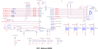
The board have three ethernet ports, one mcu_cpsw, and two ports on Main CPSW.
For now, mcu_cpsw already work normal, but main cpsw ports not work, we used mofiled the dtso file "k3-j7200-evm-quad-port-eth-exp.dtso" as below, which already disabled unused port3 and port4
/dts-v1/; /plugin/; #include <dt-bindings/gpio/gpio.h> #include <dt-bindings/mux/ti-serdes.h> #include <dt-bindings/net/ti-dp83867.h> #include "k3-pinctrl.h" &{/} { aliases { ethernet1 = "/bus@100000/ethernet@c000000/ethernet-ports/port@1"; ethernet2 = "/bus@100000/ethernet@c000000/ethernet-ports/port@2"; //ethernet3 = "/bus@100000/ethernet@c000000/ethernet-ports/port@3"; //ethernet4 = "/bus@100000/ethernet@c000000/ethernet-ports/port@4"; }; }; &cpsw0 { status = "okay"; }; &cpsw0_port1 { status = "okay"; phy-handle = <&cpsw5g_phy0>; phy-mode = "qsgmii"; mac-address = [00 00 00 00 00 00]; phys = <&cpsw0_phy_gmii_sel 1>; }; &cpsw0_port2 { status = "okay"; phy-handle = <&cpsw5g_phy1>; phy-mode = "qsgmii"; mac-address = [00 00 00 00 00 00]; phys = <&cpsw0_phy_gmii_sel 2>; }; &cpsw0_port3 { status = "disabled"; phy-handle = <&cpsw5g_phy2>; phy-mode = "qsgmii"; mac-address = [00 00 00 00 00 00]; phys = <&cpsw0_phy_gmii_sel 3>; }; &cpsw0_port4 { status = "disabled"; phy-handle = <&cpsw5g_phy3>; phy-mode = "qsgmii"; mac-address = [00 00 00 00 00 00]; phys = <&cpsw0_phy_gmii_sel 4>; }; &cpsw5g_mdio { status = "okay"; pinctrl-names = "default"; pinctrl-0 = <&mdio0_pins_default>; //reset-gpios = <&exp2 17 GPIO_ACTIVE_LOW>; //reset-post-delay-us = <120000>; #address-cells = <1>; #size-cells = <0>; cpsw5g_phy0: ethernet-phy@0 { reg = <0>; ti,rx-internal-delay = <DP83867_RGMIIDCTL_2_00_NS>; ti,fifo-depth = <DP83867_PHYCR_FIFO_DEPTH_4_B_NIB>; }; cpsw5g_phy1: ethernet-phy@1 { reg = <1>; ti,rx-internal-delay = <DP83867_RGMIIDCTL_2_00_NS>; ti,fifo-depth = <DP83867_PHYCR_FIFO_DEPTH_4_B_NIB>; }; cpsw5g_phy2: ethernet-phy@18 { reg = <18>; }; cpsw5g_phy3: ethernet-phy@19 { reg = <19>; }; }; /* &exp2 { qsgmii-line-hog { gpio-hog; gpios = <16 GPIO_ACTIVE_HIGH>; output-low; line-name = "qsgmii-pwrdn-line"; }; }; */ &main_pmx0 { mdio0_pins_default: mdio0-pins-default { pinctrl-single,pins = < J721E_IOPAD(0x00a8, PIN_OUTPUT, 5) /* (W19) UART8_TXD.MDIO0_MDC */ J721E_IOPAD(0x00a4, PIN_INPUT, 5) /* (W14) UART8_RXD.MDIO0_MDIO */ >; }; };
and we can see the eth0(mcu_cpsw) and eth1, eth2 on main cpsw by ifconfig command.
root@j7200-evm:~# ifconfig eth0 Link encap:Ethernet HWaddr 58:A1:5F:BE:63:2B UP BROADCAST MULTICAST MTU:1500 Metric:1 RX packets:0 errors:0 dropped:0 overruns:0 frame:0 TX packets:0 errors:0 dropped:0 overruns:0 carrier:0 collisions:0 txqueuelen:1000 RX bytes:0 (0.0 B) TX bytes:0 (0.0 B) eth1 Link encap:Ethernet HWaddr 2E:5A:03:A5:9C:F0 inet addr:192.168.1.10 Bcast:192.168.1.255 Mask:255.255.255.0 inet6 addr: fe80::2c5a:3ff:fea5:9cf0/64 Scope:Link UP BROADCAST RUNNING MULTICAST MTU:1500 Metric:1 RX packets:0 errors:0 dropped:0 overruns:0 frame:0 TX packets:104 errors:0 dropped:0 overruns:0 carrier:0 collisions:0 txqueuelen:1000 RX bytes:0 (0.0 B) TX bytes:11261 (10.9 KiB) eth2 Link encap:Ethernet HWaddr 8E:D0:AF:A7:9F:41 UP BROADCAST MULTICAST MTU:1500 Metric:1 RX packets:0 errors:0 dropped:0 overruns:0 frame:0 TX packets:0 errors:0 dropped:0 overruns:0 carrier:0 collisions:0 txqueuelen:1000 RX bytes:0 (0.0 B) TX bytes:0 (0.0 B) lo Link encap:Local Loopback inet addr:127.0.0.1 Mask:255.0.0.0 inet6 addr: ::1/128 Scope:Host UP LOOPBACK RUNNING MTU:65536 Metric:1 RX packets:192 errors:0 dropped:0 overruns:0 frame:0 TX packets:192 errors:0 dropped:0 overruns:0 carrier:0 collisions:0 txqueuelen:1000 RX bytes:18456 (18.0 KiB) TX bytes:18456 (18.0 KiB)
however, after set ip for eth1 or eth2, it ping failed, and print lots of logs as below.
[ 1977.825539] am65-cpsw-nuss c000000.ethernet eth1: txq:0 DRV_XOFF:0 tmo:1404352 dql_avail:-39 free_desc:505 [ 1982.945537] am65-cpsw-nuss c000000.ethernet eth1: txq:0 DRV_XOFF:0 tmo:1409472 dql_avail:-39 free_desc:505 [ 1988.065539] am65-cpsw-nuss c000000.ethernet eth1: txq:0 DRV_XOFF:0 tmo:1414592 dql_avail:-39 free_desc:505 [ 1994.209536] am65-cpsw-nuss c000000.ethernet eth1: txq:0 DRV_XOFF:0 tmo:1420736 dql_avail:-39 free_desc:505
I have tried to change "phy-mode" to "rgmii", "rgmii-rxid", "rgmii-id", but not work.
attach the dmesg log on boot as below.
root@j7200-evm:~# dmesg |grep ether [ 0.954049] am65-cpsw-nuss 46000000.ethernet: initializing am65 cpsw nuss version 0x6BA02102, cpsw version 0x6BA82102 Ports: 2 quirks:00000000 [ 0.954145] am65-cpsw-nuss 46000000.ethernet: initialized cpsw ale version 1.4 [ 0.954148] am65-cpsw-nuss 46000000.ethernet: ALE Table size 64 [ 0.954583] am65-cpsw-nuss 46000000.ethernet: CPTS ver 0x4e8a010b, freq:500000000, add_val:1 pps:1 [ 0.993237] am65-cpsw-nuss c000000.ethernet: initializing am65 cpsw nuss version 0x6BA02102, cpsw version 0x6BA82102 Ports: 5 quirks:00000000 [ 0.993322] am65-cpsw-nuss c000000.ethernet: Use random MAC address [ 0.993379] am65-cpsw-nuss c000000.ethernet: Use random MAC address [ 0.993388] am65-cpsw-nuss c000000.ethernet: initialized cpsw ale version 1.4 [ 0.993391] am65-cpsw-nuss c000000.ethernet: ALE Table size 512 [ 0.993696] am65-cpsw-nuss c000000.ethernet: CPTS ver 0x4e8a010b, freq:200000000, add_val:4 pps:0 [ 1.062112] am65-cpsw-nuss 46000000.ethernet: initializing am65 cpsw nuss version 0x6BA02102, cpsw version 0x6BA82102 Ports: 2 quirks:00000000 [ 1.062206] am65-cpsw-nuss 46000000.ethernet: initialized cpsw ale version 1.4 [ 1.062209] am65-cpsw-nuss 46000000.ethernet: ALE Table size 64 [ 1.062596] am65-cpsw-nuss 46000000.ethernet: CPTS ver 0x4e8a010b, freq:500000000, add_val:1 pps:1 [ 1.089015] am65-cpsw-nuss 46000000.ethernet: set new flow-id-base 48 [ 1.130501] am65-cpsw-nuss c000000.ethernet: initializing am65 cpsw nuss version 0x6BA02102, cpsw version 0x6BA82102 Ports: 5 quirks:00000000 [ 1.130613] am65-cpsw-nuss c000000.ethernet: Use random MAC address [ 1.130670] am65-cpsw-nuss c000000.ethernet: Use random MAC address [ 1.130679] am65-cpsw-nuss c000000.ethernet: initialized cpsw ale version 1.4 [ 1.130682] am65-cpsw-nuss c000000.ethernet: ALE Table size 512 [ 1.130979] am65-cpsw-nuss c000000.ethernet: CPTS ver 0x4e8a010b, freq:200000000, add_val:4 pps:0 [ 1.157241] am65-cpsw-nuss c000000.ethernet: set new flow-id-base 60 [ 4.680095] am65-cpsw-nuss c000000.ethernet: PSI-L request err -22 [ 4.742143] am65-cpsw-nuss c000000.ethernet eth2: PHY [c000f00.mdio:01] driver [Micrel KSZ9031 Gigabit PHY] (irq=POLL) [ 4.742157] am65-cpsw-nuss c000000.ethernet eth2: configuring for phy/qsgmii link mode [ 4.821078] am65-cpsw-nuss c000000.ethernet eth1: PHY [c000f00.mdio:00] driver [Micrel KSZ9031 Gigabit PHY] (irq=POLL) [ 4.821092] am65-cpsw-nuss c000000.ethernet eth1: configuring for phy/qsgmii link mode [ 4.903243] am65-cpsw-nuss 46000000.ethernet eth0: PHY [46000f00.mdio:02] driver [Micrel KSZ9031 Gigabit PHY] (irq=POLL) [ 4.903257] am65-cpsw-nuss 46000000.ethernet eth0: configuring for phy/rgmii-rxid link mode [ 8.930592] am65-cpsw-nuss c000000.ethernet eth1: Link is Up - 1Gbps/Full - flow control rx/tx
we can see the error message "[ 4.680095] am65-cpsw-nuss c000000.ethernet: PSI-L request err -22" , but don't know why.
For this issue, how can I check next?
BR
guangtao
Hi,
Can you please provide the changes made?
If you need RGMII connection, you need to set the phy-mode as "rgmii" relevant as per delay requirements.
Best Regards,
Sudheer
Yes, we need RGMII connection, and I tried set the phy-mode to "rgmii", but still not work, about the "delay requirements", how can I set it?
BTW, about the changes, you can see below dts "k3-j7200-common-proc-board.dts" and above "k3-j7200-evm-quad-port-eth-exp.dtso" mentioned it the questions.
// SPDX-License-Identifier: GPL-2.0 /* * Copyright (C) 2020 Texas Instruments Incorporated - https://www.ti.com/ */ /dts-v1/; #include "k3-j7200-som-p0.dtsi" #include <dt-bindings/gpio/gpio.h> #include <dt-bindings/net/ti-dp83867.h> #include <dt-bindings/mux/ti-serdes.h> #include <dt-bindings/phy/phy.h> / { compatible = "ti,j7200-evm", "ti,j7200"; model = "[XIVI]Texas Instruments J7200 EVM"; chosen { stdout-path = "serial2:115200n8"; bootargs = "console=ttyS2,115200n8 earlycon=ns16550a,mmio32,0x02800000"; }; evm_12v0: fixedregulator-evm12v0 { /* main supply */ compatible = "regulator-fixed"; regulator-name = "evm_12v0"; regulator-min-microvolt = <12000000>; regulator-max-microvolt = <12000000>; regulator-always-on; regulator-boot-on; }; vsys_3v3: fixedregulator-vsys3v3 { /* Output of LM5140 */ compatible = "regulator-fixed"; regulator-name = "vsys_3v3"; regulator-min-microvolt = <3300000>; regulator-max-microvolt = <3300000>; vin-supply = <&evm_12v0>; regulator-always-on; regulator-boot-on; }; vsys_5v0: fixedregulator-vsys5v0 { /* Output of LM5140 */ compatible = "regulator-fixed"; regulator-name = "vsys_5v0"; regulator-min-microvolt = <5000000>; regulator-max-microvolt = <5000000>; vin-supply = <&evm_12v0>; regulator-always-on; regulator-boot-on; }; vdd_mmc1: fixedregulator-sd { /* Output of TPS22918 */ compatible = "regulator-fixed"; regulator-name = "vdd_mmc1"; regulator-min-microvolt = <3300000>; regulator-max-microvolt = <3300000>; regulator-boot-on; regulator-always-on; //enable-active-high; vin-supply = <&vsys_5v0>; //gpio = <&exp2 2 GPIO_ACTIVE_HIGH>; }; vdd_sd_dv: gpio-regulator-TLV71033 { /* Output of TLV71033 */ status = "disabled"; compatible = "regulator-gpio"; regulator-name = "tlv71033"; pinctrl-names = "default"; pinctrl-0 = <&vdd_sd_dv_pins_default>; regulator-min-microvolt = <1800000>; regulator-max-microvolt = <3300000>; regulator-boot-on; vin-supply = <&vsys_5v0>; gpios = <&main_gpio0 55 GPIO_ACTIVE_HIGH>; states = <1800000 0x0>, <3300000 0x1>; }; transceiver1: can-phy1 { status = "disabled"; compatible = "ti,tcan1043"; #phy-cells = <0>; max-bitrate = <5000000>; pinctrl-names = "default"; pinctrl-0 = <&mcu_mcan0_gpio_pins_default>; standby-gpios = <&wkup_gpio0 58 GPIO_ACTIVE_LOW>; enable-gpios = <&wkup_gpio0 0 GPIO_ACTIVE_HIGH>; }; transceiver2: can-phy2 { status = "disabled"; compatible = "ti,tcan1042"; #phy-cells = <0>; max-bitrate = <5000000>; pinctrl-names = "default"; pinctrl-0 = <&mcu_mcan1_gpio_pins_default>; standby-gpios = <&wkup_gpio0 2 GPIO_ACTIVE_HIGH>; }; transceiver3: can-phy3 { status = "disabled"; compatible = "ti,tcan1043"; #phy-cells = <0>; max-bitrate = <5000000>; standby-gpios = <&exp2 7 GPIO_ACTIVE_LOW>; enable-gpios = <&exp2 6 GPIO_ACTIVE_HIGH>; mux-states = <&mux0 1>; }; }; &wkup_pmx0{ }; &wkup_pmx2 { mcu_uart0_pins_default: mcu-uart0-default-pins { pinctrl-single,pins = < J721E_WKUP_IOPAD(0x90, PIN_INPUT, 0) /* (E20) MCU_UART0_CTSn */ J721E_WKUP_IOPAD(0x94, PIN_OUTPUT, 0) /* (E21) MCU_UART0_RTSn */ J721E_WKUP_IOPAD(0x8c, PIN_INPUT, 0) /* (D20) MCU_UART0_RXD */ J721E_WKUP_IOPAD(0x88, PIN_OUTPUT, 0) /* (D19) MCU_UART0_TXD */ >; }; wkup_uart0_pins_default: wkup-uart0-default-pins { pinctrl-single,pins = < J721E_WKUP_IOPAD(0x48, PIN_INPUT, 0) /* (B14) WKUP_UART0_RXD */ J721E_WKUP_IOPAD(0x4c, PIN_OUTPUT, 0) /* (A14) WKUP_UART0_TXD */ >; }; mcu_cpsw_pins_default: mcu-cpsw-pins-default { pinctrl-single,pins = < J721E_WKUP_IOPAD(0x0000, PIN_OUTPUT, 0) /* MCU_RGMII1_TX_CTL */ J721E_WKUP_IOPAD(0x0004, PIN_INPUT, 0) /* MCU_RGMII1_RX_CTL */ J721E_WKUP_IOPAD(0x0008, PIN_OUTPUT, 0) /* MCU_RGMII1_TD3 */ J721E_WKUP_IOPAD(0x000c, PIN_OUTPUT, 0) /* MCU_RGMII1_TD2 */ J721E_WKUP_IOPAD(0x0010, PIN_OUTPUT, 0) /* MCU_RGMII1_TD1 */ J721E_WKUP_IOPAD(0x0014, PIN_OUTPUT, 0) /* MCU_RGMII1_TD0 */ J721E_WKUP_IOPAD(0x0020, PIN_INPUT, 0) /* MCU_RGMII1_RD3 */ J721E_WKUP_IOPAD(0x0024, PIN_INPUT, 0) /* MCU_RGMII1_RD2 */ J721E_WKUP_IOPAD(0x0028, PIN_INPUT, 0) /* MCU_RGMII1_RD1 */ J721E_WKUP_IOPAD(0x002c, PIN_INPUT, 0) /* MCU_RGMII1_RD0 */ J721E_WKUP_IOPAD(0x0018, PIN_OUTPUT, 0) /* MCU_RGMII1_TXC */ J721E_WKUP_IOPAD(0x001c, PIN_INPUT, 0) /* MCU_RGMII1_RXC */ >; }; wkup_gpio_pins_default: wkup-gpio-pins-default { pinctrl-single,pins = < J721E_WKUP_IOPAD(0x70, PIN_INPUT, 7) /* (C14) WKUP_GPIO0_6 */ >; }; mcu_mdio_pins_default: mcu-mdio1-pins-default { pinctrl-single,pins = < J721E_WKUP_IOPAD(0x0034, PIN_OUTPUT, 0) /* (L1) MCU_MDIO0_MDC */ J721E_WKUP_IOPAD(0x0030, PIN_INPUT, 0) /* (L4) MCU_MDIO0_MDIO */ >; }; mcu_mcan0_pins_default: mcu-mcan0-default-pins { pinctrl-single,pins = < J721E_WKUP_IOPAD(0x54, PIN_INPUT, 0) /* (A17) MCU_MCAN0_RX */ J721E_WKUP_IOPAD(0x50, PIN_OUTPUT, 0) /* (A16) MCU_MCAN0_TX */ >; }; mcu_mcan1_pins_default: mcu-mcan1-default-pins { pinctrl-single,pins = < J721E_WKUP_IOPAD(0x6c, PIN_INPUT, 0) /* (B16) WKUP_GPIO0_5.MCU_MCAN1_RX */ J721E_WKUP_IOPAD(0x68, PIN_OUTPUT, 0) /* (D13) WKUP_GPIO0_4.MCU_MCAN1_TX */ >; }; mcu_mcan0_gpio_pins_default: mcu-mcan0-gpio-default-pins { pinctrl-single,pins = < J721E_WKUP_IOPAD(0x58, PIN_INPUT, 7) /* (B18) WKUP_GPIO0_0 */ J721E_WKUP_IOPAD(0x40, PIN_INPUT, 7) /* (B17) MCU_SPI0_D1 */ >; }; mcu_mcan1_gpio_pins_default: mcu-mcan1-gpio-default-pins { pinctrl-single,pins = < J721E_WKUP_IOPAD(0x60, PIN_INPUT, 7) /* (D14) WKUP_GPIO0_2 */ >; }; }; &main_pmx0 { main_uart0_pins_default: main-uart0-default-pins { pinctrl-single,pins = < J721E_IOPAD(0xb0, PIN_INPUT, 0) /* (T16) UART0_RXD */ J721E_IOPAD(0xb4, PIN_OUTPUT, 0) /* (T17) UART0_TXD */ J721E_IOPAD(0xc0, PIN_INPUT, 2) /* (W3) SPI0_CS0.UART0_CTSn */ J721E_IOPAD(0xc4, PIN_OUTPUT, 2) /* (U5) SPI0_CS1.UART0_RTSn */ >; }; main_i2c0_pins_default: main-i2c0-pins-default { pinctrl-single,pins = < J721E_IOPAD(0xd4, PIN_INPUT_PULLUP, 0) /* (V3) I2C0_SCL */ J721E_IOPAD(0xd8, PIN_INPUT_PULLUP, 0) /* (W2) I2C0_SDA */ >; }; main_i2c1_pins_default: main-i2c1-pins-default { pinctrl-single,pins = < J721E_IOPAD(0xdc, PIN_INPUT_PULLUP, 3) /* (U3) ECAP0_IN_APWM_OUT.I2C1_SCL */ J721E_IOPAD(0xe0, PIN_INPUT_PULLUP, 3) /* (T3) EXT_REFCLK1.I2C1_SDA */ >; }; main_mmc1_pins_default: main-mmc1-pins-default { pinctrl-single,pins = < J721E_IOPAD(0x104, PIN_INPUT, 0) /* (M20) MMC1_CMD */ J721E_IOPAD(0x100, PIN_INPUT, 0) /* (P21) MMC1_CLK */ J721E_IOPAD(0xfc, PIN_INPUT, 0) /* (P25) MMC1_CLKLB */ J721E_IOPAD(0xf8, PIN_INPUT, 0) /* (M19) MMC1_DAT0 */ J721E_IOPAD(0xf4, PIN_INPUT, 0) /* (N21) MMC1_DAT1 */ J721E_IOPAD(0xf0, PIN_INPUT, 0) /* (N20) MMC1_DAT2 */ J721E_IOPAD(0xec, PIN_INPUT, 0) /* (N19) MMC1_DAT3 */ J721E_IOPAD(0xe4, PIN_INPUT, 8) /* (V1) TIMER_IO0.MMC1_SDCD */ >; }; vdd_sd_dv_pins_default: vdd-sd-dv-pins-default { pinctrl-single,pins = < J721E_IOPAD(0xd0, PIN_OUTPUT, 7) /* (T5) SPI0_D1.GPIO0_55 */ >; }; main_mcan3_pins_default: main-mcan3-default-pins { pinctrl-single,pins = < J721E_IOPAD(0x3c, PIN_INPUT, 0) /* (W16) MCAN3_RX */ J721E_IOPAD(0x38, PIN_OUTPUT, 0) /* (Y21) MCAN3_TX */ >; }; }; &main_pmx1 { main_usbss0_pins_default: main-usbss0-pins-default { pinctrl-single,pins = < J721E_IOPAD(0x04, PIN_OUTPUT, 0) /* (T4) USB0_DRVVBUS */ >; }; }; &wkup_uart0 { /* Wakeup UART is used by System firmware */ status = "reserved"; pinctrl-names = "default"; pinctrl-0 = <&wkup_uart0_pins_default>; }; &mcu_uart0 { status = "okay"; /* Default pinmux */ pinctrl-names = "default"; pinctrl-0 = <&mcu_uart0_pins_default>; }; &main_uart0 { status = "okay"; /* Shared with ATF on this platform */ power-domains = <&k3_pds 146 TI_SCI_PD_SHARED>; pinctrl-names = "default"; pinctrl-0 = <&main_uart0_pins_default>; }; &main_uart1 { status = "okay"; /* Default pinmux */ }; &main_uart2 { /* MAIN UART 2 is used by R5F firmware */ status = "disabled"; }; &main_gpio2 { status = "disabled"; }; &main_gpio4 { status = "disabled"; }; &main_gpio6 { status = "disabled"; }; &wkup_gpio0 { pinctrl-names = "default"; pinctrl-0 = <&wkup_gpio_pins_default>; }; &wkup_gpio1 { status = "disabled"; }; &mcu_cpsw { pinctrl-names = "default"; pinctrl-0 = <&mcu_cpsw_pins_default &mcu_mdio_pins_default>; cpts@3d000 { /* Map HW4_TS_PUSH to GENF1 */ ti,pps = <3 1>; }; }; &davinci_mdio { phy0: ethernet-phy@2 { reg = <2>; ti,rx-internal-delay = <DP83867_RGMIIDCTL_2_00_NS>; ti,fifo-depth = <DP83867_PHYCR_FIFO_DEPTH_4_B_NIB>; }; }; &cpsw_port1 { phy-mode = "rgmii-rxid"; phy-handle = <&phy0>; }; &main_i2c0 { status = "disabled"; pinctrl-names = "default"; pinctrl-0 = <&main_i2c0_pins_default>; clock-frequency = <400000>; exp1: gpio@20 { compatible = "ti,tca6416"; reg = <0x20>; gpio-controller; #gpio-cells = <2>; }; exp2: gpio@22 { compatible = "ti,tca6424"; reg = <0x22>; gpio-controller; #gpio-cells = <2>; }; }; /* * The j7200 CPB board is identical to the CPB used for J721E, the SOMs can be * swapped on the CPB. * * main_i2c1 of J7200 is connected to the CPB i2c bus labeled as i2c3. * The i2c1 of the CPB (as it is labeled) is not connected to j7200. */ &main_i2c1 { status = "disabled"; pinctrl-names = "default"; pinctrl-0 = <&main_i2c1_pins_default>; clock-frequency = <400000>; exp3: gpio@20 { compatible = "ti,tca6408"; reg = <0x20>; gpio-controller; #gpio-cells = <2>; gpio-line-names = "CODEC_RSTz", "CODEC_SPARE1", "UB926_RESETn", "UB926_LOCK", "UB926_PWR_SW_CNTRL", "UB926_TUNER_RESET", "UB926_GPIO_SPARE", ""; }; }; &main_sdhci0 { /* eMMC */ non-removable; ti,driver-strength-ohm = <50>; disable-wp; }; &main_sdhci1 { /* SD card */ pinctrl-0 = <&main_mmc1_pins_default>; pinctrl-names = "default"; vmmc-supply = <&vdd_mmc1>; vqmmc-supply = <&vdd_mmc1>; ti,driver-strength-ohm = <50>; no-1-8-v; disable-wp; }; &serdes_ln_ctrl { status = "disabled"; idle-states = <J7200_SERDES0_LANE0_PCIE1_LANE0>, <J7200_SERDES0_LANE1_PCIE1_LANE1>, <J7200_SERDES0_LANE2_QSGMII_LANE1>, <J7200_SERDES0_LANE3_IP4_UNUSED>; }; &usb_serdes_mux { status = "disabled"; idle-states = <1>; /* USB0 to SERDES lane 3 */ }; &usbss0 { status = "disabled"; pinctrl-names = "default"; pinctrl-0 = <&main_usbss0_pins_default>; ti,vbus-divider; ti,usb2-only; }; &usb0 { status = "disabled"; dr_mode = "otg"; maximum-speed = "high-speed"; }; &tscadc0 { status = "disabled"; adc { ti,adc-channels = <0 1 2 3 4 5 6 7>; }; }; &serdes_refclk { clock-frequency = <100000000>; }; &serdes0 { status = "disabled"; serdes0_pcie_link: phy@0 { reg = <0>; cdns,num-lanes = <2>; #phy-cells = <0>; cdns,phy-type = <PHY_TYPE_PCIE>; resets = <&serdes_wiz0 1>, <&serdes_wiz0 2>; }; serdes0_qsgmii_link: phy@1 { reg = <2>; cdns,num-lanes = <1>; #phy-cells = <0>; cdns,phy-type = <PHY_TYPE_QSGMII>; resets = <&serdes_wiz0 3>; }; }; &pcie1_rc { status = "disabled"; reset-gpios = <&exp1 2 GPIO_ACTIVE_HIGH>; phys = <&serdes0_pcie_link>; phy-names = "pcie-phy"; num-lanes = <2>; }; &pcie1_ep { status = "disabled"; phys = <&serdes0_pcie_link>; phy-names = "pcie-phy"; num-lanes = <2>; status = "disabled"; }; &mcu_mcan0 { status = "disabled"; pinctrl-names = "default"; pinctrl-0 = <&mcu_mcan0_pins_default>; phys = <&transceiver1>; }; &mcu_mcan1 { status = "disabled"; pinctrl-names = "default"; pinctrl-0 = <&mcu_mcan1_pins_default>; phys = <&transceiver2>; }; &main_mcan0 { status = "disabled"; }; &main_mcan3 { status = "disabled"; pinctrl-names = "default"; pinctrl-0 = <&main_mcan3_pins_default>; phys = <&transceiver3>; }; #define K3_TS_OFFSET(pa, val) (0x4+(pa)*4) (0x10000 | val) ×ync_router { status = "okay"; pinctrl-names = "default"; pinctrl-0 = <&mcu_cpsw_cpts>; /* Use Time Sync Router to map GENF1 input to HW4_TS_PUSH output */ mcu_cpsw_cpts: mcu-cpsw-cpts { pinctrl-single,pins = < /* pps [mcu cpsw cpts genf1] in17 -> out25 [mcu cpsw cpts hw4_push] */ K3_TS_OFFSET(25, 17) >; }; };
I just disabled some unused devices, such as mcan*, serdes, pcie*.
Hi,
BTW, about the changes, you can see below dts "k3-j7200-common-proc-board.dts" and above "k3-j7200-evm-quad-port-eth-exp.dtso" mentioned it the questions.
You need to configure the CPSW Ports in RGMII Mode.
Also, need to enable Pins for RGMII functionality, refer to "mcu_cpsw_pins_default" from "k3-j7200-common-proc-board.dts" file where CPSW2G pins configured in RGMII Mode.
Yes, we need RGMII connection, and I tried set the phy-mode to "rgmii", but still not work, about the "delay requirements", how can I set it?
Please refer to FAQ for RGMII delay related configuration information.
https://e2e.ti.com/support/processors-group/processors/f/processors-forum/1319345/faq-tda4vm-how-to-configure-rgmii-clock-delay-on-j7-devices
Best Regards,
Sudheer
I have tried to enable Pins for RGMII functionality as below which named "k3-j7200-evm-gesi-proc-board.dtso", and removed unused "serdes", but still not work, it still showing the error message "[ 4.766169] am65-cpsw-nuss c000000.ethernet: [XIVI-RX]PSI-L request err -22".
/dts-v1/; /plugin/; #include <dt-bindings/gpio/gpio.h> #include <dt-bindings/net/ti-dp83867.h> #include "k3-pinctrl.h" &{/} { aliases { ethernet1 = "/bus@100000/ethernet@c000000/ethernet-ports/port@1"; ethernet2 = "/bus@100000/ethernet@c000000/ethernet-ports/port@2"; //ethernet3 = "/bus@100000/ethernet@c000000/ethernet-ports/port@3"; //ethernet4 = "/bus@100000/ethernet@c000000/ethernet-ports/port@4"; }; }; &cpsw0 { status = "okay"; pinctrl-names = "default"; pinctrl-0 = <&rgmii1_pins_default &rgmii2_pins_default>; }; &cpsw0_port1 { status = "okay"; phy-handle = <&cpsw5g_phy0>; phy-mode = "rgmii-rxid"; mac-address = [00 00 00 00 00 00]; phys = <&cpsw0_phy_gmii_sel 1>; }; &cpsw0_port2 { status = "okay"; phy-handle = <&cpsw5g_phy1>; phy-mode = "rgmii-rxid"; mac-address = [00 00 00 00 00 00]; phys = <&cpsw0_phy_gmii_sel 2>; }; &cpsw5g_mdio { status = "okay"; pinctrl-names = "default"; pinctrl-0 = <&mdio0_pins_default>; bus_freq = <1000000>; #address-cells = <1>; #size-cells = <0>; cpsw5g_phy0: ethernet-phy@0 { reg = <0>; ti,rx-internal-delay = <DP83867_RGMIIDCTL_2_00_NS>; ti,fifo-depth = <DP83867_PHYCR_FIFO_DEPTH_4_B_NIB>; ti,min-output-impedance; }; cpsw5g_phy1: ethernet-phy@1 { reg = <1>; ti,rx-internal-delay = <DP83867_RGMIIDCTL_2_00_NS>; ti,fifo-depth = <DP83867_PHYCR_FIFO_DEPTH_4_B_NIB>; ti,min-output-impedance; }; }; &main_pmx0 { mdio0_pins_default: mdio0-pins-default { pinctrl-single,pins = < J721E_IOPAD(0x00a8, PIN_OUTPUT, 5) /* (W19) UART8_TXD.MDIO0_MDC */ J721E_IOPAD(0x00a4, PIN_INPUT, 5) /* (W14) UART8_RXD.MDIO0_MDIO */ >; }; rgmii1_pins_default: rgmii1-pins-default { pinctrl-single,pins = < J721E_IOPAD(0x4, PIN_INPUT, 4) /* (AC23) PRG1_PRU0_GPO0.RGMII1_RD0 */ J721E_IOPAD(0x8, PIN_INPUT, 4) /* (AG22) PRG1_PRU0_GPO1.RGMII1_RD1 */ J721E_IOPAD(0xc, PIN_INPUT, 4) /* (AF22) PRG1_PRU0_GPO2.RGMII1_RD2 */ J721E_IOPAD(0x10, PIN_INPUT, 4) /* (AJ23) PRG1_PRU0_GPO3.RGMII1_RD3 */ J721E_IOPAD(0x1c, PIN_INPUT, 4) /* (AD22) PRG1_PRU0_GPO6.RGMII1_RXC */ J721E_IOPAD(0x14, PIN_INPUT, 4) /* (AH23) PRG1_PRU0_GPO4.RGMII1_RX_CTL */ J721E_IOPAD(0x30, PIN_OUTPUT, 4) /* (AF24) PRG1_PRU0_GPO11.RGMII1_TD0 */ J721E_IOPAD(0x34, PIN_OUTPUT, 4) /* (AJ24) PRG1_PRU0_GPO12.RGMII1_TD1 */ J721E_IOPAD(0x38, PIN_OUTPUT, 4) /* (AG24) PRG1_PRU0_GPO13.RGMII1_TD2 */ J721E_IOPAD(0x3c, PIN_OUTPUT, 4) /* (AD24) PRG1_PRU0_GPO14.RGMII1_TD3 */ J721E_IOPAD(0x44, PIN_OUTPUT, 4) /* (AE24) PRG1_PRU0_GPO16.RGMII1_TXC */ J721E_IOPAD(0x40, PIN_OUTPUT, 4) /* (AC24) PRG1_PRU0_GPO15.RGMII1_TX_CTL */ >; }; rgmii2_pins_default: rgmii2-pins-default { pinctrl-single,pins = < J721E_IOPAD(0x7c, PIN_INPUT, 4) /* (Y13) PRG1_PRU1_GPO0.RGMII2_RD0 */ J721E_IOPAD(0x80, PIN_INPUT, 4) /* (AA15) PRG1_PRU1_GPO1.RGMII2_RD1 */ J721E_IOPAD(0x84, PIN_INPUT, 4) /* (AA14) PRG1_PRU1_GPO2.RGMII2_RD2 */ J721E_IOPAD(0x88, PIN_INPUT, 4) /* (AA18) PRG1_PRU1_GPO3.RGMII2_RD3 */ J721E_IOPAD(0x78, PIN_INPUT, 4) /* (Y14) PRG1_PRU1_GPO6.RGMII2_RXC */ J721E_IOPAD(0x8c, PIN_INPUT, 4) /* (AA16) PRG1_PRU1_GPO4.RGMII2_RX_CTL */ J721E_IOPAD(0x90, PIN_OUTPUT, 4) /* (W17) PRG1_PRU1_GPO11.RGMII2_TD0 */ J721E_IOPAD(0x94, PIN_OUTPUT, 4) /* (W20) PRG1_PRU1_GPO12.RGMII2_TD1 */ J721E_IOPAD(0x98, PIN_OUTPUT, 4) /* (V14) PRG1_PRU1_GPO13.RGMII2_TD2 */ J721E_IOPAD(0x9c, PIN_OUTPUT, 4) /* (V13) PRG1_PRU1_GPO14.RGMII2_TD3 */ J721E_IOPAD(0x28, PIN_OUTPUT, 4) /* (W21) PRG1_PRU1_GPO16.RGMII2_TXC */ J721E_IOPAD(0xa0, PIN_OUTPUT, 4) /* (U12) PRG1_PRU1_GPO15.RGMII2_TX_CTL */ >; }; };
please help check this dtso, is everything ok?
Attach the sch for eth1 of main cpsw.
Hi,
please help check this dtso, is everything ok?
device tree configuration looks file.
it still showing the error message "[ 4.766169] am65-cpsw-nuss c000000.ethernet: [XIVI-RX]PSI-L request err -22".
Can you confirm, ETHFW is not loaded on MCU2_0 core? It can happen only when CPSW5G is controlled/configured by other core.
Best Regards,
Sudheer
How can I check if ETHFW is loaded on MCU2_0 core or not?
U-Boot 2023.04-ti-g196fdae4ccbd (Mar 24 2025 - 13:27:07 +0800) SoC: J7200 SR2.0 GP Model: [XIVI]Texas Instruments K3 J7200 SoC EEPROM not available at 0x50, trying to read at 0x51 Reading on-board EEPROM at 0x51 failed -19 Board: J721EX-PM1-SOM rev E2 DRAM: 2 GiB (effective 4 GiB) Core: 79 devices, 32 uclasses, devicetree: separate Flash: 0 Bytes MMC: mmc@4f80000: 0, mmc@4fb0000: 1 Loading Environment from nowhere... OK In: serial@2800000 Out: serial@2800000 Err: serial@2800000 am65_cpsw_nuss ethernet@46000000: K3 CPSW: nuss_ver: 0x6BA02102 cpsw_ver: 0x6BA82102 ale_ver: 0x00293904 Ports:1 mdio_freq:1000000 EEPROM not available at 0x50, trying to read at 0x51 Reading on-board EEPROM at 0x51 failed -19 Net: eth0: ethernet@46000000port@1 Hit any key to stop autoboot: 0 switch to partitions #0, OK mmc1 is current device SD/MMC found on device 1 Failed to load 'boot.scr' 706 bytes read in 7 ms (97.7 KiB/s) Loaded env from uEnv.txt Importing environment from mmc1 ... i2c_write: error waiting for data ACK (status=0x116) pca953x gpio@20: Error reading output register GPIO: 'gpio@22_17' not found Command 'gpio' failed: Error -22 i2c_write: error waiting for data ACK (status=0x116) pca953x gpio@20: Error reading output register GPIO: 'gpio@22_16' not found Command 'gpio' failed: Error -22 k3_r5f_rproc r5f@41000000: Core 1 is already in use. No rproc commands work Failed to load '/lib/firmware/j7200-mcu-r5f0_1-fw' 576944 bytes read in 34 ms (16.2 MiB/s) Load Remote Processor 2 with data@addr=0x82000000 576944 bytes: Success! Failed to load '/lib/firmware/j7200-main-r5f0_1-fw' 15442432 bytes read in 639 ms (23 MiB/s) 70038 bytes read in 11 ms (6.1 MiB/s) Working FDT set to 88000000 2704 bytes read in 8 ms (330.1 KiB/s) ## Flattened Device Tree blob at 88000000 Booting using the fdt blob at 0x88000000 Working FDT set to 88000000 Loading Device Tree to 000000008feeb000, end 000000008fffffff ... OK Working FDT set to 8feeb000
Above uboot log shows cannot find "/lib/firmware/j7200-mcu-r5f0_1-fw" and "/lib/firmware/j7200-main-r5f0_1-fw", is that means ethfw not loaded yet?
And below dmesgs shows the remoteproc not load firmware "j7200-mcu-r5f0_1-fw", "j7200-main-r5f0_1-fw".
root@j7200-evm:~# dmesg |grep -i remoteproc [ 3.523017] remoteproc remoteproc0: 41000000.r5f is available [ 3.523056] remoteproc remoteproc0: attaching to 41000000.r5f [ 3.556297] remoteproc remoteproc0: remote processor 41000000.r5f is now attached [ 3.558290] platform 41400000.r5f: configured R5F for remoteproc mode [ 3.563978] remoteproc remoteproc1: 41400000.r5f is available [ 3.566790] remoteproc remoteproc1: Direct firmware load for j7200-mcu-r5f0_1-fw failed with error -2 [ 3.566806] remoteproc remoteproc1: powering up 41400000.r5f [ 3.566824] remoteproc remoteproc1: Direct firmware load for j7200-mcu-r5f0_1-fw failed with error -2 [ 3.566828] remoteproc remoteproc1: request_firmware failed: -2 [ 5.605529] remoteproc remoteproc2: 5c00000.r5f is available [ 5.605567] remoteproc remoteproc2: attaching to 5c00000.r5f [ 5.609371] remoteproc remoteproc2: remote processor 5c00000.r5f is now attached [ 5.611684] platform 5d00000.r5f: configured R5F for remoteproc mode [ 5.612449] remoteproc remoteproc3: 5d00000.r5f is available [ 5.612563] remoteproc remoteproc3: Direct firmware load for j7200-main-r5f0_1-fw failed with error -2 [ 5.612570] remoteproc remoteproc3: powering up 5d00000.r5f [ 5.612583] remoteproc remoteproc3: Direct firmware load for j7200-main-r5f0_1-fw failed with error -2 [ 5.612587] remoteproc remoteproc3: request_firmware failed: -2
Thanks for your mentions, I tried remove the default fw in "/lib/firmware/j8200-main-r5f0_0.fw" , then it work fine.
But I still curious about what the use of ethfw, seems it's not necessary?
Hi,
CPSW5G can be controlled by A72 With HLOS like Linux where only A72 can receive and send the data from /through cpsw.
We have another application named ETHFW server controlling CPSW5G and remote clients (Linux/RTOS/Autosar) can also receive and send the data from/to cpsw.
As per your use-case one will choose which application has to runn for CPSW5G.
Best Regards,
Sudheer
I see, so if I don't need remote process, then I just need to remove all ETHFW files, am I right?
Hi,
I see, so if I don't need remote process, then I just need to remove all ETHFW files, am I right?
Yes, If you don't want sharing CPSW with remote clients then you have to disable ETHFW application mapping to MCU2_0 core.
Best Regards,
Sudheer