This thread has been locked.

If you have a related question, please click the "Ask a related question" button in the top right corner. The newly created question will be automatically linked to this question.

AM62L: dsi_p_clk has no rate

Part Number: AM62L
Other Parts Discussed in Thread: AB15

Tool/software:

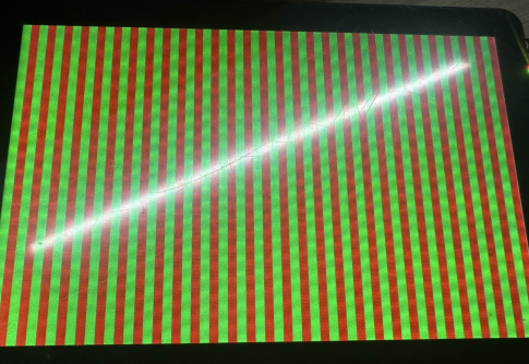
mipi-dsi is connected to the mipi screen, but the screen is not currently displayed.
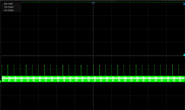
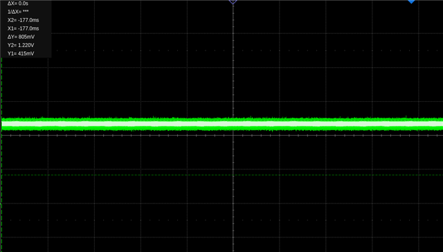
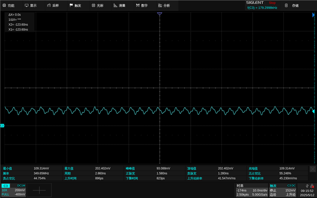
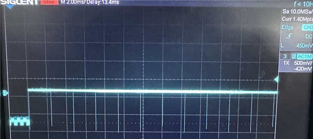
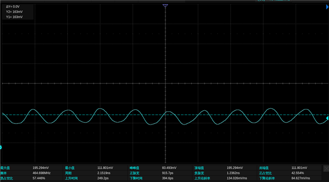
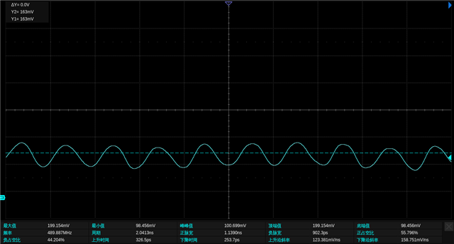
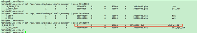
Noticed that dsi_p_clk is not rate, why is this and how can I troubleshoot the problem? Please guide.

Use the command “modetest -M tidss” “cat /sys/kernel/debug/dri/30200000.dss/state” “kmsprint” to see the following:

root@am62lxx-evm:~# kmsprint 
[  984.281069] mipi rad panel get mode 
Connector 0 (41) DSI-1 (connected)
  Encoder 0 (40) NONE
    Crtc 0 (39) 1200x1920@58.53 156.000 1200/80/24/60/- 1920/20/4/10/- 59 (58.53) 0xa 0x48
      Plane 0 (32) fb-id: 43 (crtcs: 0) 0,0 1200x1920 -> 0,0 1200x1920 (AR12 AB12 RA12 RG16 BG16 AR15 AB15 AR24 AB24 RA24 BA24 RG24 BG24 AR30 AB30 XR12 XB12 RX12 XR15 XB15 XR24 XB24 RX24 BX24 XR30 XB30 YUYV UYVY NV12)
        FB 43 1200x1920
root@am62lxx-evm:~# 
root@am62lxx-evm:~# 
root@am62lxx-evm:~# 
root@am62lxx-evm:~# modetest -M tidss
[ 1015.324690] mipi rad panel get mode 
Encoders:
id	crtc	type	possible crtcs	possible clones	
40	39	none	0x00000001	0x00000001

Connectors:
id	encoder	status		name		size (mm)	modes	encoders
41	40	connected	DSI-1          	135x216		1	40
  modes:
	index name refresh (Hz) hdisp hss hse htot vdisp vss vse vtot
  #0 1200x1920 58.53 1200 1280 1304 1364 1920 1940 1944 1954 156000 flags: nhsync, nvsync; type: preferred, driver
  props:
	1 EDID:
		flags: immutable blob
		blobs:

		value:
	2 DPMS:
		flags: enum
		enums: On=0 Standby=1 Suspend=2 Off=3
		value: 0
	5 link-status:
		flags: enum
		enums: Good=0 Bad=1
		value: 0
	6 non-desktop:
		flags: immutable range
		values: 0 1
		value: 0
	4 TILE:
		flags: immutable blob
		blobs:

		value:
	42 panel orientation:
		flags: immutable enum
		enums: Normal=0 Upside Down=1 Left Side Up=2 Right Side Up=3
		value: 0

CRTCs:
id	fb	pos	size
39	43	(0,0)	(1200x1920)
  #0 1200x1920 58.53 1200 1280 1304 1364 1920 1940 1944 1954 156000 flags: nhsync, nvsync; type: preferred, driver
  props:
	24 VRR_ENABLED:
		flags: range
		values: 0 1
		value: 0
	27 CTM:
		flags: blob
		blobs:

		value:
	28 GAMMA_LUT:
		flags: blob
		blobs:

		value:
	29 GAMMA_LUT_SIZE:
		flags: immutable range
		values: 0 4294967295
		value: 256

Planes:
id	crtc	fb	CRTC x,y	x,y	gamma size	possible crtcs
32	39	43	0,0		0,0	0       	0x00000001
  formats: AR12 AB12 RA12 RG16 BG16 AR15 AB15 AR24 AB24 RA24 BA24 RG24 BG24 AR30 AB30 XR12 XB12 RX12 XR15 XB15 XR24 XB24 RX24 BX24 XR30 XB30 YUYV UYVY NV12
  props:
	8 type:
		flags: immutable enum
		enums: Overlay=0 Primary=1 Cursor=2
		value: 1
	30 IN_FORMATS:
		flags: immutable blob
		blobs:

		value:
			01000000000000001d00000018000000
			01000000900000004152313241423132
			52413132524731364247313641523135
			41423135415232344142323452413234
			42413234524732344247323441523330
			41423330585231325842313252583132
			58523135584231355852323458423234
			52583234425832345852333058423330
			59555956555956594e56313200000000
			ffffff1f000000000000000000000000
			0000000000000000
		in_formats blob decoded:
			 AR12:  LINEAR(0x0)
			 AB12:  LINEAR(0x0)
			 RA12:  LINEAR(0x0)
			 RG16:  LINEAR(0x0)
			 BG16:  LINEAR(0x0)
			 AR15:  LINEAR(0x0)
			 AB15:  LINEAR(0x0)
			 AR24:  LINEAR(0x0)
			 AB24:  LINEAR(0x0)
			 RA24:  LINEAR(0x0)
			 BA24:  LINEAR(0x0)
			 RG24:  LINEAR(0x0)
			 BG24:  LINEAR(0x0)
			 AR30:  LINEAR(0x0)
			 AB30:  LINEAR(0x0)
			 XR12:  LINEAR(0x0)
			 XB12:  LINEAR(0x0)
			 RX12:  LINEAR(0x0)
			 XR15:  LINEAR(0x0)
			 XB15:  LINEAR(0x0)
			 XR24:  LINEAR(0x0)
			 XB24:  LINEAR(0x0)
			 RX24:  LINEAR(0x0)
			 BX24:  LINEAR(0x0)
			 XR30:  LINEAR(0x0)
			 XB30:  LINEAR(0x0)
			 YUYV:  LINEAR(0x0)
			 UYVY:  LINEAR(0x0)
			 NV12:  LINEAR(0x0)
	34 zpos:
		flags: range
		values: 0 0
		value: 0
	35 COLOR_ENCODING:
		flags: enum
		enums: ITU-R BT.601 YCbCr=0 ITU-R BT.709 YCbCr=1
		value: 0
	36 COLOR_RANGE:
		flags: enum
		enums: YCbCr limited range=0 YCbCr full range=1
		value: 1
	37 alpha:
		flags: range
		values: 0 65535
		value: 65535
	38 pixel blend mode:
		flags: enum
		enums: Pre-multiplied=0 Coverage=1
		value: 0

Frame buffers:
id	size	pitch

root@am62lxx-evm:~# 
root@am62lxx-evm:~# 
root@am62lxx-evm:~# 
root@am62lxx-evm:~# cat /sys/kernel/debug/dri/30200000.dss/state
plane[32]: plane-0
	crtc=crtc-0
	fb=43
		allocated by = [fbcon]
		refcount=2
		format=XR24 little-endian (0x34325258)
		modifier=0x0
		size=1200x1920
		layers:
			size[0]=1200x1920
			pitch[0]=4800
			offset[0]=0
			obj[0]:
				name=0
				refcount=2
				start=00100000
				size=9216000
				imported=no
				dma_addr=0x00000000bcf00000
				vaddr=000000009718aacd
	crtc-pos=1200x1920+0+0
	src-pos=1200.000000x1920.000000+0.000000+0.000000
	rotation=1
	normalized-zpos=0
	color-encoding=ITU-R BT.601 YCbCr
	color-range=YCbCr full range
	color_mgmt_changed=0
crtc[39]: crtc-0
	enable=1
	active=1
	self_refresh_active=0
	planes_changed=1
	mode_changed=0
	active_changed=0
	connectors_changed=0
	color_mgmt_changed=0
	plane_mask=1
	connector_mask=1
	encoder_mask=1
	mode: "1200x1920": 59 156000 1200 1280 1304 1364 1920 1940 1944 1954 0x48 0xa
connector[41]: DSI-1
	crtc=crtc-0
	self_refresh_aware=0
	max_requested_bpc=0
	colorspace=Default
root@am62lxx-evm:~# 
root@am62lxx-evm:~# 

  • Hi,

    What do you see on the console and on the display using 

    kmstest
    ?

  • We are working on correcting the bug wherein dsi_p_clk does not enumerated, but that should not affect the display functionality.

  • root@am62lxx-evm:~# kmstest
    Connector 0/@41: DSI-1
      Crtc 0/@39: 1200x1920@58.53 156.000 1200/80/24/60/- 1920/20/4/10/- 59 (58.53) 0xa 0x48
      Plane 0/@32: 0,0-1200x1920
        Fb 45 1200x1920-XR24
    press enter to exit
    
    root@am62lxx-evm:~# 
    The display backlight is on, but no image is shown.

    The display backlight is on, but no image is shown.

    Thanks.

  • Hi,

    Can you please check if your issue is similar to this ongoing thread: https://e2e.ti.com/support/processors-group/processors/f/processors-forum/1487601/am62p-q1-mipi-dsi-d-phy-doesn-t-seem-to-be-clocking . If so please, refer to that.

  • Hi,

    1、Does the AM62L MIPI-DSI support 1200x1920 resolution? It's a vertical screen.

    2、Why do some resolutions load fine and others don't, for example when I use my screen's timings it reports an error:

    .clock = 139000,
    .hdisplay = 1200,
    .hsync_start = 1200 + 20,
    .hsync_end = 1200 + 20 + 2,
    .htotal = 1200 + 20 + 2 + 34,
    .vdisplay = 1920,
    .vsync_start = 1920 + 10,
    .vsync_end = 1920 + 10 + 2,
    .vtotal = 1920 + 10 + 2 + 4,
    .width_mm = 135,
    .height_mm = 216,

    [   12.894996] panel-simple panel0: supply power not found, using dummy regulator
    [  OK  ] Listening on Load/Save RF Kill Switch Status /dev/rfkill Watch.
             Starting Load/Save RF Kill Switch Status...
    [   13.384659] [drm] Initialized tidss 1.0.0 for 30200000.dss on minor 0
    [   13.397799] tidss 30200000.dss: [drm] Cannot find any crtc or sizes
             Starting Virtual Console Setup...
    [   13.410404] tidss 30200000.dss: [drm] Cannot find any crtc or sizes

    And when I change the timing a little bit, for example like this, it loads normally, but there is no display and no TX signal is measured.

        .clock = 150000,
        .hdisplay = 1200,
        .hsync_start = 1200 + 80,
        .hsync_end = 1200 + 80 + 24,
        .htotal = 1200 + 80 + 24 + 60,
        .vdisplay = 1920,
        .vsync_start = 1920 + 20,
        .vsync_end = 1920 + 20 + 4,
        .vtotal = 1920 + 20 + 4 + 10,
    [   13.469235] [drm] Initialized tidss 1.0.0 for 30200000.dss on minor 0
    [   13.739774] Console: switching to colour frame buffer device 240x67
    [   13.772004] tidss 30200000.dss: [drm] fb0: tidssdrmfb frame buffer device
    
    
    root@am62lxx-evm:~# fbset
    
    mode "1920x1080"
        geometry 1920 1080 1920 1080 32
        timings 0 0 0 0 0 0 0
        rgba 8/16,8/8,8/0,0/0
    endmode
    
    root@am62lxx-evm:~# 
    3、Is there any limitation on resolution anywhere? For example, if I use “k3-am62l3-evm-dsi-rpi-7inch-panel.dtso”, I can measure the MIPI-DSI-TX signal, but when I change the resolution to 1200x1920, I can't measure the MIPI-DSI-TX signal! .
    My screen only needs to write 7 sets of initialization data in addition to the timing.
        mipi_dsi_generic_write(dsi, (u8[]){ 0xB0, 0x5A }, 2);
        mipi_dsi_generic_write(dsi, (u8[]){ 0xB1, 0x00 }, 2);
        mipi_dsi_generic_write(dsi, (u8[]){ 0x89, 0x01 }, 2);
        mipi_dsi_generic_write(dsi, (u8[]){ 0x2C, 0x28 }, 2);
        mipi_dsi_generic_write(dsi, (u8[]){ 0x00, 0xF1 }, 2);
        mipi_dsi_generic_write(dsi, (u8[]){ 0x11, 0x00 }, 2);
        mipi_dsi_generic_write(dsi, (u8[]){ 0x29, 0x00 }, 2);
  • Does the AM62L MIPI-DSI support 1200x1920 resolution? It's a vertical screen.

    Yes.

    Why do some resolutions load fine and others don't, for example when I use my screen's timings it reports an error:

    Can you please describe your testbench. How are you checking the MIPI-DSI-TX signal? Are the respective panel connected (RPi panel for RPi overlay and your custom panel for custom overlay) with an application running in the background while you probe for the signals?
    Can you also share the output of:

    kmsprint --device=/dev/dri/cardX    # there can be multiple cards in dev/dri.
                                        # share output which shows DSI
    kmstest --device=/dev/dri/cardX     # Do you see anything on screen?

  • Since my screen would not light up, I measured the signal using an oscilloscope and I found that there was no signal from the TX, so I did the following two scenarios, neither of which had the screen connected, but instead measured the signal from the TX directly and using the same tc358762.c driver. My question now is why would just changing the resolution affect the signal output from the TX.

    1、The resolution is 800x480 and the measurement DSI_TX3_N has a data signal:

        .clock = 28569600 / 1000,
        .hdisplay = 800,
        .hsync_start = 800 + 48,
        .hsync_end = 800 + 48 + 32,
        .htotal = 800 + 48 + 32 + 80,
        .vdisplay = 480,
        .vsync_start = 480 + 3,
        .vsync_end = 480 + 3 + 7,
        .vtotal = 480 + 3 + 7 + 6,
    root@am62lxx-evm:~# kmsprint --device=/dev/dri/card0
    Connector 0 (41) DSI-1 (connected)
    Encoder 0 (40) NONE
    Crtc 0 (39) 800x480@60.00 28.569 800/48/32/80/- 480/3/7/6/- 60 (60.00) 0xa 0x48
    Plane 0 (32) fb-id: 42 (crtcs: 0) 0,0 800x480 -> 0,0 800x480 (AR12 AB12 RA12 RG16 BG16 AR15 AB15 AR24 AB24 RA24 BA24 RG24 BG24 AR30 AB30 XR12 XB12 RX12 XR15 XB15 XR24 XB24 RX24 BX24 XR30 XB30 YUYV UYVY NV12)
    FB 42 800x480
    root@am62lxx-evm:~#
    root@am62lxx-evm:~# kmstest --device=/dev/dri/card0
    Connector 0/@41: DSI-1
    Crtc 0/@39: 800x480@60.00 28.569 800/48/32/80/- 480/3/7/6/- 60 (60.00) 0xa 0x48
    Plane 0/@32: 0,0-800x480
    Fb 44 800x480-XR24
    press enter to exit

    root@am62lxx-evm:~#
     
    2、Simply change the resolution to 1280x720 and measure DSI_TX3_N again No data signal:
        .clock = 74250,
        .hdisplay = 1280,
        .hsync_start = 1280 + 110,
        .hsync_end = 1280 + 110 + 40,
        .htotal = 1280 + 110 + 40 + 220,
        .vdisplay = 720,
        .vsync_start = 720 + 5,
        .vsync_end = 720 + 5 + 5,
        .vtotal = 720 + 5 + 5 + 20,
    root@am62lxx-evm:~# kmsprint --device=/dev/dri/card0
    Connector 0 (41) DSI-1 (connected)
      Encoder 0 (40) NONE
        Crtc 0 (39) 1280x720@60.00 74.250 1280/110/40/220/- 720/5/5/20/- 60 (60.00) 0xa 0x48
          Plane 0 (32) fb-id: 42 (crtcs: 0) 0,0 1280x720 -> 0,0 1280x720 (AR12 AB12 RA12 RG16 BG16 AR15 AB15 AR24 AB24 RA24 BA24 RG24 BG24 AR30 AB30 XR12 XB12 RX12 XR15 XB15 XR24 XB24 RX24 BX24 XR30 XB30 YUYV UYVY NV12)
            FB 42 1280x720
    root@am62lxx-evm:~#
    root@am62lxx-evm:~# kmstest --device=/dev/dri/card0
    Connector 0/@41: DSI-1
      Crtc 0/@39: 1280x720@60.00 74.250 1280/110/40/220/- 720/5/5/20/- 60 (60.00) 0xa 0x48
      Plane 0/@32: 0,0-1280x720
        Fb 44 1280x720-XR24
    press enter to exit

    root@am62lxx-evm:~#
    I'd like to know first why changing only the resolution affects the TX signal, in my past debugging, changing only the resolution, the signal should always remain with an output, is there a limit to the resolution somewhere?
  • Also, I changed the lanes in tc358762.c is to 4, so in the first case, DSI_TX3_N has a data signal.

    In the second case, the lanes are also 4.

    That is, the tc358762.c is unchanged during the test signal. The only thing that changes is the resolution from 800x480 > 1280x720; there is no TX data signal for other resolutions. For example 1200x1920.

    @@ -271,7 +283,7 @@ static int tc358762_probe(struct mipi_dsi_device *dsi)
    ctx->pre_enabled = false;

    /* TODO: Find out how to get dual-lane mode working */
    - dsi->lanes = 1;
    + dsi->lanes = 4;
    dsi->format = MIPI_DSI_FMT_RGB888;
    dsi->mode_flags = MIPI_DSI_MODE_VIDEO | MIPI_DSI_MODE_VIDEO_SYNC_PULSE |
    MIPI_DSI_MODE_LPM | MIPI_DSI_MODE_VIDEO_HSE;

  • My guess, other than the timings called in the device tree, are there other places that need to be modified to make the timings I add have outputs, such as other drivers or registers?

  • Hi, thanks for the details.
    I will trying replicating your setup on my end. As per the E2E I shared earlier, we have a ticket raised with the DSI IP provider and will include your test setup observations with them. 

    I'd like to know first why changing only the resolution affects the TX signal, in my past debugging, changing only the resolution, the signal should always remain with an output, is there a limit to the resolution somewhere?

    Custom resolution is supported, but DSI protocol involves an initial handshake with the display (it is not a dumb protocol like OLDI wherein only changing timings/resolution will generate modified signals). If the display is not able to handshake correctly, you ideally should see an error.

    Can you please share your dts and any changes therein related to dss.

  • DSI Device Tree:

    /dts-v1/;
    /plugin/;
    
    #include <dt-bindings/gpio/gpio.h>
    #include <dt-bindings/interrupt-controller/irq.h>
    
    #include "k3-pinctrl.h"
    
    &{/} {
    	bridge_reg: bridge-regulator {
    		compatible = "regulator-fixed";
    		regulator-name = "bt_wake";
    		regulator-min-microvolt = <3300000>;
    		regulator-max-microvolt = <3300000>;
    		enable-active-high;
    		regulator-always-on;
    		regulator-boot-on;
    		vin-supply = <&vcc_3v3_sys>;
    	};
    
    	panel0 {
    		// compatible = "raspberrypi,7inch-dsi", "simple-panel";
    		compatible = "test,7inch-dsi";
    		port {
    			panel_in: endpoint {
    				remote-endpoint = <&panel_bridge_out>;
    			};
    		};
    	};
    };
    
    &dss {
    	status = "okay";
    	bootph-all;
    };
    
    &dss_ports {
    	#address-cells = <1>;
    	#size-cells = <0>;
    
    	port@0 {
    		reg = <0>;
    
    		dpi_out: endpoint {
    			remote-endpoint = <&dsi0_in>;
    		};
    	};
    };
    
    &dphy_tx0 {
    	status = "okay";
    	bootph-all;
    };
    
    &dsi0 {
    	status = "okay";
    	bootph-all;
    	#address-cells = <1>;
    	#size-cells = <0>;
    
    	ports {
    		#address-cells = <1>;
    		#size-cells = <0>;
    
    		port@0 {
    			reg = <0>;
    			dsi0_out: endpoint {
    				remote-endpoint = <&panel_bridge_in>;
    			};
    		};
    
    		port@1 {
    			reg = <1>;
    			dsi0_in: endpoint {
    				remote-endpoint = <&dpi_out>;
    			};
    		};
    	};
    
    	bridge@0 {
    		compatible = "toshiba,tc358762";
    		reg = <0>;
    		vddc-supply = <&bridge_reg>;
    		ports {
    			#address-cells = <1>;
    			#size-cells = <0>;
    
    			port@0 {
    				reg = <0>;
    				panel_bridge_in: endpoint {
    					remote-endpoint = <&dsi0_out>;
    				};
    			};
    
    			port@1 {
    				reg = <1>;
    				panel_bridge_out: endpoint {
    					remote-endpoint = <&panel_in>;
    				};
    			};
    		};
    	};
    };
    

    tc358762.c modified:

    @@ -271,7 +283,7 @@ static int tc358762_probe(struct mipi_dsi_device *dsi)
            ctx->pre_enabled = false;
     
            /* TODO: Find out how to get dual-lane mode working */
    -       dsi->lanes = 1;
    +       dsi->lanes = 4;
            dsi->format = MIPI_DSI_FMT_RGB888;

    panel-simple.c add 1280x720:

    --- a/drivers/gpu/drm/panel/panel-simple.c
    +++ b/drivers/gpu/drm/panel/panel-simple.c
    @@ -3880,6 +3880,32 @@ static const struct panel_desc raspberrypi_7inch = {
            .connector_type = DRM_MODE_CONNECTOR_DSI,
     };
     
    +static const struct drm_display_mode test_7inch_mode = {
    +       .clock = 74250,
    +       .hdisplay = 1280,
    +       .hsync_start = 1280 + 110,
    +       .hsync_end = 1280 + 110 + 40,
    +       .htotal = 1280 + 110 + 40 + 220,
    +       .vdisplay = 720,
    +       .vsync_start = 720 + 5,
    +       .vsync_end = 720 + 5 + 5,
    +       .vtotal = 720 + 5 + 5 + 20,
    +
    +       .flags = DRM_MODE_FLAG_NVSYNC | DRM_MODE_FLAG_NHSYNC,
    +};
    +
    +static const struct panel_desc test_7inch = {
    +       .modes = &test_7inch_mode,
    +       .num_modes = 1,
    +       .bpc = 8,
    +       .size = {
    +               .width = 154,
    +               .height = 86,
    +       },
    +       .bus_format = MEDIA_BUS_FMT_RGB888_1X24,
    +       .connector_type = DRM_MODE_CONNECTOR_DSI,
    +};
    +
     static const struct display_timing rocktech_rk070er9427_timing = {
            .pixelclock = { 26400000, 33300000, 46800000 },
            .hactive = { 800, 800, 800 },
    @@ -5007,6 +5033,9 @@ static const struct of_device_id platform_of_match[] = {
                    .compatible = "raspberrypi,7inch-dsi",
                    .data = &raspberrypi_7inch,
            }, {
    +               .compatible = "test,7inch-dsi",
    +               .data = &test_7inch,
    +       },{
                    .compatible = "rocktech,rk070er9427",
                    .data = &rocktech_rk070er9427,
            }, {

    Only these three changes were made, nothing else was altered.

    When in the device tree compatible = “raspberrypi,7inch-dsi”, “simple-panel”; DSI-TX measurements have a data signal.
    When compatible = “test,7inch-dsi”; the DSI-TX measures no data signal.

    Thanks

  • Thanks. I will try replicating your setup on my end and get back to you by mid-next week.
    Meanwhile, I will keep you updated on any feedback we get from DSI IP provider.

  • Thanks, looking forward to your good news.

  • What is the value of this register for you?
    DSI_VBUSP_CFG_DSI_0_DSI_VID_MODE_STS (0x305000F0)

    Can you also try applying this patch series: https://lore.kernel.org/all/20250320-cdns-dsi-impro-v1-18-725277c5f43b@ideasonboard.com/#r 
    It may not be a clean apply and few things may need to be backported.

  • Thank you for your reply.

    When the resolution is set to 800x480, the value read from this register is 0x1.

    When the resolution is set to 1280x720, the value read from this register is 0x4.

    This patch did not resolve the issue. After changing the resolution, there is no DSI-TX signal. Have you tested other resolutions?

  • Thanks.
    Please stay tuned. We are debugging this issue. Will keep you posted with any updates.

  • Hi,
    Please carry out the experiment mentioned under example of sequence under section: 12.7.2.7.7.4 TVG Configuration of the TRM (https://www.ti.com/lit/pdf/sprujb4) and share your results.

    Meanwhile, I am also conducting the same on my end.

  • No signal output was detected during testing, and the screen no display.

  • Yes, I noticed this post during testing. I ran the test and there was no output.

    root@am62lxx-evm:~# ./dsi_test.sh 
    DSI_VID_VSIZE1
    Unknown Silicon 48039
    Value at addr 0x305000b4 = 0x14245
    DSI_VID_VSIZE2
    Unknown Silicon 48039
    Value at addr 0x305000b8 = 0x780
    DSI_VID_HSIZE1
    Unknown Silicon 48039
    Value at addr 0x305000c0 = 0xa8003a
    DSI_VID_HSIZE2
    Unknown Silicon 48039
    Value at addr 0x305000c4 = 0xea0e10
    DSI_VID_BLKSIZE1
    Unknown Silicon 48039
    Value at addr 0x305000cc = 0xff2
    DSI_VID_BLKSIZE2
    Unknown Silicon 48039
    Value at addr 0x305000d0 = 0xfae
    DSI_VID_PCK_TIME
    Unknown Silicon 48039
    Value at addr 0x305000d8 = 0x0
    DSI_VID_DPHY_TIME
    Unknown Silicon 48039
    Value at addr 0x305000dc = 0x87603ef
    DSI_VID_MODE_STS
    Unknown Silicon 48039
    Value at addr 0x305000f0 = 0x30
    DSI_VID_VCA_SETTING1
    Unknown Silicon 48039
    Value at addr 0x305000f4 = 0x0
    DSI_VID_VCA_SETTING2
    Unknown Silicon 48039
    Value at addr 0x305000f8 = 0xfa80000
    DSI_TVG_CTL
    Unknown Silicon 48039
    Value at addr 0x305000fc = 0xb9
    DSI_TVG_IMG_SIZE
    Unknown Silicon 48039
    Value at addr 0x30500100 = 0x5000870
    DSI_TVG_COLOR1
    Unknown Silicon 48039
    Value at addr 0x30500104 = 0xff0000
    DSI_TVG_COLOR1_BIS
    Unknown Silicon 48039
    Value at addr 0x30500108 = 0x0
    DSI_TVG_COLOR2
    Unknown Silicon 48039
    Value at addr 0x3050010c = 0xfff
    DSI_TVG_COLOR2_BIS
    Unknown Silicon 48039
    Value at addr 0x30500110 = 0x0
    DSI_TVG_STS
    Unknown Silicon 48039
    Value at addr 0x30500114 = 0x1
    DSI_MAIN_DATA_CTL
    Unknown Silicon 48039
    Value at addr 0x30500004 = 0x20067
    DSI_MCTL_MAIN_EN
    Unknown Silicon 48039
    Value at addr 0x3050000c = 0xf9
    -------- Enabling test pattern
    DSI_TVG_CTL WRITE (disable TVG_RUN)
    Unknown Silicon 48039
    Value at addr 0x305000fc = 0xb8
    DSI_MCTL_MAIN_EN WRITE (disable IF2_EN)
    Unknown Silicon 48039
    Value at addr 0x3050000c = 0xf9
    DSI_MAIN_DATA_CTL WRITE (enable TVG, disable VID_EN)
    Unknown Silicon 48039
    Value at addr 0x30500004 = 0x20047
    DSI_MAIN_DATA_CTL WRITE (enable TVG, enable VID_EN)
    Unknown Silicon 48039
    Value at addr 0x30500004 = 0x20067
    DSI_TVG_IMG_SIZE WRITE (setup lines / size 720x1280)
    Unknown Silicon 48039
    Value at addr 0x30500100 = 0x5000870
    TEST PATTERN COLOR 1
    Unknown Silicon 48039
    Value at addr 0x30500104 = 0xff0000
    Unknown Silicon 48039
    Value at addr 0x30500108 = 0x0
    TEST PATTERN COLOR 2
    Unknown Silicon 48039
    Value at addr 0x3050010c = 0xfff
    Unknown Silicon 48039
    Value at addr 0x30500110 = 0x0
    DSI_TVG_CTL WRITE (enable TVG_RUN)
    Unknown Silicon 48039
    Value at addr 0x305000fc = 0xb9
    DSI_TVG_STS
    Unknown Silicon 48039
    Value at addr 0x30500114 = 0x1
    root@am62lxx-evm:~# 
    root@am62lxx-evm:~# 
    root@am62lxx-evm:~# 
    root@am62lxx-evm:~# kmsprint 
    Connector 0 (41) DSI-1 (connected)
      Encoder 0 (40) NONE
        Crtc 0 (39) 1200x1920@56.28 150.000 1200/80/24/60/- 1920/20/4/10/- 56 (56.28) 0xa 0x48
          Plane 0 (32) fb-id: 42 (crtcs: 0) 0,0 1200x1920 -> 0,0 1200x1920 (AR12 AB12 RA12 RG16 BG16 AR15 AB15 AR24 AB24 RA24 BA24 RG24 BG24 AR30 AB30 XR12 XB12 RX12 XR15 XB15 XR24 XB24 RX24 BX24 XR30 XB30 YUYV UYVY NV12)
            FB 42 1200x1920
    root@am62lxx-evm:~# 

  • Hi,
    Can you please try the following:
    1. Incorporated the patch: Patch 15/18 of the previously mentioned patchset. 
    2. Adjust the REG_BLKEOL_MODE and REG_BLKLINE_MODE to 3 (switch to LP mode vs. transmit blank packets) in register 2.2.35.1 DSI_TOP_VBUSP_CFG_DSI_0_DSI_VID_MAIN_CTL Register (Offset = B0h) [reset = 80000000h]

    And share if display works after this?

  • Hi,

    Still no effect, no DSI_TX data signal

    root@am62lxx-evm:~# ./dsi_test.sh 
    DSI_VID_VSIZE1
    Unknown Silicon 48039
    Value at addr 0x305000b4 = 0x14245
    DSI_VID_VSIZE2
    Unknown Silicon 48039
    Value at addr 0x305000b8 = 0x780
    DSI_VID_HSIZE1
    Unknown Silicon 48039
    Value at addr 0x305000c0 = 0xa8003a
    DSI_VID_HSIZE2
    Unknown Silicon 48039
    Value at addr 0x305000c4 = 0xea0e10
    DSI_VID_BLKSIZE1
    Unknown Silicon 48039
    Value at addr 0x305000cc = 0xff2
    DSI_VID_BLKSIZE2
    Unknown Silicon 48039
    Value at addr 0x305000d0 = 0xfae
    DSI_VID_PCK_TIME
    Unknown Silicon 48039
    Value at addr 0x305000d8 = 0x0
    DSI_VID_DPHY_TIME
    Unknown Silicon 48039
    Value at addr 0x305000dc = 0x87603ef
    DSI_VID_MODE_STS
    Unknown Silicon 48039
    Value at addr 0x305000f0 = 0x4
    DSI_VID_VCA_SETTING1
    Unknown Silicon 48039
    Value at addr 0x305000f4 = 0x0
    DSI_VID_VCA_SETTING2
    Unknown Silicon 48039
    Value at addr 0x305000f8 = 0xfa80000
    DSI_TVG_CTL
    Unknown Silicon 48039
    Value at addr 0x305000fc = 0x0
    DSI_TVG_IMG_SIZE
    Unknown Silicon 48039
    Value at addr 0x30500100 = 0x0
    DSI_TVG_COLOR1
    Unknown Silicon 48039
    Value at addr 0x30500104 = 0x0
    DSI_TVG_COLOR1_BIS
    Unknown Silicon 48039
    Value at addr 0x30500108 = 0x0
    DSI_TVG_COLOR2
    Unknown Silicon 48039
    Value at addr 0x3050010c = 0x0
    DSI_TVG_COLOR2_BIS
    Unknown Silicon 48039
    Value at addr 0x30500110 = 0x0
    DSI_TVG_STS
    Unknown Silicon 48039
    Value at addr 0x30500114 = 0x0
    DSI_MAIN_DATA_CTL
    Unknown Silicon 48039
    Value at addr 0x30500004 = 0x20027
    DSI_MCTL_MAIN_EN
    Unknown Silicon 48039
    Value at addr 0x3050000c = 0x40f9
     DSI_TOP_VBUSP_CFG_DSI_0_DSI_VID_MAIN_CTL
    Unknown Silicon 48039
    Value at addr 0x305000b0 = 0x80b8fe00
    -------- Enabling test pattern
    DSI_TVG_CTL WRITE (disable TVG_RUN)
    Unknown Silicon 48039
    Value at addr 0x305000fc = 0xb8
    DSI_MCTL_MAIN_EN WRITE (disable IF2_EN)
    Unknown Silicon 48039
    Value at addr 0x3050000c = 0xf9
    DSI_MAIN_DATA_CTL WRITE (enable TVG, disable VID_EN)
    Unknown Silicon 48039
    Value at addr 0x30500004 = 0x20047
    DSI_MAIN_DATA_CTL WRITE (enable TVG, enable VID_EN)
    Unknown Silicon 48039
    Value at addr 0x30500004 = 0x20067
    DSI_TVG_IMG_SIZE WRITE (setup lines / size 720x1280)
    Unknown Silicon 48039
    Value at addr 0x30500100 = 0x5000870
    TEST PATTERN COLOR 1
    Unknown Silicon 48039
    Value at addr 0x30500104 = 0xff0000
    Unknown Silicon 48039
    Value at addr 0x30500108 = 0x0
    TEST PATTERN COLOR 2
    Unknown Silicon 48039
    Value at addr 0x3050010c = 0xfff
    Unknown Silicon 48039
    Value at addr 0x30500110 = 0x0
    DSI_TVG_CTL WRITE (enable TVG_RUN)
    Unknown Silicon 48039
    Value at addr 0x305000fc = 0xb9
    DSI_TVG_STS
    Unknown Silicon 48039
    Value at addr 0x30500114 = 0x1
    REG_BLKEOL_MODE & ​​REG_BLKLINE_MODE : 3
    Unknown Silicon 48039
    Value at addr 0x305000b0 = 0x81f8fe00
    root@am62lxx-evm:~#

  • Hi,

    Thanks for the info. We have relayed your issues and debug outputs to our DSI IP partner and are waiting for them to share next steps. Will keep you posted as and when we receive inputs.

  • Here is the response from IP provider:
    "could you please ask this customer to measure the clock lane rate/byte clock if possible. Also please check if there are LP11 states for every end of frame on the data lane in scope.  + confirm the LCD panel is healthy with another source.
    please capture the data lane and clock lane at first place in scope. Keep long duration which accommodate 480 lines of stop state (increase the timescale), you see a longer stop state in scope than the one smaller one and add time cursors between these stop states.
    "

    Please capture this for both clock and data lines for both the working and non-working resolutions.

  • Hi,

    I have already measured the signals in previous responses. ​​

    When the screen resolution is 800x480​​, the display works normally, and both data and clock signals can be measured.

    When the screen resolution is 1280x720, the clock signal is present, but there is no ​​DSI_TX data signal​​. I have confirmed that the screen works properly on other development boards. How do I check the ​​LP11 state​​?

  • Still no effect, no DSI_TX data signal

    Hi,
    Is your panel 4-lane - 60 fps, rgb888 or 1-lane?


    Please rerun this test (TVG generator) with modified parameters (The script made by other user was for 720x1280 and not 1280x720).

    1. Following was your timing parameter.
    .clock = 74250 
        .hdisplay = 1280,
        .hsync_start = 1280 + 110,
        .hsync_end = 1280 + 110 + 40,
        .htotal = 1280 + 110 + 40 + 220,
        .vdisplay = 720,
        .vsync_start = 720 + 5,
        .vsync_end = 720 + 5 + 5,
        .vtotal = 720 + 5 + 5 + 20,
     
    //write these registers (it’s not recommended, just for debug)
    2. update TVG_IMG_SIZE ----> register value: [vdisplay <<16 |  3*hdisplay],
    3. Configure Color1,2.
    4. kick off TVG RUN.

    Please dump the registers again and share what you see on screen/probe
  • Hi,

    1、4-lane configuration with 60 fps​​ is used.

    2、After following your instructions, the ​​DSI_TX signal​​ can be measured. The waveforms of ​​DSI0_TXN​​ and ​​DSI0_TXP​​ appear identical, as shown in the figure below. However, the ​​polarity seems inverted​​? Not displayed

    3、How is the value of ​​DSI_TVG_IMG_SIZE​​ calculated? I could not find the relevant calculation method in the manual. If I want to test with a ​​1200x1920 screen​​, how should I calculate the value of ​​DSI_TVG_IMG_SIZE​​?

  • After following your instructions, the ​​DSI_TX signal​​ can be measured.

    If you didn't modify DSI_TVG_IMG_SIZE, what other changes did you do?

    [vdisplay <<16 |  3*hdisplay],

    I have already shared how to calculate DSI_TVG_IMG_SIZE.
    For 1280x720, vdisplay=720 and hdisplay=1280, 
    Iterating again; DSI_TVG_IMG_SIZE value = {leftshift(vdisplay, 16 times) |binary OR| (3 times the value of hdisplay)}

    attaching register bit settings for your reference.


    For 1200x1920 screen, vdisplay=1920 and hdisplay=1200.

    Please also specify which screen you are targeting, 1280x720(horizontal) or 1200x1920 (vertical).
    If using the latter, please share the timing parameters too.

  • Thanks.

    No other modifications were made. Details are as follows:

    root@am62lxx-evm:~# cat dsi.sh 
    #!/bin/sh
    
    echo "REG_BLKEOL_MODE & ​​REG_BLKLINE_MODE : 3"              
    k3conf write 0x305000B0 0x81F8FE00 | grep addr
    echo "-------- Enabling test pattern"
    echo "DSI_TVG_CTL WRITE (disable TVG_RUN)"
    k3conf write 0x305000fc 0x000000B8 | grep addr
    sleep 1
    echo "DSI_MCTL_MAIN_EN WRITE (disable IF2_EN)"
    k3conf write 0x3050000C 0x000000F9 | grep addr 
    echo "DSI_MAIN_DATA_CTL WRITE (enable TVG, disable VID_EN)"
    k3conf write 0x30500004 0x00020047 | grep addr 
    sleep 1
    echo "DSI_MAIN_DATA_CTL WRITE (enable TVG, enable VID_EN)"
    k3conf write 0x30500004 0x00020067 | grep addr 
    echo "DSI_TVG_IMG_SIZE WRITE (setup lines / size 1200x1920)"
    k3conf write 0x30500100 0x07800E10 | grep addr 
    echo "TEST PATTERN COLOR 1"
    k3conf write 0x30500104 0x0FFF0000 | grep addr 
    k3conf write 0x30500108 0x00000000 | grep addr 
    echo "TEST PATTERN COLOR 2"
    k3conf write 0x3050010c 0x00000FFF | grep addr 
    k3conf write 0x30500110 0x00000000 | grep addr 
    echo "DSI_TVG_CTL WRITE (enable TVG_RUN)"
    k3conf write 0x305000fc 0x000000B9 | grep addr 


    root@am62lxx-evm:~# 
    root@am62lxx-evm:~# 
    root@am62lxx-evm:~# 
    root@am62lxx-evm:~# ./dsi.sh 
    REG_BLKEOL_MODE & ​​REG_BLKLINE_MODE : 3
    Unknown Silicon 48039
    Value at addr 0x305000b0 = 0x81f8fe00
    -------- Enabling test pattern
    DSI_TVG_CTL WRITE (disable TVG_RUN)
    Unknown Silicon 48039
    Value at addr 0x305000fc = 0xb8
    DSI_MCTL_MAIN_EN WRITE (disable IF2_EN)
    Unknown Silicon 48039
    Value at addr 0x3050000c = 0xf9
    DSI_MAIN_DATA_CTL WRITE (enable TVG, disable VID_EN)
    Unknown Silicon 48039
    Value at addr 0x30500004 = 0x20047
    DSI_MAIN_DATA_CTL WRITE (enable TVG, enable VID_EN)
    Unknown Silicon 48039
    Value at addr 0x30500004 = 0x20067
    DSI_TVG_IMG_SIZE WRITE (setup lines / size 1200x1920)
    Unknown Silicon 48039
    Value at addr 0x30500100 = 0x7800e10
    TEST PATTERN COLOR 1
    Unknown Silicon 48039
    Value at addr 0x30500104 = 0xff0000
    Unknown Silicon 48039
    Value at addr 0x30500108 = 0x0
    TEST PATTERN COLOR 2
    Unknown Silicon 48039
    Value at addr 0x3050010c = 0xfff
    Unknown Silicon 48039
    Value at addr 0x30500110 = 0x0
    DSI_TVG_CTL WRITE (enable TVG_RUN)
    Unknown Silicon 48039
    Value at addr 0x305000fc = 0xb9
    root@am62lxx-evm:~# 
    root@am62lxx-evm:~# 
    root@am62lxx-evm:~# 
    root@am62lxx-evm:~# kmsprint 
    Connector 0 (41) DSI-1 (connected)
      Encoder 0 (40) NONE
        Crtc 0 (39) 1200x1920@56.28 150.000 1200/80/24/60/- 1920/20/4/10/- 56 (56.28) 0xa 0x48
          Plane 0 (32) fb-id: 42 (crtcs: 0) 0,0 1200x1920 -> 0,0 1200x1920 (AR12 AB12 RA12 RG16 BG16 AR15 AB15 AR24 AB24 RA24 BA24 RG24 BG24 AR30 AB30 XR12 XB12 RX12 XR15 XB15 XR24 XB24 RX24 BX24 XR30 XB30 YUYV UYVY NV12)
            FB 42 1200x1920
    root@am62lxx-evm:~# 
    root@am62lxx-evm:~# 

    timing:

    static const struct drm_display_mode qunxin_1200x1920_mode = {
    	.clock = 150000,
    	.hdisplay = 1200,
    	.hsync_start = 1200 + 80,
    	.hsync_end = 1200 + 80 + 24,
    	.htotal = 1200 + 80 + 24 + 60,
    	.vdisplay = 1920,
    	.vsync_start = 1920 + 20,
    	.vsync_end = 1920 + 20 + 4,
    	.vtotal = 1920 + 20 + 4 + 10,
    
    	.flags = DRM_MODE_FLAG_NVSYNC | DRM_MODE_FLAG_NHSYNC,
    };
    
    static const struct panel_desc qunxin_1200x1920 = {
    	.modes = &qunxin_1200x1920_mode,
    	.num_modes = 1,
    	.bpc = 8,
    	.size = {
    		.width = 135,
    		.height = 216,
    	},
    	.bus_format = MEDIA_BUS_FMT_RGB888_1X24,
    	.connector_type = DRM_MODE_CONNECTOR_DSI,
    };

    DSI_TX Waveform:

  • Do you see anything on display?

  • There is no display, and the waveform is inverted compared to normal operation. Could this be an issue? Additionally, there are intermittent instances where the waveform is completely absent.

  • Hi,

    I updated the device tree driver, and after executing the scripts, the display now works.

    dts:

    &dss {
    	status = "okay";
    	bootph-all;
    };
    
    &dss_ports {
    	#address-cells = <1>;
    	#size-cells = <0>;
    
    	port@0 {
    		reg = <0>;
    
    		dpi_out: endpoint {
    			remote-endpoint = <&dsi0_in>;
    		};
    	};
    };
    
    &dphy_tx0 {
    	status = "okay";
    	bootph-all;
    };
    
    &dsi0 {
    	status = "okay";
    	bootph-all;
    	#address-cells = <1>;
    	#size-cells = <0>;
    
    	ports {
    		#address-cells = <1>;
    		#size-cells = <0>;
    
    		port@0 {
    			reg = <0>;
    			dsi0_out: endpoint {
    				remote-endpoint = <&panel_in>;
    			};
    		};
    
    		port@1 {
    			reg = <1>;
    			dsi0_in: endpoint {
    				remote-endpoint = <&dpi_out>;
    			};
    		};
    	};
    
    	panel@0 {
    		compatible = "qunxin,cg10132010";
    		v3p3-supply = <&vcc_3v3_sys>;
    		v1p8-supply = <&vcc_1v8>;
    		reg = <0>;
    		ports {
    			#address-cells = <1>;
    			#size-cells = <0>;
    
    			port@0 {
    				reg = <0>;
    				panel_in: endpoint {
    					remote-endpoint = <&dsi0_out>;
    				};
    			};
    		};
    	};
    };

    dsi_test

    root@am62lxx-evm:~# 
    root@am62lxx-evm:~# cat dsi.sh 
    #!/bin/sh
    
    echo "REG_BLKEOL_MODE & ​​REG_BLKLINE_MODE : 3"              
    k3conf write 0x305000B0 0x81F8FE00 | grep addr
    echo "-------- Enabling test pattern"
    echo "DSI_TVG_CTL WRITE (disable TVG_RUN)"
    k3conf write 0x305000fc 0x000000B8 | grep addr
    sleep 1
    echo "DSI_MCTL_MAIN_EN WRITE (disable IF2_EN)"
    k3conf write 0x3050000C 0x000000F9 | grep addr 
    echo "DSI_MAIN_DATA_CTL WRITE (enable TVG, disable VID_EN)"
    k3conf write 0x30500004 0x00020047 | grep addr 
    sleep 1
    echo "DSI_MAIN_DATA_CTL WRITE (enable TVG, enable VID_EN)"
    k3conf write 0x30500004 0x00020067 | grep addr 
    echo "DSI_TVG_IMG_SIZE WRITE (setup lines / size 1200x1920)"
    k3conf write 0x30500100 0x07800E10 | grep addr 
    echo "TEST PATTERN COLOR 1"
    k3conf write 0x30500104 0x0FFF0000 | grep addr 
    k3conf write 0x30500108 0x00000000 | grep addr 
    echo "TEST PATTERN COLOR 2"
    k3conf write 0x3050010c 0x00000FFF | grep addr 
    k3conf write 0x30500110 0x00000000 | grep addr 
    echo "DSI_TVG_CTL WRITE (enable TVG_RUN)"
    k3conf write 0x305000fc 0x000000B9 | grep addr 


    root@am62lxx-evm:~# ./dsi.sh 
    REG_BLKEOL_MODE & ​​REG_BLKLINE_MODE : 3
    Unknown Silicon 48039
    Value at addr 0x305000b0 = 0x81f8fe00
    -------- Enabling test pattern
    DSI_TVG_CTL WRITE (disable TVG_RUN)
    Unknown Silicon 48039
    Value at addr 0x305000fc = 0xb8
    DSI_MCTL_MAIN_EN WRITE (disable IF2_EN)
    Unknown Silicon 48039
    Value at addr 0x3050000c = 0xf9
    DSI_MAIN_DATA_CTL WRITE (enable TVG, disable VID_EN)
    Unknown Silicon 48039
    Value at addr 0x30500004 = 0x20047
    DSI_MAIN_DATA_CTL WRITE (enable TVG, enable VID_EN)
    Unknown Silicon 48039
    Value at addr 0x30500004 = 0x20067
    DSI_TVG_IMG_SIZE WRITE (setup lines / size 1200x1920)
    Unknown Silicon 48039
    Value at addr 0x30500100 = 0x7800e10
    TEST PATTERN COLOR 1
    Unknown Silicon 48039
    Value at addr 0x30500104 = 0xff0000
    Unknown Silicon 48039
    Value at addr 0x30500108 = 0x0
    TEST PATTERN COLOR 2
    Unknown Silicon 48039
    Value at addr 0x3050010c = 0xfff
    Unknown Silicon 48039
    Value at addr 0x30500110 = 0x0
    DSI_TVG_CTL WRITE (enable TVG_RUN)
    Unknown Silicon 48039
    Value at addr 0x305000fc = 0xb9
    root@am62lxx-evm:~# 

    What steps should I take next to test to get my screen to display directly?

    Thanks

  • Since you have updated the driver, reboot and check does kmstest show something on screen?

  • After testing, if the script is not executed upon startup and kmstest is run, the screen does not display any other content. Only after executing the script does this color display appear.

    Additionally, the DSI_TX signal cannot be measured before executing the script, but it becomes detectable only after the script is executed.

    root@am62lxx-evm:~# kmstest
    Connector 0/@41: DSI-1
      Crtc 0/@39: 1200x1920@60.00 159.916 1200/80/24/60/- 1920/20/4/10/- 60 (60.00) 0xa 0x48
      Plane 0/@32: 0,0-1200x1920
        Fb 44 1200x1920-XR24
    press enter to exit
  • Can you please try the following:
    1. Incorporated the patch: Patch 15/18 of the previously mentioned patchset. 
    2. Adjust the REG_BLKEOL_MODE and REG_BLKLINE_MODE to 3 (switch to LP mode vs. transmit blank packets) in register 2.2.35.1 DSI_TOP_VBUSP_CFG_DSI_0_DSI_VID_MAIN_CTL Register (Offset = B0h) [reset = 80000000h]

    Can you please retry these steps again. Since TVG generator is working, this may work.

  • During the testing process above, I have already added the patch to drivers/gpu/drm/bridge/cadence/cdns-dsi-core.c. Additionally, REG_BLKEOL_MODE and REG_BLKLINE_MODE have been included in the script.

     #ifdef CONFIG_DRM_CDNS_DSI_J721E
     #include "cdns-dsi-j721e.h"
    @@ -972,6 +972,28 @@ static u32 *cdns_dsi_bridge_get_input_bus_fmts(struct drm_bridge *bridge,
            return input_fmts;
     }
     
    +static long cdns_dsi_round_pclk(struct cdns_dsi *dsi, unsigned long pclk)
    +{
    +       struct cdns_dsi_output *output = &dsi->output;
    +       unsigned int nlanes = output->dev->lanes;
    +       union phy_configure_opts phy_opts = { 0 };
    +       u32 bitspp;
    +       int ret;
    +
    +       bitspp = mipi_dsi_pixel_format_to_bpp(output->dev->format);
    +
    +       ret = phy_mipi_dphy_get_default_config(pclk, bitspp, nlanes,
    +                                              &phy_opts.mipi_dphy);
    +       if (ret)
    +               return ret;
    +
    +       ret = phy_validate(dsi->dphy, PHY_MODE_MIPI_DPHY, 0, &phy_opts);
    +       if (ret)
    +               return ret;
    +
    +       return div64_u64((u64)phy_opts.mipi_dphy.hs_clk_rate * nlanes, bitspp);
    +}
    +
     static int cdns_dsi_bridge_atomic_check(struct drm_bridge *bridge,
                                            struct drm_bridge_state *bridge_state,
                                            struct drm_crtc_state *crtc_state,
    @@ -982,6 +1004,25 @@ static int cdns_dsi_bridge_atomic_check(struct drm_bridge *bridge,
            struct cdns_dsi_bridge_state *dsi_state = to_cdns_dsi_bridge_state(bridge_state);
            const struct drm_display_mode *mode = &crtc_state->mode;
            struct cdns_dsi_cfg *dsi_cfg = &dsi_state->dsi_cfg;
    +       struct drm_display_mode *adjusted_crtc_mode = &crtc_state->adjusted_mode;
    +       struct videomode vm;
    +       long pclk;
    +
    +       /*
    +        * The DPHY PLL has quite a coarsely grained clock rate options. See
    +        * what hsclk rate we can achieve based on the pixel clock, convert it
    +        * back to pixel clock, set that to the adjusted_mode->clock. This is
    +        * all in hopes that the CRTC will be able to provide us the requested
    +        * clock, as otherwise the DPI and DSI clocks will be out of sync.
    +        */
    +
    +       pclk = cdns_dsi_round_pclk(dsi, mode->clock * 1000);
    +       if (pclk < 0)
    +               return (int)pclk;
    +
    +       adjusted_crtc_mode->clock = pclk / 1000;
    +
    +       drm_display_mode_to_videomode(adjusted_crtc_mode, &vm);
     
            return cdns_dsi_check_conf(dsi, mode, dsi_cfg, false);

  • Ok, thanks for the info. Your observation have been shared with the IP provider. Will keep you informed.

  • Hi, we have received a response:
    Can you please change the clock in qunxin_1200x1920_mode to 160000 from 150000.
    Retry the script and then reboot+kmstest.
    Probe clock lane in both cases please.

  •     .clock = 160000,
        .hdisplay = 1200,
        .hsync_start = 1200 + 80,
        .hsync_end = 1200 + 80 + 24,
        .htotal = 1200 + 80 + 24 + 60,
        .vdisplay = 1920,
        .vsync_start = 1920 + 20,
        .vsync_end = 1920 + 20 + 4,
        .vtotal = 1920 + 20 + 4 + 10,
        .width_mm = 135,
        .height_mm = 216,
    Here are the clock signals tested under both conditions. There appears to be no noticeable difference.
    reboot+kmstest :
  • Just to confirm, you still see the test pattern on screen but no kmstest ouput?

  • Yes, after reboot and running kmstest, there is no output on the screen.

  • Thanks, we are awaiting reply. Will share feedback as soon as we receive.

  • I have successfully powered up an 800x1280 screen that displays normally. Additionally, I have another 1200x1920 screen. The only difference between them is the resolution—they share the same driver IC. This means I shouldn’t need to modify the driver; adjusting the resolution alone should suffice for normal display. However, I discovered that the screen timing parameters cannot be customized, making it difficult to configure them correctly. Even when using timing parameters from the screen’s manual, the screen fails to display.

    For example, the screen timing specified in the datasheet for the 800x1280 display is:

    .clock = 60000,
    .hdisplay = 800,
    .hsync_start = 800 + 5,
    .hsync_end = 800 + 5 + 6,
    .htotal = 800 + 5 + 6 + 5,
    .vdisplay = 1280,
    .vsync_start = 1280 + 4,
    .vsync_end = 1280 + 4 + 2,
    .vtotal = 1280 + 4 + 2 + 2,

    This configuration does not work.

    When I modified the timing to the following, the screen displayed successfully:

    .clock = 82550,
    .hdisplay = 800,
    .hsync_start = 800 + 100,
    .hsync_end = 800 + 100 + 32,
    .htotal = 800 + 100 + 32 + 80,
    .vdisplay = 1280,
    .vsync_start = 1280 + 20,
    .vsync_end = 1280 + 20 + 3,
    .vtotal = 1280 + 20 + 3 + 30,

    This results in the possibility that even using the timing parameters from the screen datasheet, the display may not function. I believe this is why my 1200x1920 screen is currently not working, as I have yet to identify suitable timing parameters. ​​What specific rules must be followed for screen timing configuration on the AM62L platform? Is there documentation addressing this?​​

  • Hi,
    Good to know that modifying parameters for 800x1280 worked for you. As for 1200x1820 may also need to fine-tune parameters. There is no exact algorithm to determine how much and in which direction adjustment needs to be done.

    Here is a response from the IP provider:
    """

    try increasing the HFP, probably around 24-30 bytes on DSI, don't change the DSS resolution parameters.
     
    If it doesn't show up the display, then keep modifying the HFP to get higher/lower number. As per the flag on 0x1A8, keep increasing the value if you see overflow.
     
    0x1A0 : DPI OVFFL IRQ enable
    0x1A4 : DPI OVFFL IRQ clear
    0x1A8 : DPI OVFFL IRQ status
     
    Poll – 0x1AC register and see any changes in LSB 16b.

    HFP, I mean below to tweak, so when your customer changes this parameter, ask them to keep equation holds good for htotal for any change.
     
    static const struct drm_display_mode qunxin_1200x1920_mode = {
                    .clock = 160000,  
                    .hdisplay = 1200,                             -- HACT
                    .hsync_start = 1200 + 80,             -- HFP
                    .hsync_end = 1200 + 80 + 24,     -- HBP
                    .htotal = 1200 + 80 + 24 + 60,     à [HACT + HFP HBP + HSYNC]
                    .vdisplay = 1920,                              -- VACT
                    .vsync_start = 1920 + 20,              -- VFP
                    .vsync_end = 1920 + 20 + 4,        -- VBP
                    .vtotal = 1920 + 20 + 4 + 10,         à[VACT + VFP + VBP + VSYNC]
     
                    .flags = DRM_MODE_FLAG_NVSYNC | DRM_MODE_FLAG_NHSYNC,
    };
    """

  • I have successfully configured the ​​1200x1920 resolution​​ to display normally, though it currently only supports up to ​​39 FPS​​. I will continue testing ​​based on your suggestions​​ to identify timing parameters that deliver better performance. Thank you for your support!

  • Hi mazel,

    I'm currently facing the same issue you had earlier with the MIPI display not powering up. Since you've already resolved it, I’d really appreciate it if you could confirm whether the changes you made were limited to just those specific modifications that solved the problem. Your confirmation would be very helpful.

    1)drivers/gpu/drm/bridge/cadence/cdns-dsi-core.c. 

    #ifdef CONFIG_DRM_CDNS_DSI_J721E
     #include "cdns-dsi-j721e.h"
    @@ -972,6 +972,28 @@ static u32 *cdns_dsi_bridge_get_input_bus_fmts(struct drm_bridge *bridge,
            return input_fmts;
     }
     
    +static long cdns_dsi_round_pclk(struct cdns_dsi *dsi, unsigned long pclk)
    +{
    +       struct cdns_dsi_output *output = &dsi->output;
    +       unsigned int nlanes = output->dev->lanes;
    +       union phy_configure_opts phy_opts = { 0 };
    +       u32 bitspp;
    +       int ret;
    +
    +       bitspp = mipi_dsi_pixel_format_to_bpp(output->dev->format);
    +
    +       ret = phy_mipi_dphy_get_default_config(pclk, bitspp, nlanes,
    +                                              &phy_opts.mipi_dphy);
    +       if (ret)
    +               return ret;
    +
    +       ret = phy_validate(dsi->dphy, PHY_MODE_MIPI_DPHY, 0, &phy_opts);
    +       if (ret)
    +               return ret;
    +
    +       return div64_u64((u64)phy_opts.mipi_dphy.hs_clk_rate * nlanes, bitspp);
    +}
    +
     static int cdns_dsi_bridge_atomic_check(struct drm_bridge *bridge,
                                            struct drm_bridge_state *bridge_state,
                                            struct drm_crtc_state *crtc_state,
    @@ -982,6 +1004,25 @@ static int cdns_dsi_bridge_atomic_check(struct drm_bridge *bridge,
            struct cdns_dsi_bridge_state *dsi_state = to_cdns_dsi_bridge_state(bridge_state);
            const struct drm_display_mode *mode = &crtc_state->mode;
            struct cdns_dsi_cfg *dsi_cfg = &dsi_state->dsi_cfg;
    +       struct drm_display_mode *adjusted_crtc_mode = &crtc_state->adjusted_mode;
    +       struct videomode vm;
    +       long pclk;
    +
    +       /*
    +        * The DPHY PLL has quite a coarsely grained clock rate options. See
    +        * what hsclk rate we can achieve based on the pixel clock, convert it
    +        * back to pixel clock, set that to the adjusted_mode->clock. This is
    +        * all in hopes that the CRTC will be able to provide us the requested
    +        * clock, as otherwise the DPI and DSI clocks will be out of sync.
    +        */
    +
    +       pclk = cdns_dsi_round_pclk(dsi, mode->clock * 1000);
    +       if (pclk < 0)
    +               return (int)pclk;
    +
    +       adjusted_crtc_mode->clock = pclk / 1000;
    +
    +       drm_display_mode_to_videomode(adjusted_crtc_mode, &vm);
     
            return cdns_dsi_check_conf(dsi, mode, dsi_cfg, false);


    2) Device trees
    &dss {
    	status = "okay";
    	bootph-all;
    };
    
    &dss_ports {
    	#address-cells = <1>;
    	#size-cells = <0>;
    
    	port@0 {
    		reg = <0>;
    
    		dpi_out: endpoint {
    			remote-endpoint = <&dsi0_in>;
    		};
    	};
    };
    
    &dphy_tx0 {
    	status = "okay";
    	bootph-all;
    };
    
    &dsi0 {
    	status = "okay";
    	bootph-all;
    	#address-cells = <1>;
    	#size-cells = <0>;
    
    	ports {
    		#address-cells = <1>;
    		#size-cells = <0>;
    
    		port@0 {
    			reg = <0>;
    			dsi0_out: endpoint {
    				remote-endpoint = <&panel_in>;
    			};
    		};
    
    		port@1 {
    			reg = <1>;
    			dsi0_in: endpoint {
    				remote-endpoint = <&dpi_out>;
    			};
    		};
    	};
    
    	panel@0 {
    		compatible = "qunxin,cg10132010";
    		v3p3-supply = <&vcc_3v3_sys>;
    		v1p8-supply = <&vcc_1v8>;
    		reg = <0>;
    		ports {
    			#address-cells = <1>;
    			#size-cells = <0>;
    
    			port@0 {
    				reg = <0>;
    				panel_in: endpoint {
    					remote-endpoint = <&dsi0_out>;
    				};
    			};
    		};
    	};
    };


    3)Driver file :drivers/gpu/drm/panel/panel-simple.c

    .clock = 82550,
    .hdisplay = 800,
    .hsync_start = 800 + 100,
    .hsync_end = 800 + 100 + 32,
    .htotal = 800 + 100 + 32 + 80,
    .vdisplay = 1280,
    .vsync_start = 1280 + 20,
    .vsync_end = 1280 + 20 + 3,
    .vtotal = 1280 + 20 + 3 + 30,


    Regards,
    Dheeraj K

  • Hi,

    drivers/gpu/drm/bridge/cadence/cdns-dsi-core.c. It can be left unchanged, it is mainly the screen timing that needs attention.

  • Hi, 
    Thank You for the update

  • Hi Mazel,

    Can You please show or attach an image how does your display gui looks like .Is Weston GUI Visible?

  • Hi Mazl,

    Could you confirm this once , display is 1200x1920 resolution with data lines 4?