This thread has been locked.

If you have a related question, please click the "Ask a related question" button in the top right corner. The newly created question will be automatically linked to this question.

TDA4AL-Q1: IMX728 exposure sensor setting problem

Part Number: TDA4AL-Q1

Tool/software:

Hi, TI expert,

we find the exposure has blink, when the sensor gain have changing.

and we check the imx728 sensor driver in the folder of imaging\sensor_drv\src\imx728.

how to produce the gain table such as imx728_gain_table.h.

could you help to explain that?

and the register about the exposure control as below.


#define IMX728_SP1_EXPOSURE_TIME_FID0_ADDR (0xBF08U)
#define IMX728_SP2_EXPOSURE_TIME_FID0_ADDR (0xBF0CU)
#define IMX728_SP1VS_EXPOSURE_TIME_FID0_ADDR (0xBF10U)
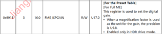
#define IMX728_FME_ISP_GAIN_FID0_ADDR (0xBF04U)

why the isp gain control use the 0xBF04 not use the 0x9918

we find the data sheet use the 0x9918 to control the isp gain.
Thanks a lot.

YL

  • Hi YL,

    Please don't not share any confidential information on public forum.

    we find the exposure has blink, when the sensor gain have changing.

    Could you please provide some more details?

    how to produce the gain table such as imx728_gain_table.h.

    The table is basically for converting linear gain value from AE to IMX728 sensor register format (typically in dB format).

  • Hi, Gang,

    The table is basically for converting linear gain value from AE to IMX728 sensor register format (typically in dB format).

    So, Does I needs to find the converting gain table myself?

    If yes, how do I to find this, is it any method to measure linear gain table?

    If no, where do I find this table, does it provide by Sony?

    Thanks,

    YL

  • Hi YL,

    So, Does I needs to find the converting gain table myself?

    There is a sample gain table for IMX728 in SDK code base.

    https://git.ti.com/cgit/processor-sdk/imaging/tree/sensor_drv/src/imx728/imx728_gain_table.h?h=main

    The 1st column is the linear gain value output from AE.
    The 2nd is the corresponding Sony sensor register value.

    If no, where do I find this table, does it provide by Sony?

    Sony would definitely be able to help you with any questions about the sensor gain values.
    They helped us creating the table in the above link.

  • Hi, Gang,

    Thanks your reply.

    Another question, what do I know the linear gain value from platform corresponding to the sensor db value.

    For a example, 1036 is 0.1 db, 1136 is 0.9 db, which setting on FME_ISPGAIN_UNIT is 0.1 db base.

    static const uint32_t gIMX728GainsTable[ISS_IMX728_GAIN_TBL_SIZE][2U] =
    {
        {1024, 0x0}, \
        {1036, 0x1}, \
        {1048, 0x2}, \
        {1060, 0x3}, \
        {1072, 0x4}, \
        {1085, 0x5}, \
        {1097, 0x6}, \
        {1110, 0x7}, \
        {1123, 0x8}, \
        {1136, 0x9}, \
        {1149, 0xA}, \

    Thanks,

    YL

  • For a example, 1036 is 0.1 db, 1136 is 0.9 db, which setting on FME_ISPGAIN_UNIT is 0.1 db base.

    Yes, that is correct.

    Another question, what do I know the linear gain value from platform corresponding to the sensor db value.

    What is your question?

  • Hi, Gang,

    I means how to I know 1036 is respect to 0.1 db.

    How's 1036 to calculate on TI platform definition.

    Thanks,

    YL

  • Hi YL,

    How's 1036 to calculate on TI platform definition.

    For the 1st column of this table, 1024 is 1.0x gain and everything else is linearly scaled from 1024, i.e., 1036 is 1.0117x gain.

    That relationship is also reflected in AE settings of your sensor.
    You may take a look at the link below.

    https://e2e.ti.com/support/processors-group/processors/f/processors-forum/1262114/faq-setting-up-auto-exposure-ae-for-your-image-sensor-with-tda4-am6xa-isp-vpac

  • Hi, Gang,

    Thanks your clarify explanation.

    Another a question, that make me confused.

    In iss_sensors.h on imaging\sensor_drv\include.

    /**
     *  \brief Sensor Specific Auto Exposure Dynamic Parameters
     * \ingroup group_vision_function_imaging_sensordrv
     */
    typedef struct {
        IssAeRange exposureTimeRange[MAX_AE_DYN_PARAMS];
        /**< range of exposure time in nanoseconds */
        IssAeRange analogGainRange[MAX_AE_DYN_PARAMS];
        /**< range of sensor gain, 1024 = 1x */
        IssAeRange digitalGainRange[MAX_AE_DYN_PARAMS];
        /**< range of ISP Digital gain, 256 = 1x */
        uint32_t                     numAeDynParams;
        /**< Number of Valid Entries in above arrays */
        IssAeRange targetBrightnessRange;
        /**< range of target brightness */
        uint32_t                     targetBrightness;
        /**< target brightness value */
        uint32_t                     threshold;
        /**< threshold for not using history brightness information */
        uint32_t                     exposureTimeStepSize;
        /**< step size of exposure time adjustment */
        uint32_t                     enableBlc;
        /**< TRUE enables Backlight compensation, disabled otherwise */
    } IssAeDynamicPara

    Could you help to confirm which exposure time unit does correct?

    In define of exposureTimeRange, the unit annotation is nanoseconds.

    IssAeRange exposureTimeRange[MAX_AE_DYN_PARAMS];
    /**< range of exposure time in nanoseconds */

    But I see the FAQ on https://e2e.ti.com/support/processors-group/processors/f/processors-forum/1262114/faq-setting-up-auto-exposure-ae-for-your-image-sensor-with-tda4-am6xa-isp-vpac

    The exposureTimeRange unit is microseconds.

    Note: the exposureTimeRange use nanoseconds in iss_sensor_imx728.c on imaging\sensor_drv\src\imx728

    static int32_t IMX728_GetExpPrgFxn(uint32_t chId,
                                        void *pSensorHdl,
                                        IssAeDynamicParams *p_ae_dynPrms)
    {
        int32_t status = 0;
        uint8_t count = 0;
    
        p_ae_dynPrms->targetBrightnessRange.min = 40;
        p_ae_dynPrms->targetBrightnessRange.max = 50;
        p_ae_dynPrms->targetBrightness = 45;
        p_ae_dynPrms->threshold = 1;
        p_ae_dynPrms->enableBlc = 1;
    
        p_ae_dynPrms->exposureTimeStepSize         = 1000000;  // nsec
        p_ae_dynPrms->exposureTimeRange[count].min = 10000000; // nsec
        p_ae_dynPrms->exposureTimeRange[count].max = 10000000; // nsec
        p_ae_dynPrms->analogGainRange[count].min   = 1024;
        p_ae_dynPrms->analogGainRange[count].max   = 16229;
        p_ae_dynPrms->digitalGainRange[count].min  = 256;
        p_ae_dynPrms->digitalGainRange[count].max  = 256;
        count++;
    
        p_ae_dynPrms->numAeDynParams = count;
        return (status);
    }

    Thanks,

    YL

  • Hi YL,

    Could you help to confirm which exposure time unit does correct?

    As a convention we typically to use "us" (microsenconds) for AE settings.
    But, there is no unit in the source code (just number).
    So as long as the AE settings and the sensor driver are aligned, using ns (or anything else) is fine too.