AM625: Ethernet switch connection to RGMII 2

Part Number: AM625

Tool/software:

Hello,

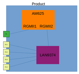
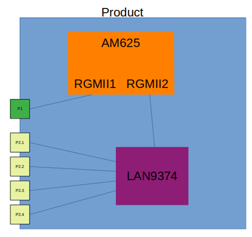
I am trying to to connect an Ethernet switch to the RGMII2 interface on the AM625. The switch in question is a Microchip LAN8374.

The issue I'm having is with being able to connect the switch RGMII port to the AM625's RGMII2 interface- specifically, I cannot link the `ethernet` property of the port node to the cpsw_port2 node as it causes the switch initialisation to fail (ultimately because it cannot find the master node). I can successfully initialise the switch if I connect it to the cpsw3g node, but this seems to connect it to the RGMII1 interface rather than RGMII2.

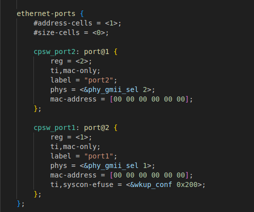
My device tree configuration for the CPSW peripherals is as follows:

&cpsw3g {
	bootph-all;
	pinctrl-names = "default";
	status = "okay";
	pinctrl-0 = <&ethernettx_pins_default>, <&ethernett1internalswitch_pins_default>;

	fixed-link {
		speed = <1000>;
		full-duplex;
	};
};

/* TX Ethernet */
&cpsw_port1 {
	bootph-all;
	phy-mode = "rmii";
	phy-handle = <&cpsw3g_phy0>;
	//ti,dual-emac-pvid = <1>;
	status = "okay";
};

/* T1 Ethernet Switch */
&cpsw_port2 {
	//phy-mode = "rgmii-id";
	phy-mode = "rgmii";
	#address-cells = <1>;
	#size-cells = <0>;
	//ti,dual-emac-pvid = <2>;
	status = "okay";
	
	fixed-link {
		speed = <1000>;
		full-duplex;
	};
};

/* Ethernet MDIO */
&cpsw3g_mdio {
	bootph-all;
	status = "okay";
	pinctrl-names = "default";
	pinctrl-0 = <&ethernetmdio_pins_default>;

	cpsw3g_phy0: ethernet-phy@7 {
		bootph-all;
		reg = <7>;
		rx-internal-delay-ps = <1>;
        tx-internal-delay-ps = <1>;
	};
};

And my switch configuration is:

lan9374: switch@0 {
	compatible = "microchip,lan9374";
	reg = <0>;
	spi-max-frequency = <44000000>;
	power-supply = <&p1v1>;
	phy-mode = "rgmii-id";
	status = "okay";

	mdio {
		#address-cells = <1>;
		#size-cells = <0>;

		t1phy2a: ethernet-phy@0{
				reg = <0x0>;
		};

		t1phy2b: ethernet-phy@1{
				reg = <0x1>;
		};

		t1phy2d: ethernet-phy@2{
				reg = <0x2>;
		};

		t1phy2f: ethernet-phy@3{
				reg = <0x3>;
		};

		t1phy2e: ethernet-phy@6{
				reg = <0x6>;
		};

		t1phy2c: ethernet-phy@7{
				reg = <0x7>;
		};
	};

	ethernet-ports {
		#address-cells = <1>;
		#size-cells = <0>;

		port@0 {
				reg = <0>;
				label = "t1port2a";
				phy-mode = "internal";
				phy-handle = <&t1phy2a>;
		};

		port@1 {
				reg = <1>;
				label = "t1port2b";
				phy-mode = "internal";
				phy-handle = <&t1phy2b>;
		};

		port@2 {
				reg = <2>;
				label = "t1port2d";
				phy-mode = "internal";
				phy-handle = <&t1phy2d>;
		};

		port@3 {
				reg = <3>;
				label = "t1port2f";
				phy-mode = "internal";
				phy-handle = <&t1phy2f>;
		};

		port@4 {
				reg = <4>;
				label = "othermicro";
				phy-mode = "rmii";
				tx-internal-delay-ps = <2000>;
				rx-internal-delay-ps = <2000>;								

				fixed-link {
						speed = <100>;
						full-duplex;
				};
		};

		/* Link to AM625 */
		port@5 {
				reg = <5>;
				label = "cpu";
				phy-mode = "rgmii-id";
				tx-internal-delay-ps = <2000>;
				rx-internal-delay-ps = <2000>;
				//ethernet = <&cpsw_port2>;
				ethernet = <&cpsw3g>;

				fixed-link {
						speed = <1000>;
						full-duplex;
				};
		};

		port@6 {
				reg = <6>;
				label = "t1port2e";
				phy-mode = "internal";
				phy-handle = <&t1phy2e>;
		};

		port@7 {
				reg = <7>;
				label = "t1port2c";
				phy-mode = "internal";
				phy-handle = <&t1phy2c>;
		};
	};		
};

Can you advise how DSA switches are supposed to be connected to RGMII2 please?

Thanks,
Ben

  • Hello Ben, 

    Please note that TI is not able to support external switches and we would not be the right contacts to give guidance on how to integrate your Microchip Ethernet switch. We simply do not have the means to either review or test since there are not any TI EVMs with external switches. Moreover, Microchip is an external vendor and we cannot offer advice on integrating Microchip's parts.

    That being said, we have had customers successfully be able to integrate external switches before. For instance, the following device tree from another customer might be a guide for how you should format your device tree to integrate an external switch: https://e2e.ti.com/support/processors-group/processors/f/processors-forum/1159207/am6442-issues-with-dsa-switch-at-cpsw3g-port/4379028#4379028

    Please let us know if you have follow-up questions.

    -Daolin

  • Hello Daolin,

    The issue I'm having is not with the Microchip Ethernet switch (which appears to be working fine) specifically, but with how to connect any internal Ethernet switch to the RGMII 2 port given that TI decided to implement the two Ethernet interfaces as a switch, rather than two dedicated interfaces. This seems to be made a lot more difficult by the CPSW not supporting a proper DSA tag protocol, but relying on 802.1q VLAN identifiers (which, per the documentation - kernel.org/doc/Documentation/networking/dsa/dsa.txt - is identified as having limitations) to determine the source and destination port (this, in my opinion, is a poor design choice). I would suggest that connecting an internal switch to the AM625 RGMII 2 port is a perfectly valid use case, so I would appreciate some support in how to go about this.

    Do TI have a reference for how this should be implemented? My requirement is that each port of the switch can operate in a distinct VLAN, but I'm not sure how that aligns when connecting to CPSW which will add/remove VLAN tags on ingress/egress. Can DSA switch trees be used to support this? If so, can you provide any details on how the CPSW is set up in terms of switch trees? Or if this isn't the correct way to go about this, can I alter the behavior of how CPSW adds/removes VLAN tags? I understand that the CPSW can be operated in switch mode (which I believe disables the VLANing?) but I'm not clear on how to enable that in the device tree. And if I did enable it, is it still possible to ensure that RGMII 1 and RGMII 2 remain separate with no cross-contamination of traffic?

    Thanks,
    Ben

  • Hi Ben, 

    I think I may have not explained properly in my last response. What I meant was that we don't have any specific examples of how to connect any Ethernet switch directly to our CPSW ports. I understand that connecting a switch to a CPSW RGMII port is a valid use case but unfortunately what I was trying to explain is that we currently don't have any TI specific examples/references, only examples of other customer use cases successfully bringing up a switch connection. 

    That being said, we have had customers successfully be able to integrate external switches before. For instance, the following device tree from another customer might be a guide for how you should format your device tree to integrate an external switch: https://e2e.ti.com/support/processors-group/processors/f/processors-forum/1159207/am6442-issues-with-dsa-switch-at-cpsw3g-port/4379028#4379028

    May I ask, does this reference give some guidance?

    >>>The issue I'm having is not with the Microchip Ethernet switch (which appears to be working fine) specifically, but with how to connect any internal Ethernet switch to the RGMII 2 port given that TI decided to implement the two Ethernet interfaces as a switch, rather than two dedicated interfaces

    Can you explain what you mean by "internal switch"? Is this "internal switch" you are referring to not the Microchip Ethernet switch?

    -Daolin

  • Hi Ben,

    Did you get it working? we are also using the same switch in our system. i have added the LAN9374 under SPI and for us we are able to get the LAN9374 detected message in the boot logs but still we get deferred probing and No LAN ports are also added under ifconfig.

    Have a look at this ticket:

    e2e.ti.com/.../am625-ethernet-switch-with-am625

  • Hi Ben,

    Did LAN9374 work for you?

  • Hello Daolin,

    Apologies for my late response; I've had to work on some other priorities for the last few weeks.

    Yes, the "internal switch" is the Microchip LAN9374. Our setup is as follows:

    Because cpsw_port1 and cpsw_port2 aren't MACs, all I can do is bind the LAN9374 CPU port to the root cpsw3g node. In dsa.c, a call is made to of_find_net_device_by_node() to find the upstream MAC for the switch CPU port; this ultimately uses class_find_device(), which finds the first node of the correct class and stops. This means that my LAN9374 switch ends up "logically" connected to RGMII1 rather than RGMII2, which isn't correct. I've tried getting around this with a quick hack to make it use the second matching node rather than the first; in this case, the switch ends up logically descending from RGMII2 as expected, but doesn't work (i.e. doesn't pass traffic).

    The only difference I can see in the device tree you linked to is the use of the dsa,member property. This makes sense given that my LAN9374 is effectively the second switch in the tree, with the AM625 being the root switch, but I don't understand why its value is set to 0 0. Would you expect this?

    Would you be able to advise on how to correctly set this up please? Per the diagram, product port P1 is a single TX phy (TI DP83826) connected to RGMII1 (as RMII). P2.1-P2.4 are T1 ports connected to a LAN9374 switch, in turn connected to RGMII2. P1 will not use 802.1q VLANs, but I need P2.1-P2.4 to be able to sit in different VLANs.

    Kind regards,
    Ben

  • Hello Naveenkumar,

    No, our switch is still not working unfortunately, though it does probe successfully. Are your drivers set up as built-in, or modules? If the latter, are they all loaded? If the probe is deferred, it often means that not all elements of the driver chain aren't loaded yet (i.e. both the switch drivers, relevant kernel modules for the DSA subsystem, and the SPI peripheral drivers).

    Thanks,
    Ben

  • hi Ben,

    My drivers are  added as module itself, and in my kernel version is 6.1.80 in which i have option only to load as module.

    for LAN9374, i have to use cpsw3g as ethetnet port, if i use cpsw_port2 it does work

  • Hi Ben, 

    The only difference I can see in the device tree you linked to is the use of the dsa,member property. This makes sense given that my LAN9374 is effectively the second switch in the tree, with the AM625 being the root switch, but I don't understand why its value is set to 0 0. Would you expect this?

    This dsa,member property appears to be more of a switch configuration property rather than CPSW property. In the referenced device tree, the customer added the dsa,member property to the switch node that they were using so I cannot comment on why they chose to set 0 0. Since the switch you are using is not a TI part, I cannot offer any official comments on this dsa,member property. That being said, would the description in https://www.kernel.org/doc/Documentation/devicetree/bindings/net/dsa/dsa.yaml help explain the dsa,member property?

    Would you be able to advise on how to correctly set this up please? Per the diagram, product port P1 is a single TX phy (TI DP83826) connected to RGMII1 (as RMII). P2.1-P2.4 are T1 ports connected to a LAN9374 switch, in turn connected to RGMII2. P1 will not use 802.1q VLANs, but I need P2.1-P2.4 to be able to sit in different VLANs.
    In dsa.c, a call is made to of_find_net_device_by_node() to find the upstream MAC for the switch CPU port; this ultimately uses class_find_device(), which finds the first node of the correct class and stops. This means that my LAN9374 switch ends up "logically" connected to RGMII1 rather than RGMII2, which isn't correct.

    Let us focus first on why the switch is not logically connected to RGMII2 first, it appears to be a similar behavior to Naveenkumar's thread. I need some time to discuss internally about this issue. I plan to respond with an update Wednesday, please kindly ping this thread if you don't hear a response by then.

    -Daolin

  • hi ben,

    did it work for you? after patching the driver with changes also i don't have any communication.

  • HI Ben, 

    Can you share your decompiled DTS (i.e. decompiled from DTB)?

    -Daolin

  • Hello Daolin,

    Sorry for my late reply to this; unfortunately I've had to work on other priorities, but am able to focus on this again now.

    Please find attached 

    /dts-v1/;
    
    / {
    	compatible = "ti,am625";
    	interrupt-parent = <0x01>;
    	#address-cells = <0x02>;
    	#size-cells = <0x02>;
    
    	chosen {
    		stdout-path = "serial2:115200n8";
    	};
    
    	firmware {
    
    		optee {
    			compatible = "linaro,optee-tz";
    			method = "smc";
    		};
    
    		psci {
    			compatible = "arm,psci-1.0";
    			method = "smc";
    			phandle = <0x58>;
    		};
    	};
    
    	timer-cl0-cpu0 {
    		compatible = "arm,armv8-timer";
    		interrupts = <0x01 0x0d 0x08 0x01 0x0e 0x08 0x01 0x0b 0x08 0x01 0x0a 0x08>;
    		phandle = <0x59>;
    	};
    
    	pmu {
    		compatible = "arm,cortex-a53-pmu";
    		interrupts = <0x01 0x07 0x04>;
    		phandle = <0x5a>;
    	};
    
    	bus@f0000 {
    		bootph-all;
    		compatible = "simple-bus";
    		#address-cells = <0x02>;
    		#size-cells = <0x02>;
    		ranges = <0x00 0xf0000 0x00 0xf0000 0x00 0x30000 0x00 0x420000 0x00 0x420000 0x00 0x1000 0x00 0x600000 0x00 0x600000 0x00 0x1100 0x00 0x703000 0x00 0x703000 0x00 0x200 0x00 0x70c000 0x00 0x70c000 0x00 0x200 0x00 0xa40000 0x00 0xa40000 0x00 0x800 0x00 0x1000000 0x00 0x1000000 0x00 0x1b28400 0x00 0x8000000 0x00 0x8000000 0x00 0x200000 0x00 0xe000000 0x00 0xe000000 0x00 0x1d20000 0x00 0xfd00000 0x00 0xfd00000 0x00 0x20000 0x00 0x20000000 0x00 0x20000000 0x00 0xa008000 0x00 0x30040000 0x00 0x30040000 0x00 0x80000 0x00 0x30101000 0x00 0x30101000 0x00 0x10100 0x00 0x30200000 0x00 0x30200000 0x00 0x10000 0x00 0x30300000 0x00 0x30300000 0x00 0x1000 0x00 0x31000000 0x00 0x31000000 0x00 0x50000 0x00 0x31100000 0x00 0x31100000 0x00 0x50000 0x00 0x3b000000 0x00 0x3b000000 0x00 0x400 0x00 0x40900000 0x00 0x40900000 0x00 0x30000 0x00 0x43600000 0x00 0x43600000 0x00 0x10000 0x00 0x44043000 0x00 0x44043000 0x00 0xfe0 0x00 0x44860000 0x00 0x44860000 0x00 0x40000 0x00 0x48000000 0x00 0x48000000 0x00 0x6400000 0x00 0x50000000 0x00 0x50000000 0x00 0x8000000 0x00 0x60000000 0x00 0x60000000 0x00 0x8000000 0x00 0x70000000 0x00 0x70000000 0x00 0x10000 0x01 0x00 0x01 0x00 0x00 0x310000 0x05 0x00 0x05 0x00 0x01 0x00 0x00 0x4000000 0x00 0x4000000 0x00 0x1ff1400 0x00 0xb00000 0x00 0xb00000 0x00 0x2400 0x00 0x2b000000 0x00 0x2b000000 0x00 0x300400 0x00 0x43000000 0x00 0x43000000 0x00 0x20000 0x00 0x78000000 0x00 0x78000000 0x00 0x8000 0x00 0x78100000 0x00 0x78100000 0x00 0x8000>;
    		phandle = <0x5b>;
    
    		bus@4000000 {
    			bootph-all;
    			compatible = "simple-bus";
    			#address-cells = <0x02>;
    			#size-cells = <0x02>;
    			ranges = <0x00 0x4000000 0x00 0x4000000 0x00 0x1ff1400>;
    			phandle = <0x5c>;
    
    			pinctrl@4084000 {
    				bootph-all;
    				compatible = "pinctrl-single";
    				reg = <0x00 0x4084000 0x00 0x88>;
    				#pinctrl-cells = <0x01>;
    				pinctrl-single,register-width = <0x20>;
    				pinctrl-single,function-mask = <0xffffffff>;
    				phandle = <0x5d>;
    
    				jtag-default-pins {
    					pinctrl-single,pins = <0x78 0x60000 0x7c 0x60000 0x64 0x60000 0x6c 0x60000 0x70 0x20000 0x74 0x60000 0x68 0x40000>;
    					phandle = <0x5e>;
    				};
    
    				can2-default-pins {
    					pinctrl-single,pins = <0x38 0x50000 0x34 0x10000>;
    					phandle = <0x06>;
    				};
    
    				can3-default-pins {
    					pinctrl-single,pins = <0x40 0x50000 0x3c 0x10000>;
    					phandle = <0x07>;
    				};
    
    				mcusystem-default-pins {
    					pinctrl-single,pins = <0x60 0x40000 0x58 0x50000 0x5c 0x10000 0x54 0x60000>;
    					phandle = <0x5f>;
    				};
    
    				mcuconsole-default-pins {
    					pinctrl-single,pins = <0x1c 0x50000 0x20 0x10000 0x14 0x50000 0x18 0x10000>;
    					phandle = <0x60>;
    				};
    
    				wakeupi2c-default-pins {
    					pinctrl-single,pins = <0x4c 0x50000 0x50 0x50000>;
    					phandle = <0x61>;
    				};
    
    				wakeupsystem-default-pins {
    					pinctrl-single,pins = <0x84 0x10000 0x80 0x10000>;
    					phandle = <0x62>;
    				};
    
    				wakeuptimer-default-pins {
    					pinctrl-single,pins = <0x00 0x50004>;
    					phandle = <0x63>;
    				};
    
    				wakeupuart-default-pins {
    					bootph-pre-ram;
    					pinctrl-single,pins = <0x2c 0x50000 0x30 0x10000 0x24 0x50000 0x28 0x10000>;
    					phandle = <0x0d>;
    				};
    			};
    
    			esm@4100000 {
    				bootph-pre-ram;
    				compatible = "ti,j721e-esm";
    				reg = <0x00 0x4100000 0x00 0x1000>;
    				ti,esm-pins = <0x00 0x01 0x02 0x55>;
    				phandle = <0x64>;
    			};
    
    			timer@4800000 {
    				compatible = "ti,am654-timer";
    				reg = <0x00 0x4800000 0x00 0x400>;
    				clocks = <0x02 0x23 0x02>;
    				clock-names = "fck";
    				power-domains = <0x03 0x23 0x01>;
    				ti,timer-pwm;
    				status = "reserved";
    				phandle = <0x65>;
    			};
    
    			timer@4810000 {
    				compatible = "ti,am654-timer";
    				reg = <0x00 0x4810000 0x00 0x400>;
    				clocks = <0x02 0x30 0x02>;
    				clock-names = "fck";
    				power-domains = <0x03 0x30 0x01>;
    				ti,timer-pwm;
    				status = "reserved";
    				phandle = <0x66>;
    			};
    
    			timer@4820000 {
    				compatible = "ti,am654-timer";
    				reg = <0x00 0x4820000 0x00 0x400>;
    				clocks = <0x02 0x31 0x02>;
    				clock-names = "fck";
    				power-domains = <0x03 0x31 0x01>;
    				ti,timer-pwm;
    				status = "reserved";
    				phandle = <0x67>;
    			};
    
    			timer@4830000 {
    				compatible = "ti,am654-timer";
    				reg = <0x00 0x4830000 0x00 0x400>;
    				clocks = <0x02 0x32 0x02>;
    				clock-names = "fck";
    				power-domains = <0x03 0x32 0x01>;
    				ti,timer-pwm;
    				status = "reserved";
    				phandle = <0x68>;
    			};
    
    			serial@4a00000 {
    				compatible = "ti,am64-uart\0ti,am654-uart";
    				reg = <0x00 0x4a00000 0x00 0x100>;
    				interrupts = <0x00 0xb9 0x04>;
    				power-domains = <0x03 0x95 0x01>;
    				clocks = <0x02 0x95 0x00>;
    				clock-names = "fclk";
    				status = "disabled";
    				phandle = <0x14>;
    			};
    
    			i2c@4900000 {
    				compatible = "ti,am64-i2c\0ti,omap4-i2c";
    				reg = <0x00 0x4900000 0x00 0x100>;
    				interrupts = <0x00 0x6b 0x04>;
    				#address-cells = <0x01>;
    				#size-cells = <0x00>;
    				power-domains = <0x03 0x6a 0x01>;
    				clocks = <0x02 0x6a 0x02>;
    				clock-names = "fck";
    				status = "disabled";
    				phandle = <0x69>;
    			};
    
    			spi@4b00000 {
    				compatible = "ti,am654-mcspi\0ti,omap4-mcspi";
    				reg = <0x00 0x4b00000 0x00 0x400>;
    				interrupts = <0x00 0xb0 0x04>;
    				#address-cells = <0x01>;
    				#size-cells = <0x00>;
    				power-domains = <0x03 0x93 0x01>;
    				clocks = <0x02 0x93 0x00>;
    				status = "disabled";
    				phandle = <0x6a>;
    			};
    
    			spi@4b10000 {
    				compatible = "ti,am654-mcspi\0ti,omap4-mcspi";
    				reg = <0x00 0x4b10000 0x00 0x400>;
    				interrupts = <0x00 0xb1 0x04>;
    				#address-cells = <0x01>;
    				#size-cells = <0x00>;
    				power-domains = <0x03 0x94 0x01>;
    				clocks = <0x02 0x94 0x00>;
    				status = "disabled";
    				phandle = <0x6b>;
    			};
    
    			interrupt-controller@4210000 {
    				compatible = "ti,sci-intr";
    				reg = <0x00 0x4210000 0x00 0x200>;
    				ti,intr-trigger-type = <0x01>;
    				interrupt-controller;
    				interrupt-parent = <0x01>;
    				#interrupt-cells = <0x01>;
    				ti,sci = <0x04>;
    				ti,sci-dev-id = <0x05>;
    				ti,interrupt-ranges = <0x00 0x68 0x04>;
    				status = "reserved";
    				phandle = <0x05>;
    			};
    
    			gpio@4201000 {
    				compatible = "ti,am64-gpio\0ti,keystone-gpio";
    				reg = <0x00 0x4201000 0x00 0x100>;
    				gpio-controller;
    				#gpio-cells = <0x02>;
    				interrupt-parent = <0x05>;
    				interrupts = <0x1e 0x1f>;
    				interrupt-controller;
    				#interrupt-cells = <0x02>;
    				ti,ngpio = <0x18>;
    				ti,davinci-gpio-unbanked = <0x00>;
    				power-domains = <0x03 0x4f 0x01>;
    				clocks = <0x02 0x4f 0x00>;
    				clock-names = "gpio";
    				status = "reserved";
    				phandle = <0x6c>;
    			};
    
    			watchdog@4880000 {
    				compatible = "ti,j7-rti-wdt";
    				reg = <0x00 0x4880000 0x00 0x100>;
    				clocks = <0x02 0x83 0x00>;
    				power-domains = <0x03 0x83 0x01>;
    				assigned-clocks = <0x02 0x83 0x00>;
    				assigned-clock-parents = <0x02 0x83 0x02>;
    				status = "reserved";
    				phandle = <0x6d>;
    			};
    
    			can@4e08000 {
    				compatible = "bosch,m_can";
    				reg = <0x00 0x4e08000 0x00 0x200 0x00 0x4e00000 0x00 0x8000>;
    				reg-names = "m_can\0message_ram";
    				power-domains = <0x03 0xbc 0x01>;
    				clocks = <0x02 0xbc 0x06 0x02 0xbc 0x01>;
    				clock-names = "hclk\0cclk";
    				bosch,mram-cfg = <0x00 0x80 0x40 0x40 0x40 0x40 0x20 0x20>;
    				wakeup-source;
    				status = "okay";
    				pinctrl-names = "default";
    				pinctrl-0 = <0x06>;
    				phandle = <0x12>;
    			};
    
    			can@4e18000 {
    				compatible = "bosch,m_can";
    				reg = <0x00 0x4e18000 0x00 0x200 0x00 0x4e10000 0x00 0x8000>;
    				reg-names = "m_can\0message_ram";
    				power-domains = <0x03 0xbd 0x01>;
    				clocks = <0x02 0xbd 0x06 0x02 0xbd 0x01>;
    				clock-names = "hclk\0cclk";
    				bosch,mram-cfg = <0x00 0x80 0x40 0x40 0x40 0x40 0x20 0x20>;
    				wakeup-source;
    				status = "okay";
    				pinctrl-names = "default";
    				pinctrl-0 = <0x07>;
    				phandle = <0x13>;
    			};
    
    			m4fss@5000000 {
    				compatible = "ti,am64-m4fss";
    				reg = <0x00 0x5000000 0x00 0x30000 0x00 0x5040000 0x00 0x10000>;
    				reg-names = "iram\0dram";
    				resets = <0x08 0x09 0x01>;
    				firmware-name = "am62-mcu-m4f0_0-fw";
    				ti,sci = <0x04>;
    				ti,sci-dev-id = <0x09>;
    				ti,sci-proc-ids = <0x18 0xff>;
    				status = "okay";
    				mboxes = <0x09 0x0a>;
    				memory-region = <0x0b 0x0c>;
    				phandle = <0x6e>;
    			};
    		};
    
    		bus@b00000 {
    			bootph-all;
    			compatible = "simple-bus";
    			#address-cells = <0x02>;
    			#size-cells = <0x02>;
    			ranges = <0x00 0xb00000 0x00 0xb00000 0x00 0x2400 0x00 0x2b000000 0x00 0x2b000000 0x00 0x300400 0x00 0x43000000 0x00 0x43000000 0x00 0x20000 0x00 0x78000000 0x00 0x78000000 0x00 0x8000 0x00 0x78100000 0x00 0x78100000 0x00 0x8000>;
    			phandle = <0x6f>;
    
    			syscon@43000000 {
    				bootph-all;
    				compatible = "syscon\0simple-mfd";
    				reg = <0x00 0x43000000 0x00 0x20000>;
    				#address-cells = <0x01>;
    				#size-cells = <0x01>;
    				ranges = <0x00 0x00 0x43000000 0x20000>;
    				phandle = <0x37>;
    
    				chipid@14 {
    					bootph-all;
    					compatible = "ti,am654-chipid";
    					reg = <0x14 0x04>;
    					phandle = <0x70>;
    				};
    
    				syscon@4008 {
    					compatible = "ti,am62-usb-phy-ctrl\0syscon";
    					reg = <0x4008 0x04>;
    					phandle = <0x30>;
    				};
    
    				syscon@4018 {
    					compatible = "ti,am62-usb-phy-ctrl\0syscon";
    					reg = <0x4018 0x04>;
    					phandle = <0x32>;
    				};
    			};
    
    			target-module@2b300050 {
    				compatible = "ti,sysc-omap2\0ti,sysc";
    				reg = <0x00 0x2b300050 0x00 0x04 0x00 0x2b300054 0x00 0x04 0x00 0x2b300058 0x00 0x04>;
    				reg-names = "rev\0sysc\0syss";
    				ti,sysc-mask = <0x07>;
    				ti,sysc-sidle = <0x00 0x01 0x02 0x03>;
    				ti,syss-mask = <0x01>;
    				ti,no-reset-on-init;
    				power-domains = <0x03 0x72 0x01>;
    				clocks = <0x02 0x72 0x00>;
    				clock-names = "fck";
    				#address-cells = <0x01>;
    				#size-cells = <0x01>;
    				ranges = <0x00 0x00 0x2b300000 0x100000>;
    
    				serial@0 {
    					compatible = "ti,am64-uart\0ti,am654-uart";
    					reg = <0x00 0x100>;
    					interrupts = <0x00 0xba 0x04>;
    					status = "reserved";
    					bootph-pre-ram;
    					pinctrl-names = "default";
    					pinctrl-0 = <0x0d>;
    					phandle = <0x15>;
    				};
    			};
    
    			i2c@2b200000 {
    				compatible = "ti,am64-i2c\0ti,omap4-i2c";
    				reg = <0x00 0x2b200000 0x00 0x100>;
    				interrupts = <0x00 0xa5 0x04>;
    				#address-cells = <0x01>;
    				#size-cells = <0x00>;
    				power-domains = <0x03 0x6b 0x01>;
    				clocks = <0x02 0x6b 0x04>;
    				clock-names = "fck";
    				status = "disabled";
    				phandle = <0x71>;
    			};
    
    			rtc@2b1f0000 {
    				compatible = "ti,am62-rtc";
    				reg = <0x00 0x2b1f0000 0x00 0x100>;
    				interrupts = <0x00 0x64 0x04>;
    				clocks = <0x02 0x75 0x06 0x02 0x75 0x00>;
    				clock-names = "vbus\0osc32k";
    				power-domains = <0x03 0x75 0x01>;
    				wakeup-source;
    				phandle = <0x72>;
    			};
    
    			watchdog@2b000000 {
    				compatible = "ti,j7-rti-wdt";
    				reg = <0x00 0x2b000000 0x00 0x100>;
    				clocks = <0x02 0x84 0x00>;
    				power-domains = <0x03 0x84 0x01>;
    				assigned-clocks = <0x02 0x84 0x00>;
    				assigned-clock-parents = <0x02 0x84 0x02>;
    				status = "reserved";
    				phandle = <0x73>;
    			};
    
    			r5fss@78000000 {
    				compatible = "ti,am62-r5fss";
    				#address-cells = <0x01>;
    				#size-cells = <0x01>;
    				ranges = <0x78000000 0x00 0x78000000 0x8000 0x78100000 0x00 0x78100000 0x8000>;
    				power-domains = <0x03 0x77 0x01>;
    				phandle = <0x74>;
    
    				r5f@78000000 {
    					compatible = "ti,am62-r5f";
    					reg = <0x78000000 0x8000 0x78100000 0x8000>;
    					reg-names = "atcm\0btcm";
    					ti,sci = <0x04>;
    					ti,sci-dev-id = <0x79>;
    					ti,sci-proc-ids = <0x01 0xff>;
    					resets = <0x08 0x79 0x01>;
    					firmware-name = "ti-sysfw/ti-fs-stub-firmware-am62x-gp-signed.bin";
    					ti,atcm-enable = <0x01>;
    					ti,btcm-enable = <0x01>;
    					ti,loczrama = <0x01>;
    					phandle = <0x75>;
    				};
    			};
    
    			temperature-sensor@b00000 {
    				compatible = "ti,j7200-vtm";
    				reg = <0x00 0xb00000 0x00 0x400 0x00 0xb01000 0x00 0x400>;
    				power-domains = <0x03 0x5f 0x01>;
    				#thermal-sensor-cells = <0x01>;
    				phandle = <0x49>;
    			};
    		};
    
    		sram@70000000 {
    			compatible = "mmio-sram";
    			reg = <0x00 0x70000000 0x00 0x10000>;
    			#address-cells = <0x01>;
    			#size-cells = <0x01>;
    			ranges = <0x00 0x00 0x70000000 0x10000>;
    			phandle = <0x76>;
    		};
    
    		interrupt-controller@1800000 {
    			compatible = "arm,gic-v3";
    			#address-cells = <0x02>;
    			#size-cells = <0x02>;
    			ranges;
    			#interrupt-cells = <0x03>;
    			interrupt-controller;
    			reg = <0x00 0x1800000 0x00 0x10000 0x00 0x1880000 0x00 0xc0000 0x00 0x1880000 0x00 0xc0000 0x01 0x00 0x00 0x2000 0x01 0x10000 0x00 0x1000 0x01 0x20000 0x00 0x2000>;
    			interrupts = <0x01 0x09 0x04>;
    			phandle = <0x01>;
    
    			msi-controller@1820000 {
    				compatible = "arm,gic-v3-its";
    				reg = <0x00 0x1820000 0x00 0x10000>;
    				socionext,synquacer-pre-its = <0x1000000 0x400000>;
    				msi-controller;
    				#msi-cells = <0x01>;
    				phandle = <0x77>;
    			};
    		};
    
    		bus@100000 {
    			compatible = "simple-bus";
    			#address-cells = <0x01>;
    			#size-cells = <0x01>;
    			ranges = <0x00 0x00 0x100000 0x20000>;
    			phandle = <0x78>;
    
    			phy@4044 {
    				compatible = "ti,am654-phy-gmii-sel";
    				reg = <0x4044 0x08>;
    				#phy-cells = <0x01>;
    				phandle = <0x36>;
    			};
    
    			clock-controller@4130 {
    				compatible = "ti,am62-epwm-tbclk";
    				reg = <0x4130 0x04>;
    				#clock-cells = <0x01>;
    				phandle = <0x42>;
    			};
    
    			clock-controller@82e0 {
    				compatible = "ti,am62-audio-refclk";
    				reg = <0x82e0 0x04>;
    				clocks = <0x02 0x9d 0x00>;
    				assigned-clocks = <0x02 0x9d 0x00>;
    				assigned-clock-parents = <0x02 0x9d 0x08>;
    				#clock-cells = <0x00>;
    				phandle = <0x79>;
    			};
    
    			clock-controller@82e4 {
    				compatible = "ti,am62-audio-refclk";
    				reg = <0x82e4 0x04>;
    				clocks = <0x02 0x9d 0x0a>;
    				assigned-clocks = <0x02 0x9d 0x0a>;
    				assigned-clock-parents = <0x02 0x9d 0x12>;
    				#clock-cells = <0x00>;
    				phandle = <0x7a>;
    			};
    
    			oldi-io-controller@8600 {
    				compatible = "ti,am625-dss-oldi-io-ctrl\0syscon";
    				reg = <0x8600 0x200>;
    				bootph-all;
    				phandle = <0x3d>;
    			};
    		};
    
    		bus@48000000 {
    			bootph-all;
    			compatible = "simple-bus";
    			#address-cells = <0x02>;
    			#size-cells = <0x02>;
    			dma-ranges;
    			ranges = <0x00 0x48000000 0x00 0x48000000 0x00 0x6400000>;
    			ti,sci-dev-id = <0x19>;
    			phandle = <0x7b>;
    
    			mailbox@4d000000 {
    				bootph-all;
    				compatible = "ti,am654-secure-proxy";
    				#mbox-cells = <0x01>;
    				reg-names = "target_data\0rt\0scfg";
    				reg = <0x00 0x4d000000 0x00 0x80000 0x00 0x4a600000 0x00 0x80000 0x00 0x4a400000 0x00 0x80000>;
    				interrupt-names = "rx_012";
    				interrupts = <0x00 0x22 0x04>;
    				phandle = <0x11>;
    			};
    
    			interrupt-controller@48000000 {
    				compatible = "ti,sci-inta";
    				reg = <0x00 0x48000000 0x00 0x100000>;
    				#interrupt-cells = <0x00>;
    				interrupt-controller;
    				interrupt-parent = <0x01>;
    				msi-controller;
    				ti,sci = <0x04>;
    				ti,sci-dev-id = <0x1c>;
    				ti,interrupt-ranges = <0x04 0x44 0x24>;
    				ti,unmapped-event-sources = <0x0e 0x0f>;
    				phandle = <0x10>;
    			};
    
    			dma-controller@485c0100 {
    				compatible = "ti,am64-dmss-bcdma";
    				reg = <0x00 0x485c0100 0x00 0x100 0x00 0x4c000000 0x00 0x20000 0x00 0x4a820000 0x00 0x20000 0x00 0x4aa40000 0x00 0x20000 0x00 0x4bc00000 0x00 0x100000 0x00 0x48600000 0x00 0x8000 0x00 0x484a4000 0x00 0x2000 0x00 0x484c2000 0x00 0x2000 0x00 0x48420000 0x00 0x2000>;
    				reg-names = "gcfg\0bchanrt\0rchanrt\0tchanrt\0ringrt\0ring\0tchan\0rchan\0bchan";
    				msi-parent = <0x10>;
    				#dma-cells = <0x03>;
    				ti,sci = <0x04>;
    				ti,sci-dev-id = <0x1a>;
    				ti,sci-rm-range-bchan = <0x20>;
    				ti,sci-rm-range-rchan = <0x21>;
    				ti,sci-rm-range-tchan = <0x22>;
    				phandle = <0x0e>;
    			};
    
    			dma-controller@485c0000 {
    				compatible = "ti,am64-dmss-pktdma";
    				reg = <0x00 0x485c0000 0x00 0x100 0x00 0x4a800000 0x00 0x20000 0x00 0x4aa00000 0x00 0x40000 0x00 0x4b800000 0x00 0x400000 0x00 0x485e0000 0x00 0x10000 0x00 0x484a0000 0x00 0x2000 0x00 0x484c0000 0x00 0x2000 0x00 0x48430000 0x00 0x1000>;
    				reg-names = "gcfg\0rchanrt\0tchanrt\0ringrt\0ring\0tchan\0rchan\0rflow";
    				msi-parent = <0x10>;
    				#dma-cells = <0x02>;
    				ti,sci = <0x04>;
    				ti,sci-dev-id = <0x1e>;
    				ti,sci-rm-range-tchan = <0x23 0x24 0x25 0x26>;
    				ti,sci-rm-range-tflow = <0x10 0x11 0x12 0x13>;
    				ti,sci-rm-range-rchan = <0x29 0x2b 0x2d 0x2f 0x31 0x33>;
    				ti,sci-rm-range-rflow = <0x2a 0x2c 0x2e 0x32>;
    				bootph-all;
    				phandle = <0x0f>;
    			};
    		};
    
    		system-controller@44043000 {
    			bootph-all;
    			compatible = "ti,k2g-sci";
    			ti,host-id = <0x0c>;
    			mbox-names = "rx\0tx";
    			mboxes = <0x11 0x0c 0x11 0x0d>;
    			reg-names = "debug_messages";
    			reg = <0x00 0x44043000 0x00 0xfe0>;
    			ti,partial-io-wakeup-sources = <0x12 0x13 0x14 0x15>;
    			phandle = <0x04>;
    
    			power-controller {
    				bootph-all;
    				compatible = "ti,sci-pm-domain";
    				#power-domain-cells = <0x02>;
    				phandle = <0x03>;
    			};
    
    			clock-controller {
    				bootph-all;
    				compatible = "ti,k2g-sci-clk";
    				#clock-cells = <0x02>;
    				phandle = <0x02>;
    			};
    
    			reset-controller {
    				bootph-all;
    				compatible = "ti,sci-reset";
    				#reset-cells = <0x02>;
    				phandle = <0x08>;
    			};
    		};
    
    		crypto@40900000 {
    			compatible = "ti,am62-sa3ul";
    			reg = <0x00 0x40900000 0x00 0x1200>;
    			#address-cells = <0x02>;
    			#size-cells = <0x02>;
    			ranges = <0x00 0x40900000 0x00 0x40900000 0x00 0x30000>;
    			dmas = <0x0f 0xf501 0x00 0x0f 0x7506 0x00 0x0f 0x7507 0x00>;
    			dma-names = "tx\0rx1\0rx2";
    			phandle = <0x7c>;
    		};
    
    		crc@30300000 {
    			compatible = "ti,am62-mcrc64";
    			reg = <0x00 0x30300000 0x00 0x1000>;
    			clocks = <0x02 0x74 0x00>;
    			power-domains = <0x03 0x74 0x01>;
    			phandle = <0x7d>;
    		};
    
    		mailbox@43600000 {
    			bootph-pre-ram;
    			compatible = "ti,am654-secure-proxy";
    			#mbox-cells = <0x01>;
    			reg-names = "target_data\0rt\0scfg";
    			reg = <0x00 0x43600000 0x00 0x10000 0x00 0x44880000 0x00 0x20000 0x00 0x44860000 0x00 0x20000>;
    			status = "disabled";
    			phandle = <0x7e>;
    		};
    
    		pinctrl@f4000 {
    			bootph-all;
    			compatible = "ti,am654-padconf\0pinctrl-single";
    			reg = <0x00 0xf4000 0x00 0x2ac>;
    			#pinctrl-cells = <0x01>;
    			pinctrl-single,register-width = <0x20>;
    			pinctrl-single,function-mask = <0xffffffff>;
    			interrupts = <0x00 0x62 0x04>;
    			interrupt-controller;
    			#interrupt-cells = <0x01>;
    			phandle = <0x17>;
    		};
    
    		esm@420000 {
    			bootph-pre-ram;
    			compatible = "ti,j721e-esm";
    			reg = <0x00 0x420000 0x00 0x1000>;
    			ti,esm-pins = <0xa0 0xa1 0xa2 0xa3 0xb1 0xb2>;
    			phandle = <0x81>;
    		};
    
    		timer@2400000 {
    			bootph-all;
    			compatible = "ti,am654-timer";
    			reg = <0x00 0x2400000 0x00 0x400>;
    			interrupts = <0x00 0x78 0x04>;
    			clocks = <0x02 0x24 0x02>;
    			clock-names = "fck";
    			assigned-clocks = <0x02 0x24 0x02>;
    			assigned-clock-parents = <0x02 0x24 0x03>;
    			power-domains = <0x03 0x24 0x01>;
    			ti,timer-pwm;
    			phandle = <0x82>;
    		};
    
    		timer@2410000 {
    			compatible = "ti,am654-timer";
    			reg = <0x00 0x2410000 0x00 0x400>;
    			interrupts = <0x00 0x79 0x04>;
    			clocks = <0x02 0x25 0x02>;
    			clock-names = "fck";
    			assigned-clocks = <0x02 0x25 0x02>;
    			assigned-clock-parents = <0x02 0x25 0x03>;
    			power-domains = <0x03 0x25 0x01>;
    			ti,timer-pwm;
    			phandle = <0x83>;
    		};
    
    		timer@2420000 {
    			compatible = "ti,am654-timer";
    			reg = <0x00 0x2420000 0x00 0x400>;
    			interrupts = <0x00 0x7a 0x04>;
    			clocks = <0x02 0x26 0x02>;
    			clock-names = "fck";
    			assigned-clocks = <0x02 0x26 0x02>;
    			assigned-clock-parents = <0x02 0x26 0x03>;
    			power-domains = <0x03 0x26 0x01>;
    			ti,timer-pwm;
    			phandle = <0x84>;
    		};
    
    		timer@2430000 {
    			compatible = "ti,am654-timer";
    			reg = <0x00 0x2430000 0x00 0x400>;
    			interrupts = <0x00 0x7b 0x04>;
    			clocks = <0x02 0x27 0x02>;
    			clock-names = "fck";
    			assigned-clocks = <0x02 0x27 0x02>;
    			assigned-clock-parents = <0x02 0x27 0x03>;
    			power-domains = <0x03 0x27 0x01>;
    			ti,timer-pwm;
    			phandle = <0x85>;
    		};
    
    		timer@2440000 {
    			compatible = "ti,am654-timer";
    			reg = <0x00 0x2440000 0x00 0x400>;
    			interrupts = <0x00 0x7c 0x04>;
    			clocks = <0x02 0x28 0x02>;
    			clock-names = "fck";
    			assigned-clocks = <0x02 0x28 0x02>;
    			assigned-clock-parents = <0x02 0x28 0x03>;
    			power-domains = <0x03 0x28 0x01>;
    			ti,timer-pwm;
    			phandle = <0x86>;
    		};
    
    		timer@2450000 {
    			compatible = "ti,am654-timer";
    			reg = <0x00 0x2450000 0x00 0x400>;
    			interrupts = <0x00 0x7d 0x04>;
    			clocks = <0x02 0x29 0x02>;
    			clock-names = "fck";
    			assigned-clocks = <0x02 0x29 0x02>;
    			assigned-clock-parents = <0x02 0x29 0x03>;
    			power-domains = <0x03 0x29 0x01>;
    			ti,timer-pwm;
    			phandle = <0x87>;
    		};
    
    		timer@2460000 {
    			compatible = "ti,am654-timer";
    			reg = <0x00 0x2460000 0x00 0x400>;
    			interrupts = <0x00 0x7e 0x04>;
    			clocks = <0x02 0x2a 0x02>;
    			clock-names = "fck";
    			assigned-clocks = <0x02 0x2a 0x02>;
    			assigned-clock-parents = <0x02 0x2a 0x03>;
    			power-domains = <0x03 0x2a 0x01>;
    			ti,timer-pwm;
    			phandle = <0x88>;
    		};
    
    		timer@2470000 {
    			compatible = "ti,am654-timer";
    			reg = <0x00 0x2470000 0x00 0x400>;
    			interrupts = <0x00 0x7f 0x04>;
    			clocks = <0x02 0x2b 0x02>;
    			clock-names = "fck";
    			assigned-clocks = <0x02 0x2b 0x02>;
    			assigned-clock-parents = <0x02 0x2b 0x03>;
    			power-domains = <0x03 0x2b 0x01>;
    			ti,timer-pwm;
    			phandle = <0x89>;
    		};
    
    		serial@2800000 {
    			compatible = "ti,am64-uart\0ti,am654-uart";
    			reg = <0x00 0x2800000 0x00 0x100>;
    			interrupts = <0x00 0xb2 0x04>;
    			power-domains = <0x03 0x92 0x01>;
    			clocks = <0x02 0x92 0x00>;
    			clock-names = "fclk";
    			status = "okay";
    			bootph-all;
    			pinctrl-names = "default";
    			pinctrl-0 = <0x16>;
    			interrupts-extended = <0x01 0x00 0xb2 0x04 0x17 0x1c8>;
    			interrupt-names = "irq\0wakeup";
    			phandle = <0x8a>;
    		};
    
    		serial@2810000 {
    			compatible = "ti,am64-uart\0ti,am654-uart";
    			reg = <0x00 0x2810000 0x00 0x100>;
    			interrupts = <0x00 0xb3 0x04>;
    			power-domains = <0x03 0x98 0x01>;
    			clocks = <0x02 0x98 0x00>;
    			clock-names = "fclk";
    			status = "reserved";
    			bootph-pre-ram;
    			phandle = <0x8b>;
    		};
    
    		serial@2820000 {
    			compatible = "ti,am64-uart\0ti,am654-uart";
    			reg = <0x00 0x2820000 0x00 0x100>;
    			interrupts = <0x00 0xb4 0x04>;
    			power-domains = <0x03 0x99 0x01>;
    			clocks = <0x02 0x99 0x00>;
    			clock-names = "fclk";
    			status = "okay";
    			pinctrl-names = "default";
    			pinctrl-0 = <0x18>;
    			phandle = <0x8c>;
    		};
    
    		serial@2830000 {
    			compatible = "ti,am64-uart\0ti,am654-uart";
    			reg = <0x00 0x2830000 0x00 0x100>;
    			interrupts = <0x00 0xb5 0x04>;
    			power-domains = <0x03 0x9a 0x01>;
    			clocks = <0x02 0x9a 0x00>;
    			clock-names = "fclk";
    			status = "disabled";
    			phandle = <0x8d>;
    		};
    
    		serial@2840000 {
    			compatible = "ti,am64-uart\0ti,am654-uart";
    			reg = <0x00 0x2840000 0x00 0x100>;
    			interrupts = <0x00 0xb6 0x04>;
    			power-domains = <0x03 0x9b 0x01>;
    			clocks = <0x02 0x9b 0x00>;
    			clock-names = "fclk";
    			status = "okay";
    			pinctrl-names = "default";
    			pinctrl-0 = <0x19>;
    			phandle = <0x8e>;
    		};
    
    		serial@2850000 {
    			compatible = "ti,am64-uart\0ti,am654-uart";
    			reg = <0x00 0x2850000 0x00 0x100>;
    			interrupts = <0x00 0xb7 0x04>;
    			power-domains = <0x03 0x9c 0x01>;
    			clocks = <0x02 0x9c 0x00>;
    			clock-names = "fclk";
    			status = "disabled";
    			phandle = <0x8f>;
    		};
    
    		serial@2860000 {
    			compatible = "ti,am64-uart\0ti,am654-uart";
    			reg = <0x00 0x2860000 0x00 0x100>;
    			interrupts = <0x00 0xb8 0x04>;
    			power-domains = <0x03 0x9e 0x01>;
    			clocks = <0x02 0x9e 0x00>;
    			clock-names = "fclk";
    			status = "okay";
    			pinctrl-names = "default";
    			pinctrl-0 = <0x1a>;
    			phandle = <0x90>;
    		};
    
    		i2c@20000000 {
    			compatible = "ti,am64-i2c\0ti,omap4-i2c";
    			reg = <0x00 0x20000000 0x00 0x100>;
    			interrupts = <0x00 0xa1 0x04>;
    			#address-cells = <0x01>;
    			#size-cells = <0x00>;
    			power-domains = <0x03 0x66 0x01>;
    			clocks = <0x02 0x66 0x02>;
    			clock-names = "fck";
    			status = "okay";
    			pinctrl-names = "default";
    			pinctrl-0 = <0x1b>;
    			clock-frequency = <0x61a80>;
    			phandle = <0x91>;
    		};
    
    		i2c@20010000 {
    			compatible = "ti,am64-i2c\0ti,omap4-i2c";
    			reg = <0x00 0x20010000 0x00 0x100>;
    			interrupts = <0x00 0xa2 0x04>;
    			#address-cells = <0x01>;
    			#size-cells = <0x00>;
    			power-domains = <0x03 0x67 0x01>;
    			clocks = <0x02 0x67 0x02>;
    			clock-names = "fck";
    			status = "okay";
    			pinctrl-names = "default";
    			pinctrl-0 = <0x22>;
    			clock-frequency = <0x61a80>;
    			phandle = <0x99>;
    		};
    
    		i2c@20020000 {
    			compatible = "ti,am64-i2c\0ti,omap4-i2c";
    			reg = <0x00 0x20020000 0x00 0x100>;
    			interrupts = <0x00 0xa3 0x04>;
    			#address-cells = <0x01>;
    			#size-cells = <0x00>;
    			power-domains = <0x03 0x68 0x01>;
    			clocks = <0x02 0x68 0x02>;
    			clock-names = "fck";
    			status = "disabled";
    			phandle = <0x9b>;
    		};
    
    		i2c@20030000 {
    			compatible = "ti,am64-i2c\0ti,omap4-i2c";
    			reg = <0x00 0x20030000 0x00 0x100>;
    			interrupts = <0x00 0xa4 0x04>;
    			#address-cells = <0x01>;
    			#size-cells = <0x00>;
    			power-domains = <0x03 0x69 0x01>;
    			clocks = <0x02 0x69 0x02>;
    			clock-names = "fck";
    			status = "disabled";
    			phandle = <0x9c>;
    		};
    
    		spi@20100000 {
    			compatible = "ti,am654-mcspi\0ti,omap4-mcspi";
    			reg = <0x00 0x20100000 0x00 0x400>;
    			interrupts = <0x00 0xac 0x04>;
    			#address-cells = <0x01>;
    			#size-cells = <0x00>;
    			power-domains = <0x03 0x8d 0x01>;
    			clocks = <0x02 0x8d 0x00>;
    			status = "okay";
    			pinctrl-names = "default";
    			pinctrl-0 = <0x24>;
    			ti,pindir-d0-out-d1-in;
    			phandle = <0x9d>;
    
    			switch@0 {
    				compatible = "microchip,lan9374";
    				reg = <0x00>;
    				spi-max-frequency = <0x29f6300>;
    				spi-cpha;
    				spi-cpol;
    				reset-gpios = <0x1d 0x07 0x01>;
    				wakeup-gpios = <0x1d 0x05 0x00>;
    				power-supply = <0x25>;
    				phy-mode = "rgmii-id";
    				dsa,member = <0x00 0x00>;
    				status = "okay";
    				phandle = <0x9e>;
    
    				mdio {
    					#address-cells = <0x01>;
    					#size-cells = <0x00>;
    
    					ethernet-phy@0 {
    						reg = <0x00>;
    						phandle = <0x26>;
    					};
    
    					ethernet-phy@1 {
    						reg = <0x01>;
    						phandle = <0x27>;
    					};
    
    					ethernet-phy@2 {
    						reg = <0x02>;
    						phandle = <0x28>;
    					};
    
    					ethernet-phy@3 {
    						reg = <0x03>;
    						phandle = <0x29>;
    					};
    
    					ethernet-phy@6 {
    						reg = <0x06>;
    						phandle = <0x2b>;
    					};
    
    					ethernet-phy@7 {
    						reg = <0x07>;
    						phandle = <0x2c>;
    					};
    				};
    
    				ethernet-ports {
    					#address-cells = <0x01>;
    					#size-cells = <0x00>;
    
    					port@0 {
    						reg = <0x00>;
    						label = "t1port2a";
    						phy-mode = "internal";
    						phy-handle = <0x26>;
    					};
    
    					port@1 {
    						reg = <0x01>;
    						label = "t1port2b";
    						phy-mode = "internal";
    						phy-handle = <0x27>;
    					};
    
    					port@2 {
    						reg = <0x02>;
    						label = "t1port2d";
    						phy-mode = "internal";
    						phy-handle = <0x28>;
    					};
    
    					port@3 {
    						reg = <0x03>;
    						label = "t1port2f";
    						phy-mode = "internal";
    						phy-handle = <0x29>;
    					};
    
    					port@4 {
    						reg = <0x04>;
    						label = "rtrouter";
    						phy-mode = "rmii";
    						tx-internal-delay-ps = <0x7d0>;
    						rx-internal-delay-ps = <0x7d0>;
    
    						fixed-link {
    							speed = <0x64>;
    							full-duplex;
    						};
    					};
    
    					port@5 {
    						reg = <0x05>;
    						label = "cpu";
    						phy-mode = "rgmii-id";
    						tx-internal-delay-ps = <0x7d0>;
    						rx-internal-delay-ps = <0x7d0>;
    						ethernet = <0x2a>;
    
    						fixed-link {
    							speed = <0x3e8>;
    							full-duplex;
    						};
    					};
    
    					port@6 {
    						reg = <0x06>;
    						label = "t1port2e";
    						phy-mode = "internal";
    						phy-handle = <0x2b>;
    					};
    
    					port@7 {
    						reg = <0x07>;
    						label = "t1port2c";
    						phy-mode = "internal";
    						phy-handle = <0x2c>;
    					};
    				};
    			};
    		};
    
    		spi@20110000 {
    			compatible = "ti,am654-mcspi\0ti,omap4-mcspi";
    			reg = <0x00 0x20110000 0x00 0x400>;
    			interrupts = <0x00 0xad 0x04>;
    			#address-cells = <0x01>;
    			#size-cells = <0x00>;
    			power-domains = <0x03 0x8e 0x01>;
    			clocks = <0x02 0x8e 0x00>;
    			status = "disabled";
    			phandle = <0x9f>;
    		};
    
    		spi@20120000 {
    			compatible = "ti,am654-mcspi\0ti,omap4-mcspi";
    			reg = <0x00 0x20120000 0x00 0x400>;
    			interrupts = <0x00 0xae 0x04>;
    			#address-cells = <0x01>;
    			#size-cells = <0x00>;
    			power-domains = <0x03 0x8f 0x01>;
    			clocks = <0x02 0x8f 0x00>;
    			status = "disabled";
    			phandle = <0xa0>;
    		};
    
    		interrupt-controller@a00000 {
    			compatible = "ti,sci-intr";
    			reg = <0x00 0xa00000 0x00 0x800>;
    			ti,intr-trigger-type = <0x01>;
    			interrupt-controller;
    			interrupt-parent = <0x01>;
    			#interrupt-cells = <0x01>;
    			ti,sci = <0x04>;
    			ti,sci-dev-id = <0x03>;
    			ti,interrupt-ranges = <0x00 0x20 0x10>;
    			phandle = <0x2d>;
    		};
    
    		gpio@600000 {
    			compatible = "ti,am64-gpio\0ti,keystone-gpio";
    			reg = <0x00 0x600000 0x00 0x100>;
    			gpio-ranges = <0x17 0x00 0x00 0x20 0x17 0x20 0x21 0x26 0x17 0x46 0x48 0x16>;
    			gpio-controller;
    			#gpio-cells = <0x02>;
    			interrupt-parent = <0x2d>;
    			interrupts = <0xbe 0xbf 0xc0 0xc1 0xc2 0xc3>;
    			interrupt-controller;
    			#interrupt-cells = <0x02>;
    			ti,ngpio = <0x5c>;
    			ti,davinci-gpio-unbanked = <0x00>;
    			power-domains = <0x03 0x4d 0x01>;
    			clocks = <0x02 0x4d 0x00>;
    			clock-names = "gpio";
    			bootph-all;
    			pinctrl-names = "default";
    			pinctrl-0 = <0x2e>;
    			phandle = <0x1d>;
    		};
    
    		gpio@601000 {
    			compatible = "ti,am64-gpio\0ti,keystone-gpio";
    			reg = <0x00 0x601000 0x00 0x100>;
    			gpio-controller;
    			gpio-ranges = <0x17 0x00 0x5e 0x29 0x17 0x29 0x88 0x06 0x17 0x2f 0x8f 0x03 0x17 0x32 0x95 0x02>;
    			#gpio-cells = <0x02>;
    			interrupt-parent = <0x2d>;
    			interrupts = <0xb4 0xb5 0xb6 0xb7 0xb8 0xb9>;
    			interrupt-controller;
    			#interrupt-cells = <0x02>;
    			ti,ngpio = <0x34>;
    			ti,davinci-gpio-unbanked = <0x00>;
    			power-domains = <0x03 0x4e 0x01>;
    			clocks = <0x02 0x4e 0x00>;
    			clock-names = "gpio";
    			phandle = <0xa1>;
    		};
    
    		mmc@fa10000 {
    			compatible = "ti,am62-sdhci";
    			reg = <0x00 0xfa10000 0x00 0x1000 0x00 0xfa18000 0x00 0x400>;
    			interrupts = <0x00 0x85 0x04>;
    			power-domains = <0x03 0x39 0x01>;
    			clocks = <0x02 0x39 0x05 0x02 0x39 0x06>;
    			clock-names = "clk_ahb\0clk_xin";
    			assigned-clocks = <0x02 0x39 0x06>;
    			assigned-clock-parents = <0x02 0x39 0x08>;
    			bus-width = <0x08>;
    			mmc-ddr-1_8v;
    			mmc-hs200-1_8v;
    			ti,clkbuf-sel = <0x07>;
    			ti,otap-del-sel-legacy = <0x00>;
    			ti,otap-del-sel-mmc-hs = <0x00>;
    			ti,otap-del-sel-hs200 = <0x06>;
    			ti,itap-del-sel-legacy = <0x00>;
    			ti,itap-del-sel-mmc-hs = <0x00>;
    			status = "okay";
    			bootph-all;
    			pinctrl-names = "default";
    			pinctrl-0 = <0x2f>;
    			mmc-hs400-1_8v;
    			non-removable;
    			vmmc-supply = <0x20>;
    			vqmmc-supply = <0x1e>;
    			disable-wp;
    			ti,driver-strength-ohm = <0x32>;
    			cap-mmc-highspeed;
    			phandle = <0xa2>;
    		};
    
    		mmc@fa00000 {
    			compatible = "ti,am62-sdhci";
    			reg = <0x00 0xfa00000 0x00 0x1000 0x00 0xfa08000 0x00 0x400>;
    			interrupts = <0x00 0x53 0x04>;
    			power-domains = <0x03 0x3a 0x01>;
    			clocks = <0x02 0x3a 0x05 0x02 0x3a 0x06>;
    			clock-names = "clk_ahb\0clk_xin";
    			bus-width = <0x04>;
    			ti,clkbuf-sel = <0x07>;
    			ti,otap-del-sel-legacy = <0x00>;
    			ti,otap-del-sel-sd-hs = <0x00>;
    			ti,otap-del-sel-sdr12 = <0x0f>;
    			ti,otap-del-sel-sdr25 = <0x0f>;
    			ti,otap-del-sel-sdr50 = <0x0c>;
    			ti,otap-del-sel-sdr104 = <0x06>;
    			ti,otap-del-sel-ddr50 = <0x09>;
    			ti,itap-del-sel-legacy = <0x00>;
    			ti,itap-del-sel-sd-hs = <0x00>;
    			ti,itap-del-sel-sdr12 = <0x00>;
    			ti,itap-del-sel-sdr25 = <0x00>;
    			status = "disabled";
    			phandle = <0xa3>;
    		};
    
    		mmc@fa20000 {
    			compatible = "ti,am62-sdhci";
    			reg = <0x00 0xfa20000 0x00 0x1000 0x00 0xfa28000 0x00 0x400>;
    			interrupts = <0x00 0x52 0x04>;
    			power-domains = <0x03 0xb8 0x01>;
    			clocks = <0x02 0xb8 0x05 0x02 0xb8 0x06>;
    			clock-names = "clk_ahb\0clk_xin";
    			bus-width = <0x04>;
    			ti,clkbuf-sel = <0x07>;
    			ti,otap-del-sel-legacy = <0x00>;
    			ti,otap-del-sel-sd-hs = <0x00>;
    			ti,otap-del-sel-sdr12 = <0x0f>;
    			ti,otap-del-sel-sdr25 = <0x0f>;
    			ti,otap-del-sel-sdr50 = <0x0c>;
    			ti,otap-del-sel-sdr104 = <0x06>;
    			ti,otap-del-sel-ddr50 = <0x09>;
    			ti,itap-del-sel-legacy = <0x00>;
    			ti,itap-del-sel-sd-hs = <0x00>;
    			ti,itap-del-sel-sdr12 = <0x00>;
    			ti,itap-del-sel-sdr25 = <0x00>;
    			status = "disabled";
    			phandle = <0xa4>;
    		};
    
    		dwc3-usb@f900000 {
    			compatible = "ti,am62-usb";
    			reg = <0x00 0xf900000 0x00 0x800 0x00 0xf908000 0x00 0x400>;
    			clocks = <0x02 0xa1 0x03>;
    			clock-names = "ref";
    			ti,syscon-phy-pll-refclk = <0x30 0x00>;
    			#address-cells = <0x02>;
    			#size-cells = <0x02>;
    			power-domains = <0x03 0xb2 0x01>;
    			ranges;
    			status = "okay";
    			bootph-all;
    			ti,vbus-divider;
    			phandle = <0xa5>;
    
    			usb@31000000 {
    				compatible = "snps,dwc3";
    				reg = <0x00 0x31000000 0x00 0x50000>;
    				interrupts = <0x00 0xbc 0x04 0x00 0xbc 0x04>;
    				interrupt-names = "host\0peripheral";
    				maximum-speed = "high-speed";
    				dr_mode = "otg";
    				snps,usb2-gadget-lpm-disable;
    				snps,usb2-lpm-disable;
    				pinctrl-names = "default";
    				pinctrl-0 = <0x31>;
    				phandle = <0xa6>;
    			};
    		};
    
    		dwc3-usb@f910000 {
    			compatible = "ti,am62-usb";
    			reg = <0x00 0xf910000 0x00 0x800 0x00 0xf918000 0x00 0x400>;
    			clocks = <0x02 0xa2 0x03>;
    			clock-names = "ref";
    			ti,syscon-phy-pll-refclk = <0x32 0x00>;
    			#address-cells = <0x02>;
    			#size-cells = <0x02>;
    			power-domains = <0x03 0xb3 0x01>;
    			ranges;
    			status = "okay";
    			ti,vbus-divider;
    			phandle = <0xa7>;
    
    			usb@31100000 {
    				compatible = "snps,dwc3";
    				reg = <0x00 0x31100000 0x00 0x50000>;
    				interrupts = <0x00 0xe2 0x04 0x00 0xe2 0x04>;
    				interrupt-names = "host\0peripheral";
    				maximum-speed = "high-speed";
    				dr_mode = "host";
    				snps,usb2-gadget-lpm-disable;
    				snps,usb2-lpm-disable;
    				pinctrl-names = "default";
    				pinctrl-0 = <0x33>;
    				phandle = <0xa8>;
    			};
    		};
    
    		bus@fc00000 {
    			compatible = "simple-bus";
    			reg = <0x00 0xfc00000 0x00 0x70000>;
    			#address-cells = <0x02>;
    			#size-cells = <0x02>;
    			ranges;
    			bootph-all;
    			phandle = <0xa9>;
    
    			spi@fc40000 {
    				compatible = "ti,am654-ospi\0cdns,qspi-nor";
    				reg = <0x00 0xfc40000 0x00 0x100 0x05 0x00 0x01 0x00>;
    				interrupts = <0x00 0x8b 0x04>;
    				cdns,fifo-depth = <0x100>;
    				cdns,fifo-width = <0x04>;
    				cdns,trigger-address = <0x00>;
    				cdns,phase-detect-selector = <0x02>;
    				clocks = <0x02 0x4b 0x07>;
    				assigned-clocks = <0x02 0x4b 0x07>;
    				assigned-clock-parents = <0x02 0x4b 0x08>;
    				assigned-clock-rates = <0x9ef21aa>;
    				power-domains = <0x03 0x4b 0x01>;
    				#address-cells = <0x01>;
    				#size-cells = <0x00>;
    				status = "disabled";
    				phandle = <0xaa>;
    			};
    		};
    
    		gpu@fd00000 {
    			compatible = "ti,am62-gpu\0img,img-axe";
    			reg = <0x00 0xfd00000 0x00 0x20000>;
    			clocks = <0x02 0xbb 0x00>;
    			clock-names = "core";
    			interrupts = <0x00 0x56 0x04>;
    			power-domains = <0x03 0xbb 0x01>;
    			phandle = <0xab>;
    		};
    
    		ethernet@8000000 {
    			compatible = "ti,am642-cpsw-nuss";
    			#address-cells = <0x02>;
    			#size-cells = <0x02>;
    			reg = <0x00 0x8000000 0x00 0x200000>;
    			reg-names = "cpsw_nuss";
    			ranges = <0x00 0x00 0x00 0x8000000 0x00 0x200000>;
    			clocks = <0x02 0x0d 0x00>;
    			assigned-clocks = <0x02 0x0d 0x03>;
    			assigned-clock-parents = <0x02 0x0d 0x0b>;
    			clock-names = "fck";
    			power-domains = <0x03 0x0d 0x01>;
    			dmas = <0x0f 0xc600 0x0f 0x0f 0xc601 0x0f 0x0f 0xc602 0x0f 0x0f 0xc603 0x0f 0x0f 0xc604 0x0f 0x0f 0xc605 0x0f 0x0f 0xc606 0x0f 0x0f 0xc607 0x0f 0x0f 0x4600 0x0f>;
    			dma-names = "tx0\0tx1\0tx2\0tx3\0tx4\0tx5\0tx6\0tx7\0rx";
    			bootph-all;
    			pinctrl-names = "default";
    			status = "okay";
    			pinctrl-0 = <0x34 0x35>;
    			phandle = <0x2a>;
    
    			ethernet-ports {
    				#address-cells = <0x01>;
    				#size-cells = <0x00>;
    
    				port@1 {
    					reg = <0x01>;
    					ti,mac-only;
    					label = "port1";
    					phys = <0x36 0x01>;
    					mac-address = [00 00 00 00 00 00];
    					ti,syscon-efuse = <0x37 0x200>;
    					bootph-all;
    					phy-mode = "rmii";
    					phy-handle = <0x38>;
    					ti,dual-emac-pvid = <0x01>;
    					status = "okay";
    					phandle = <0xac>;
    				};
    
    				port@2 {
    					reg = <0x02>;
    					ti,mac-only;
    					label = "port2";
    					phys = <0x36 0x02>;
    					mac-address = [00 00 00 00 00 00];
    					phy-mode = "rgmii";
    					#address-cells = <0x01>;
    					#size-cells = <0x00>;
    					ti,dual-emac-pvid = <0x02>;
    					status = "okay";
    					phandle = <0xad>;
    
    					fixed-link {
    						speed = <0x3e8>;
    						full-duplex;
    					};
    				};
    			};
    
    			mdio@f00 {
    				compatible = "ti,cpsw-mdio\0ti,davinci_mdio";
    				reg = <0x00 0xf00 0x00 0x100>;
    				#address-cells = <0x01>;
    				#size-cells = <0x00>;
    				clocks = <0x02 0x0d 0x00>;
    				clock-names = "fck";
    				bus_freq = <0xf4240>;
    				status = "okay";
    				bootph-all;
    				pinctrl-names = "default";
    				pinctrl-0 = <0x39>;
    				phandle = <0xae>;
    
    				ethernet-phy@7 {
    					bootph-all;
    					reg = <0x07>;
    					rx-internal-delay-ps = <0x01>;
    					tx-internal-delay-ps = <0x01>;
    					phandle = <0x38>;
    				};
    			};
    
    			cpts@3d000 {
    				compatible = "ti,j721e-cpts";
    				reg = <0x00 0x3d000 0x00 0x400>;
    				clocks = <0x02 0x0d 0x03>;
    				clock-names = "cpts";
    				interrupts-extended = <0x01 0x00 0x66 0x04>;
    				interrupt-names = "cpts";
    				ti,cpts-ext-ts-inputs = <0x04>;
    				ti,cpts-periodic-outputs = <0x02>;
    			};
    
    			fixed-link {
    				speed = <0x3e8>;
    				full-duplex;
    			};
    		};
    
    		dss@30200000 {
    			compatible = "ti,am625-dss";
    			reg = <0x00 0x30200000 0x00 0x1000 0x00 0x30202000 0x00 0x1000 0x00 0x30206000 0x00 0x1000 0x00 0x30207000 0x00 0x1000 0x00 0x30208000 0x00 0x1000 0x00 0x3020a000 0x00 0x1000 0x00 0x3020b000 0x00 0x1000 0x00 0x30201000 0x00 0x1000>;
    			reg-names = "common\0vidl1\0vid\0ovr1\0ovr2\0vp1\0vp2\0common1";
    			power-domains = <0x03 0xba 0x01>;
    			clocks = <0x02 0xba 0x06 0x3a 0x02 0xba 0x02>;
    			clock-names = "fck\0vp1\0vp2";
    			interrupts = <0x00 0x54 0x04>;
    			status = "okay";
    			bootph-all;
    			pinctrl-names = "default";
    			pinctrl-0 = <0x3b>;
    			power-supply = <0x23>;
    			phandle = <0xaf>;
    
    			oldi-txes {
    				#address-cells = <0x01>;
    				#size-cells = <0x00>;
    
    				oldi@0 {
    					reg = <0x00>;
    					clocks = <0x02 0xba 0x00>;
    					clock-names = "s_clk";
    					ti,companion-oldi = <0x3c>;
    					ti,oldi-io-ctrl = <0x3d>;
    					status = "okay";
    					phandle = <0xb0>;
    
    					ports {
    						#address-cells = <0x01>;
    						#size-cells = <0x00>;
    						phandle = <0xb1>;
    
    						port@0 {
    							reg = <0x00>;
    
    							endpoint {
    								remote-endpoint = <0x3e>;
    								phandle = <0x40>;
    							};
    						};
    
    						port@1 {
    							reg = <0x01>;
    
    							endpoint {
    								remote-endpoint = <0x3f>;
    								phandle = <0x57>;
    							};
    						};
    					};
    				};
    
    				oldi@1 {
    					reg = <0x01>;
    					ti,secondary-oldi;
    					status = "disabled";
    					phandle = <0x3c>;
    
    					ports {
    						phandle = <0xb2>;
    					};
    				};
    			};
    
    			ports {
    				#address-cells = <0x01>;
    				#size-cells = <0x00>;
    				phandle = <0xb3>;
    
    				port@0 {
    					reg = <0x00>;
    					#address-cells = <0x01>;
    					#size-cells = <0x00>;
    
    					endpoint@0 {
    						reg = <0x00>;
    						remote-endpoint = <0x40>;
    						phandle = <0x3e>;
    					};
    				};
    			};
    		};
    
    		pinctrl@a40000 {
    			compatible = "pinctrl-single";
    			reg = <0x00 0xa40000 0x00 0x800>;
    			#pinctrl-cells = <0x01>;
    			pinctrl-single,register-width = <0x20>;
    			pinctrl-single,function-mask = <0x107ff>;
    			status = "disabled";
    			phandle = <0xb4>;
    		};
    
    		spinlock@2a000000 {
    			compatible = "ti,am64-hwspinlock";
    			reg = <0x00 0x2a000000 0x00 0x1000>;
    			#hwlock-cells = <0x01>;
    			phandle = <0xb5>;
    		};
    
    		mailbox@29000000 {
    			compatible = "ti,am64-mailbox";
    			reg = <0x00 0x29000000 0x00 0x200>;
    			interrupts = <0x00 0x4c 0x04 0x00 0x4d 0x04>;
    			#mbox-cells = <0x01>;
    			ti,mbox-num-users = <0x04>;
    			ti,mbox-num-fifos = <0x10>;
    			phandle = <0x09>;
    
    			mbox-m4-0 {
    				ti,mbox-rx = <0x00 0x00 0x00>;
    				ti,mbox-tx = <0x01 0x00 0x00>;
    				phandle = <0x0a>;
    			};
    		};
    
    		pwm@23100000 {
    			compatible = "ti,am3352-ecap";
    			#pwm-cells = <0x03>;
    			reg = <0x00 0x23100000 0x00 0x100>;
    			power-domains = <0x03 0x33 0x01>;
    			clocks = <0x02 0x33 0x00>;
    			clock-names = "fck";
    			status = "disabled";
    			phandle = <0xb6>;
    		};
    
    		pwm@23110000 {
    			compatible = "ti,am3352-ecap";
    			#pwm-cells = <0x03>;
    			reg = <0x00 0x23110000 0x00 0x100>;
    			power-domains = <0x03 0x34 0x01>;
    			clocks = <0x02 0x34 0x00>;
    			clock-names = "fck";
    			status = "disabled";
    			phandle = <0xb7>;
    		};
    
    		pwm@23120000 {
    			compatible = "ti,am3352-ecap";
    			#pwm-cells = <0x03>;
    			reg = <0x00 0x23120000 0x00 0x100>;
    			power-domains = <0x03 0x35 0x01>;
    			clocks = <0x02 0x35 0x00>;
    			clock-names = "fck";
    			status = "disabled";
    			phandle = <0xb8>;
    		};
    
    		counter@23200000 {
    			compatible = "ti,am62-eqep";
    			reg = <0x00 0x23200000 0x00 0x100>;
    			power-domains = <0x03 0x3b 0x01>;
    			clocks = <0x02 0x3b 0x00>;
    			interrupts = <0x00 0x74 0x01>;
    			status = "disabled";
    			phandle = <0xb9>;
    		};
    
    		counter@23210000 {
    			compatible = "ti,am62-eqep";
    			reg = <0x00 0x23210000 0x00 0x100>;
    			power-domains = <0x03 0x3c 0x01>;
    			clocks = <0x02 0x3c 0x00>;
    			interrupts = <0x00 0x75 0x01>;
    			status = "disabled";
    			phandle = <0xba>;
    		};
    
    		counter@23220000 {
    			compatible = "ti,am62-eqep";
    			reg = <0x00 0x23220000 0x00 0x100>;
    			power-domains = <0x03 0x3e 0x01>;
    			clocks = <0x02 0x3e 0x00>;
    			interrupts = <0x00 0x76 0x01>;
    			status = "disabled";
    			phandle = <0xbb>;
    		};
    
    		can@20701000 {
    			compatible = "bosch,m_can";
    			reg = <0x00 0x20701000 0x00 0x200 0x00 0x20708000 0x00 0x8000>;
    			reg-names = "m_can\0message_ram";
    			power-domains = <0x03 0x62 0x01>;
    			clocks = <0x02 0x62 0x06 0x02 0x62 0x01>;
    			clock-names = "hclk\0cclk";
    			interrupts = <0x00 0x9b 0x04 0x00 0x9c 0x04>;
    			interrupt-names = "int0\0int1";
    			bosch,mram-cfg = <0x00 0x80 0x40 0x40 0x40 0x40 0x20 0x20>;
    			status = "okay";
    			pinctrl-names = "default";
    			pinctrl-0 = <0x41>;
    			phandle = <0xbc>;
    		};
    
    		watchdog@e000000 {
    			compatible = "ti,j7-rti-wdt";
    			reg = <0x00 0xe000000 0x00 0x100>;
    			clocks = <0x02 0x7d 0x00>;
    			power-domains = <0x03 0x7d 0x01>;
    			assigned-clocks = <0x02 0x7d 0x00>;
    			assigned-clock-parents = <0x02 0x7d 0x02>;
    			phandle = <0xbd>;
    		};
    
    		watchdog@e010000 {
    			compatible = "ti,j7-rti-wdt";
    			reg = <0x00 0xe010000 0x00 0x100>;
    			clocks = <0x02 0x7e 0x00>;
    			power-domains = <0x03 0x7e 0x01>;
    			assigned-clocks = <0x02 0x7e 0x00>;
    			assigned-clock-parents = <0x02 0x7e 0x02>;
    			phandle = <0xbe>;
    		};
    
    		watchdog@e020000 {
    			compatible = "ti,j7-rti-wdt";
    			reg = <0x00 0xe020000 0x00 0x100>;
    			clocks = <0x02 0x7f 0x00>;
    			power-domains = <0x03 0x7f 0x01>;
    			assigned-clocks = <0x02 0x7f 0x00>;
    			assigned-clock-parents = <0x02 0x7f 0x02>;
    			phandle = <0xbf>;
    		};
    
    		watchdog@e030000 {
    			compatible = "ti,j7-rti-wdt";
    			reg = <0x00 0xe030000 0x00 0x100>;
    			clocks = <0x02 0x80 0x00>;
    			power-domains = <0x03 0x80 0x01>;
    			assigned-clocks = <0x02 0x80 0x00>;
    			assigned-clock-parents = <0x02 0x80 0x02>;
    			phandle = <0xc0>;
    		};
    
    		watchdog@e0f0000 {
    			compatible = "ti,j7-rti-wdt";
    			reg = <0x00 0xe0f0000 0x00 0x100>;
    			clocks = <0x02 0x82 0x00>;
    			power-domains = <0x03 0x82 0x01>;
    			assigned-clocks = <0x02 0x82 0x00>;
    			assigned-clock-parents = <0x02 0x82 0x02>;
    			phandle = <0xc1>;
    		};
    
    		pwm@23000000 {
    			compatible = "ti,am64-epwm\0ti,am3352-ehrpwm";
    			#pwm-cells = <0x03>;
    			reg = <0x00 0x23000000 0x00 0x100>;
    			power-domains = <0x03 0x56 0x01>;
    			clocks = <0x42 0x00 0x02 0x56 0x00>;
    			clock-names = "tbclk\0fck";
    			status = "okay";
    			pinctrl-names = "default";
    			pinctrl-0 = <0x43>;
    			phandle = <0x50>;
    		};
    
    		pwm@23010000 {
    			compatible = "ti,am64-epwm\0ti,am3352-ehrpwm";
    			#pwm-cells = <0x03>;
    			reg = <0x00 0x23010000 0x00 0x100>;
    			power-domains = <0x03 0x57 0x01>;
    			clocks = <0x42 0x01 0x02 0x57 0x00>;
    			clock-names = "tbclk\0fck";
    			status = "disabled";
    			phandle = <0xc2>;
    		};
    
    		pwm@23020000 {
    			compatible = "ti,am64-epwm\0ti,am3352-ehrpwm";
    			#pwm-cells = <0x03>;
    			reg = <0x00 0x23020000 0x00 0x100>;
    			power-domains = <0x03 0x58 0x01>;
    			clocks = <0x42 0x02 0x02 0x58 0x00>;
    			clock-names = "tbclk\0fck";
    			status = "disabled";
    			phandle = <0xc3>;
    		};
    
    		audio-controller@2b00000 {
    			compatible = "ti,am33xx-mcasp-audio";
    			reg = <0x00 0x2b00000 0x00 0x2000 0x00 0x2b08000 0x00 0x400>;
    			reg-names = "mpu\0dat";
    			interrupts = <0x00 0xec 0x04 0x00 0xeb 0x04>;
    			interrupt-names = "tx\0rx";
    			dmas = <0x0e 0x00 0xc500 0x00 0x0e 0x00 0x4500 0x00>;
    			dma-names = "tx\0rx";
    			clocks = <0x02 0xbe 0x00>;
    			clock-names = "fck";
    			assigned-clocks = <0x02 0xbe 0x00>;
    			assigned-clock-parents = <0x02 0xbe 0x02>;
    			power-domains = <0x03 0xbe 0x01>;
    			status = "disabled";
    			phandle = <0xc4>;
    		};
    
    		audio-controller@2b10000 {
    			compatible = "ti,am33xx-mcasp-audio";
    			reg = <0x00 0x2b10000 0x00 0x2000 0x00 0x2b18000 0x00 0x400>;
    			reg-names = "mpu\0dat";
    			interrupts = <0x00 0xee 0x04 0x00 0xed 0x04>;
    			interrupt-names = "tx\0rx";
    			dmas = <0x0e 0x00 0xc501 0x00 0x0e 0x00 0x4501 0x00>;
    			dma-names = "tx\0rx";
    			clocks = <0x02 0xbf 0x00>;
    			clock-names = "fck";
    			assigned-clocks = <0x02 0xbf 0x00>;
    			assigned-clock-parents = <0x02 0xbf 0x02>;
    			power-domains = <0x03 0xbf 0x01>;
    			status = "okay";
    			#sound-dai-cells = <0x00>;
    			pinctrl-names = "default";
    			pinctrl-0 = <0x44>;
    			op-mode = <0x00>;
    			tdm-slots = <0x02>;
    			serial-dir = <0x01 0x00 0x02 0x00 0x00 0x00 0x00 0x00 0x00 0x00 0x00 0x00 0x00 0x00 0x00 0x00>;
    			tx-num-evt = <0x00>;
    			rx-num-evt = <0x00>;
    			phandle = <0x53>;
    		};
    
    		audio-controller@2b20000 {
    			compatible = "ti,am33xx-mcasp-audio";
    			reg = <0x00 0x2b20000 0x00 0x2000 0x00 0x2b28000 0x00 0x400>;
    			reg-names = "mpu\0dat";
    			interrupts = <0x00 0xf0 0x04 0x00 0xef 0x04>;
    			interrupt-names = "tx\0rx";
    			dmas = <0x0e 0x00 0xc502 0x00 0x0e 0x00 0x4502 0x00>;
    			dma-names = "tx\0rx";
    			clocks = <0x02 0xc0 0x00>;
    			clock-names = "fck";
    			assigned-clocks = <0x02 0xc0 0x00>;
    			assigned-clock-parents = <0x02 0xc0 0x02>;
    			power-domains = <0x03 0xc0 0x01>;
    			status = "disabled";
    			phandle = <0xc5>;
    		};
    
    		ticsi2rx@30102000 {
    			compatible = "ti,j721e-csi2rx-shim";
    			dmas = <0x0e 0x00 0x4700 0x00 0x0e 0x00 0x4701 0x00 0x0e 0x00 0x4702 0x00 0x0e 0x00 0x4703 0x00>;
    			dma-names = "rx0\0rx1\0rx2\0rx3";
    			reg = <0x00 0x30102000 0x00 0x1000>;
    			power-domains = <0x03 0xb6 0x01>;
    			#address-cells = <0x02>;
    			#size-cells = <0x02>;
    			ranges;
    			status = "disabled";
    			phandle = <0xc6>;
    
    			csi-bridge@30101000 {
    				compatible = "ti,j721e-csi2rx\0cdns,csi2rx";
    				reg = <0x00 0x30101000 0x00 0x1000>;
    				clocks = <0x02 0xb6 0x00 0x02 0xb6 0x03 0x02 0xb6 0x00 0x02 0xb6 0x00 0x02 0xb6 0x04 0x02 0xb6 0x04>;
    				clock-names = "sys_clk\0p_clk\0pixel_if0_clk\0pixel_if1_clk\0pixel_if2_clk\0pixel_if3_clk";
    				phys = <0x45>;
    				phy-names = "dphy";
    				phandle = <0xc7>;
    
    				ports {
    					#address-cells = <0x01>;
    					#size-cells = <0x00>;
    
    					port@0 {
    						reg = <0x00>;
    						status = "disabled";
    						phandle = <0xc8>;
    					};
    
    					port@1 {
    						reg = <0x01>;
    						status = "disabled";
    						phandle = <0xc9>;
    					};
    
    					port@2 {
    						reg = <0x02>;
    						status = "disabled";
    						phandle = <0xca>;
    					};
    
    					port@3 {
    						reg = <0x03>;
    						status = "disabled";
    						phandle = <0xcb>;
    					};
    
    					port@4 {
    						reg = <0x04>;
    						status = "disabled";
    						phandle = <0xcc>;
    					};
    				};
    			};
    		};
    
    		phy@30110000 {
    			compatible = "cdns,dphy-rx";
    			reg = <0x00 0x30110000 0x00 0x1100>;
    			#phy-cells = <0x00>;
    			power-domains = <0x03 0xb9 0x01>;
    			status = "disabled";
    			phandle = <0x45>;
    		};
    
    		pruss@30040000 {
    			compatible = "ti,am625-pruss";
    			reg = <0x00 0x30040000 0x00 0x80000>;
    			power-domains = <0x03 0x51 0x01>;
    			#address-cells = <0x01>;
    			#size-cells = <0x01>;
    			ranges = <0x00 0x00 0x30040000 0x80000>;
    			phandle = <0xcd>;
    
    			memories@0 {
    				reg = <0x00 0x2000 0x2000 0x2000 0x10000 0x10000>;
    				reg-names = "dram0\0dram1\0shrdram2";
    				phandle = <0xce>;
    			};
    
    			cfg@26000 {
    				compatible = "ti,pruss-cfg\0syscon";
    				reg = <0x26000 0x200>;
    				#address-cells = <0x01>;
    				#size-cells = <0x01>;
    				ranges = <0x00 0x26000 0x2000>;
    				phandle = <0xcf>;
    
    				clocks {
    					#address-cells = <0x01>;
    					#size-cells = <0x00>;
    
    					coreclk-mux@3c {
    						reg = <0x3c>;
    						#clock-cells = <0x00>;
    						clocks = <0x02 0x51 0x00 0x02 0x51 0x0e>;
    						assigned-clocks = <0x46>;
    						assigned-clock-parents = <0x02 0x51 0x0e>;
    						phandle = <0x46>;
    					};
    
    					iepclk-mux@30 {
    						reg = <0x30>;
    						#clock-cells = <0x00>;
    						clocks = <0x02 0x51 0x03 0x46>;
    						assigned-clocks = <0x47>;
    						assigned-clock-parents = <0x46>;
    						phandle = <0x47>;
    					};
    				};
    			};
    
    			interrupt-controller@20000 {
    				compatible = "ti,pruss-intc";
    				reg = <0x20000 0x2000>;
    				interrupt-controller;
    				#interrupt-cells = <0x03>;
    				interrupts = <0x00 0x58 0x04 0x00 0x59 0x04 0x00 0x5a 0x04 0x00 0x5b 0x04 0x00 0x5c 0x04 0x00 0x5d 0x04 0x00 0x5e 0x04 0x00 0x5f 0x04>;
    				interrupt-names = "host_intr0\0host_intr1\0host_intr2\0host_intr3\0host_intr4\0host_intr5\0host_intr6\0host_intr7";
    				phandle = <0x48>;
    			};
    
    			pru@34000 {
    				compatible = "ti,am625-pru";
    				reg = <0x34000 0x3000 0x22000 0x100 0x22400 0x100>;
    				reg-names = "iram\0control\0debug";
    				firmware-name = "am62x-pru0-fw";
    				interrupt-parent = <0x48>;
    				interrupts = <0x10 0x02 0x02>;
    				interrupt-names = "vring";
    				phandle = <0xd0>;
    			};
    
    			pru@38000 {
    				compatible = "ti,am625-pru";
    				reg = <0x38000 0x3000 0x24000 0x100 0x24400 0x100>;
    				reg-names = "iram\0control\0debug";
    				firmware-name = "am62x-pru1-fw";
    				interrupt-parent = <0x48>;
    				interrupts = <0x12 0x03 0x03>;
    				interrupt-names = "vring";
    				phandle = <0xd1>;
    			};
    		};
    
    		memory-controller@3b000000 {
    			compatible = "ti,am64-gpmc";
    			power-domains = <0x03 0x50 0x01>;
    			clocks = <0x02 0x50 0x00>;
    			clock-names = "fck";
    			reg = <0x00 0x3b000000 0x00 0x400 0x00 0x50000000 0x00 0x8000000>;
    			reg-names = "cfg\0data";
    			interrupts = <0x00 0x6a 0x04>;
    			gpmc,num-cs = <0x03>;
    			gpmc,num-waitpins = <0x02>;
    			#address-cells = <0x02>;
    			#size-cells = <0x01>;
    			interrupt-controller;
    			#interrupt-cells = <0x02>;
    			gpio-controller;
    			#gpio-cells = <0x02>;
    			status = "disabled";
    			phandle = <0xd2>;
    		};
    
    		ecc@25010000 {
    			compatible = "ti,am64-elm";
    			reg = <0x00 0x25010000 0x00 0x2000>;
    			interrupts = <0x00 0x84 0x04>;
    			power-domains = <0x03 0x36 0x01>;
    			clocks = <0x02 0x36 0x00>;
    			clock-names = "fck";
    			status = "disabled";
    			phandle = <0xd3>;
    		};
    	};
    
    	clock-divider-oldi {
    		compatible = "fixed-factor-clock";
    		clocks = <0x02 0xba 0x00>;
    		#clock-cells = <0x00>;
    		clock-div = <0x07>;
    		clock-mult = <0x01>;
    		phandle = <0x3a>;
    	};
    
    	thermal-zones {
    		phandle = <0xd4>;
    
    		main0-thermal {
    			polling-delay-passive = <0xfa>;
    			polling-delay = <0x1f4>;
    			thermal-sensors = <0x49 0x00>;
    			phandle = <0xd5>;
    
    			trips {
    
    				main0-crit {
    					temperature = <0x19a28>;
    					hysteresis = <0x7d0>;
    					type = "critical";
    					phandle = <0xd6>;
    				};
    			};
    		};
    
    		main1-thermal {
    			polling-delay-passive = <0xfa>;
    			polling-delay = <0x1f4>;
    			thermal-sensors = <0x49 0x01>;
    			phandle = <0xd7>;
    
    			trips {
    
    				main1-crit {
    					temperature = <0x19a28>;
    					hysteresis = <0x7d0>;
    					type = "critical";
    					phandle = <0xd8>;
    				};
    			};
    		};
    	};
    
    	cpus {
    		#address-cells = <0x01>;
    		#size-cells = <0x00>;
    
    		cpu-map {
    
    			cluster0 {
    				phandle = <0xd9>;
    
    				core0 {
    					cpu = <0x4a>;
    				};
    
    				core1 {
    					cpu = <0x4b>;
    				};
    
    				core2 {
    					cpu = <0x4c>;
    				};
    
    				core3 {
    					cpu = <0x4d>;
    				};
    			};
    		};
    
    		cpu@0 {
    			compatible = "arm,cortex-a53";
    			reg = <0x00>;
    			device_type = "cpu";
    			enable-method = "psci";
    			i-cache-size = <0x8000>;
    			i-cache-line-size = <0x40>;
    			i-cache-sets = <0x100>;
    			d-cache-size = <0x8000>;
    			d-cache-line-size = <0x40>;
    			d-cache-sets = <0x80>;
    			next-level-cache = <0x4e>;
    			operating-points-v2 = <0x4f>;
    			clocks = <0x02 0x87 0x00>;
    			phandle = <0x4a>;
    		};
    
    		cpu@1 {
    			compatible = "arm,cortex-a53";
    			reg = <0x01>;
    			device_type = "cpu";
    			enable-method = "psci";
    			i-cache-size = <0x8000>;
    			i-cache-line-size = <0x40>;
    			i-cache-sets = <0x100>;
    			d-cache-size = <0x8000>;
    			d-cache-line-size = <0x40>;
    			d-cache-sets = <0x80>;
    			next-level-cache = <0x4e>;
    			operating-points-v2 = <0x4f>;
    			clocks = <0x02 0x88 0x00>;
    			phandle = <0x4b>;
    		};
    
    		cpu@2 {
    			compatible = "arm,cortex-a53";
    			reg = <0x02>;
    			device_type = "cpu";
    			enable-method = "psci";
    			i-cache-size = <0x8000>;
    			i-cache-line-size = <0x40>;
    			i-cache-sets = <0x100>;
    			d-cache-size = <0x8000>;
    			d-cache-line-size = <0x40>;
    			d-cache-sets = <0x80>;
    			next-level-cache = <0x4e>;
    			operating-points-v2 = <0x4f>;
    			clocks = <0x02 0x89 0x00>;
    			phandle = <0x4c>;
    		};
    
    		cpu@3 {
    			compatible = "arm,cortex-a53";
    			reg = <0x03>;
    			device_type = "cpu";
    			enable-method = "psci";
    			i-cache-size = <0x8000>;
    			i-cache-line-size = <0x40>;
    			i-cache-sets = <0x100>;
    			d-cache-size = <0x8000>;
    			d-cache-line-size = <0x40>;
    			d-cache-sets = <0x80>;
    			next-level-cache = <0x4e>;
    			operating-points-v2 = <0x4f>;
    			clocks = <0x02 0x8a 0x00>;
    			phandle = <0x4d>;
    		};
    	};
    
    	opp-table {
    		compatible = "operating-points-v2-ti-cpu";
    		opp-shared;
    		syscon = <0x37>;
    		phandle = <0x4f>;
    
    		opp-200000000 {
    			opp-hz = <0x00 0xbebc200>;
    			opp-supported-hw = <0x01 0x07>;
    			clock-latency-ns = <0x5b8d80>;
    		};
    
    		opp-400000000 {
    			opp-hz = <0x00 0x17d78400>;
    			opp-supported-hw = <0x01 0x07>;
    			clock-latency-ns = <0x5b8d80>;
    		};
    
    		opp-600000000 {
    			opp-hz = <0x00 0x23c34600>;
    			opp-supported-hw = <0x01 0x07>;
    			clock-latency-ns = <0x5b8d80>;
    		};
    
    		opp-800000000 {
    			opp-hz = <0x00 0x2faf0800>;
    			opp-supported-hw = <0x01 0x07>;
    			clock-latency-ns = <0x5b8d80>;
    		};
    
    		opp-1000000000 {
    			opp-hz = <0x00 0x3b9aca00>;
    			opp-supported-hw = <0x01 0x06>;
    			clock-latency-ns = <0x5b8d80>;
    		};
    
    		opp-1250000000 {
    			opp-hz = <0x00 0x4a817c80>;
    			opp-supported-hw = <0x01 0x04>;
    			clock-latency-ns = <0x5b8d80>;
    			opp-suspend;
    		};
    	};
    
    	l2-cache0 {
    		compatible = "cache";
    		cache-unified;
    		cache-level = <0x02>;
    		cache-size = <0x80000>;
    		cache-line-size = <0x40>;
    		cache-sets = <0x200>;
    		phandle = <0x4e>;
    	};
    
    	aliases {
    		serial2 = "/bus@f0000/serial@2800000";
    		mmc0 = "/bus@f0000/mmc@fa10000";
    		eth_switch_spi = "/bus@f0000/spi@20100000";
    		ethernet_tx = "/bus@f0000/ethernet@8000000/ethernet-ports/port@1";
    		ethernet_t1 = "/bus@f0000/ethernet@8000000/ethernet-ports/port@2";
    		ethernet_mdio = "/bus@f0000/ethernet@8000000/mdio@f00";
    	};
    
    	memory@80000000 {
    		bootph-pre-ram;
    		device_type = "memory";
    		reg = <0x00 0x80000000 0x00 0x40000000>;
    	};
    
    	reserved-memory {
    		#address-cells = <0x02>;
    		#size-cells = <0x02>;
    		ranges;
    
    		optee@9e800000 {
    			reg = <0x00 0x9e800000 0x00 0x1800000>;
    			alignment = <0x1000>;
    			no-map;
    			phandle = <0xda>;
    		};
    
    		tfa@9e780000 {
    			reg = <0x00 0x9e780000 0x00 0x80000>;
    			alignment = <0x1000>;
    			no-map;
    			phandle = <0xdb>;
    		};
    
    		r5f-dma-memory@9db00000 {
    			compatible = "shared-dma-pool";
    			reg = <0x00 0x9db00000 0x00 0xc00000>;
    			no-map;
    			phandle = <0xdc>;
    		};
    
    		m4f-memory@9cc00000 {
    			compatible = "shared-dma-pool";
    			reg = <0x00 0x9cc00000 0x00 0xe00000>;
    			no-map;
    			phandle = <0x0c>;
    		};
    
    		m4f-dma-memory@9cb00000 {
    			compatible = "shared-dma-pool";
    			reg = <0x00 0x9cb00000 0x00 0x100000>;
    			no-map;
    			phandle = <0x0b>;
    		};
    
    		ipc-memories@9c800000 {
    			compatible = "shared-dma-pool";
    			reg = <0x00 0x9c800000 0x00 0x300000>;
    			no-map;
    			phandle = <0xdd>;
    		};
    
    		ramoops@9c700000 {
    			compatible = "ramoops";
    			reg = <0x00 0x9c700000 0x00 0x100000>;
    			record-size = <0x8000>;
    			console-size = <0x8000>;
    			ftrace-size = <0x00>;
    			pmsg-size = <0x8000>;
    		};
    
    		linux,cma {
    			compatible = "shared-dma-pool";
    			reusable;
    			size = <0x00 0x8000000>;
    			linux,cma-default;
    		};
    	};
    
    	clk-0 {
    		#clock-cells = <0x00>;
    		compatible = "fixed-clock";
    		clock-frequency = <0xbb8000>;
    		phandle = <0x55>;
    	};	
    };
    
    the decompiled device tree as requested (with .txt extension as .dts would not upload).

    If you could take a look and let me know what to try next, that would be appreciated.

    Kind regards,
    Ben

  • Hi Ben, 

    No problem, thanks for sharing your decompiled DTS. I'm currently out of office on business and am back in office next week so I wanted to let you know that I will be able to take a closer look next week. 

    As something to try, can you try changing swapping the cpsw_port1 and cpsw_port2 in the aliases property of your DTS? The idea is to try and see if we can "trick" the Kernel to view cpsw_port2 as eth0 instead. This might not work but I think it's something quick to test out. 

    We are not experts on the DSA driver so regarding DSA configuration details we need some time to look into further. For full transparency, I also want to let you know that because MAC-to-MAC is unfortunately something we cannot validate physically (no hardware available on our EVMs to test this), our ability to support is also limited. I will try my best to give you suggestions as I think of them.

    If you don't hear a response from me by next Tuesday, please kindly ping this thread.

    -Daolin

  • Hi ben,

    did you make it work in your system?

  • Hello Daolin,

    Thanks for your suggestion; I gave this a try but it didn't seem to make any difference unfortunately. I made the change temporarily in k3-am62-main.dtsi (hopefully this aligns with what you suggested):

    Our TX ethernet (physically connected to RGMII 1) still works with this change.

    Aside from the problems we're having with getting this set up correctly in Linux, would you expect our design to work? My concern is our planned use of 802.1q VLANs to put each port of the LAN9374 switch in a separate VLAN, and how that will work given that TI are using VLAN tags to route frames between the ports on the internal switch on the AM625.

    Did your internal discussions yield any suggestions on what we can try next?

    Kind regards,
    Ben

  • Hi Ben,

    Thanks for your suggestion; I gave this a try but it didn't seem to make any difference unfortunately. I made the change temporarily in k3-am62-main.dtsi (hopefully this aligns with what you suggested):

    I actually meant a different property that you can add to the device tree. Take for example the below k3-am642-evm.dts (for the TI AM64x EVM).

    // SPDX-License-Identifier: GPL-2.0-only OR MIT
    /*
     * Copyright (C) 2020-2024 Texas Instruments Incorporated - https://www.ti.com/
     */
    
    /dts-v1/;
    
    #include <dt-bindings/phy/phy.h>
    #include <dt-bindings/leds/common.h>
    #include <dt-bindings/gpio/gpio.h>
    #include <dt-bindings/net/ti-dp83867.h>
    #include "k3-am642.dtsi"
    
    #include "k3-serdes.h"
    #include "k3-timesync-router.h"
    
    / {
    	compatible = "ti,am642-evm", "ti,am642";
    	model = "Texas Instruments AM642 EVM";
    
    	chosen {
    		stdout-path = &main_uart0;
    	};
    
    	aliases {
    		serial0 = &mcu_uart0;
    		serial1 = &main_uart1;
    		serial2 = &main_uart0;
    		serial3 = &main_uart3;
    		i2c0 = &main_i2c0;
    		i2c1 = &main_i2c1;
    		mmc0 = &sdhci0;
    		mmc1 = &sdhci1;
    		ethernet0 = &cpsw_port2; <----changed from &cpsw_port1 to &cpsw_port2
    		ethernet1 = &cpsw_port1; <----changed from &cpsw_port2 to &cpsw_port1
    		ethernet2 = &icssg1_emac0;
    	};

    https://git.ti.com/cgit/ti-linux-kernel/ti-linux-kernel/tree/arch/arm64/boot/dts/ti/k3-am642-evm.dts?h=ti-linux-6.12.y#n25 

    Aside from the problems we're having with getting this set up correctly in Linux, would you expect our design to work? My concern is our planned use of 802.1q VLANs to put each port of the LAN9374 switch in a separate VLAN, and how that will work given that TI are using VLAN tags to route frames between the ports on the internal switch on the AM625.

    Let me consult with a team member on this question regarding the VLAN tag concern. I vaguely recall there was some special patch that might or might not have gotten accepted upstream related VLAN tags on external switches. Please kindly ping this thread if you haven't heard back by Friday.

    Did your internal discussions yield any suggestions on what we can try next?

    Unfortunately, we are still quite limited by the lack of hardware to test out an external switch configuration to provide specific suggestions. Not having a way to reproduce the issue makes it hard to provide clear solutions/ideas to try...

    -Daolin

  • Hi Ben, 

    Let me consult with a team member on this question regarding the VLAN tag concern. I vaguely recall there was some special patch that might or might not have gotten accepted upstream related VLAN tags on external switches. Please kindly ping this thread if you haven't heard back by Friday.

    Okay, so what I understand is that a different VLAN ID is used for each CPSW external port to identify which port frames from the internal host port needs to be exiting from. Additionally, once at the external port, the VLAN ID is no longer needed so it gets stripped from the Ethernet packet.

    This means there may be issues if you use the same VLAN IDs that are used for the CPSW external ports for each port of your external LAN9374 switch.

    For example, let's say your external switch is connected to eth1, VLAN ID 0 was used for CPSW eth0 and VLAN ID 1 was used for CPSW eth1, and you also had VLAN ID 0 for one of your external switch ports and VLAN ID 1 for another external switch port. You are trying to get an Ethernet frame to exit from the CPSW internal host, through eth1 (VLAN ID 1) to the LAN9374 port with VLAN ID 1, then by the time the Ethernet frame gets to eth1, VLAN ID 1 will be stripped from the frame and the frame will no longer be able to get through the LAN9374 port with VLAN ID 1. Additionally, if you expected Ethernet frames to go to a VLAN ID 0 LAN9374 port, the frame won't ever reach the external switch port because it would have exited through eth0 with VLAN ID 0. 

    The suggestion is to ensure that your choice of VLAN IDs for your external switch don't match with the VLAN IDs used for the CPSW ports.

    Let me know if you need further clarifications on my explanation here. 

    -Daolin

  • Please disregard my previous response about the VLAN usage. I'm still trying to get more clarity on how exactly the CPSW uses VLANs. Specifically this statement on "TI are using VLAN tags to route frames between the ports on the internal switch on the AM625", I need to double check on.

    -Daolin

  • Hi Daolin,

    Thanks for your updates.

    My concern around the VLANs is related to how tagged frames are handled when crossing the CPSW. For example, I can set up a bridge under Linux containing two of the T1 interfaces on the LAN9374; both ports have been put in VLAN 10 (the ti,dual-emac-pvid for eth0 and eth1 are set to 1 and 2 respectively) and can pass traffic between the two switch ports, so the switch ports are functional, as is the management interface to the switch.

    If I add an IP address (in the same subnet as the two devices connected to the switch ports) to the bridge interface however, I cannot ping either of the devices (which I know to be functional because they can ping each other) from the AM625.

    The MIB counters suggest that the traffic is not crossing the CPU port of the switch.

    My suspicion is that the CPSW is not permitting ingress on eth1 (because VLAN tag 10 does not match the PVID of 2 for eth1) and that egress packets are having their VLAN tag stripped by the CPSW as they exit. This seems to be confirmed in the MIB counters:

    p0_ale_vid_ingress_drop: 48

    I've also tried running the CPSW in switch mode instead of dual EMAC mode with 

    devlink dev param set platform/8000000.ethernet name switch_mode value true cmode runtime

    but to no avail.

    Did you manage to confirm how the CPSW is dealing with this scenario?

    Kind regards,
    Ben

  • Hi Ben, 

    For example, I can set up a bridge under Linux containing two of the T1 interfaces on the LAN9374; both ports have been put in VLAN 10 (the ti,dual-emac-pvid for eth0 and eth1 are set to 1 and 2 respectively) and can pass traffic between the two switch ports, so the switch ports are functional, as is the management interface to the switch.

    I'm a little confused by your statement here. What is your network topology? When you say you can pass traffic between the two switch ports, I assume you are talking about two ports on your LAN9374? However, you are also mentioning eth0 and eth1 which I assume are the AM625 CPSW ports. My previous understanding is that only eth1 (RGMII2) was connected to your LAN9374 via MAC-to-MAC. Is what you are saying via eth1 on AM625 you have two ports on the LAN9374 configured as a switch with a bridge interface seen from Linux? If so, are you saying you have two completely separate devices connected, one each, on the two ports of the LAN9374? How did you verify traffic passed successfully? I assume you were verifying without IP address setup since you mention later when an IP address is configured on the same subnet as the connected devices, no ping fails.

    The MIB counters suggest that the traffic is not crossing the CPU port of the switch.

    My suspicion is that the CPSW is not permitting ingress on eth1 (because VLAN tag 10 does not match the PVID of 2 for eth1) and that egress packets are having their VLAN tag stripped by the CPSW as they exit. This seems to be confirmed in the MIB counters:

    given that TI are using VLAN tags to route frames between the ports on the internal switch on the AM625

    After double checking on CPSW VLAN usage, I learned that VLAN IDs are not specifically used for internal host port to distinguish which external port an ingress packet is coming from.

    What happens when CPSW is configured in switch mode is if the incoming packet does not have a VLAN tag, then by default, as the untagged packet gets received at either internal CPSW host port or at the two external CPSW ports, the packet will be tagged with Port VID of 0. This Port VID is configurable by the user if a different VID is desired. These packets will then get untagged on egress from any of the ports (internal or 2 external ports).  

    If the incoming packet does have a VLAN tag, then as a tagged packet, it should retain its original tag regardless of which port it is being received on. What is a concern is to ensure that the Port VID, if modified by the user, is not matching the VLAN ID of the incoming tagged packet or else on egress, the VLAN ID of the tagged packet would be stripped. If Port VID was not modified, then it should be at the default value of 0. For this reason, the Port VID should be a reserved VLAN or not a valid VLAN in the connected network.

    If the CPSW is in emac mode, DMA descriptors will contain the index of the port that a packet was received from. 

    Based on the information you shared, it seems that you are expected tagged packets with VLAN 10. If you configured CPSW in switch mode, could you check if Port VID was potentially configured to be the same VLAN 10? I believe this should be the PORT_VID field in the CPSW_PN_PORT_VLAN_REG_k register. 

    Is your intention to configure CPSW in switch mode or emac mode? 

    Please let me know if you have further questions on my explanation.

    -Daolin

  • Hi Daolin,

    Thanks for your explanation. It's good to know that tagged frames should, in theory, pass through with their original VID as that should work fine for our use case.

    The topology is as follows:

    With regards to my testing, I have a PC connected to P2.1 and another PC connected to P2.2. They both have IP addresses assigned in the same subnet, and they can ping each other. P2.1 and P2.2 have been added to a bridge interface in VLAN 10. The AM625 has an IP address assigned to that bridge interface, also in that subnet, but it cannot ping either of those devices. I'm using the following to set that up:

    VLAN=10
    
    ip link set address aa:bb:cc:dd:ee:ff dev eth1
    
    ip link add name br0 type bridge vlan_filtering 1
    ip addr add dev br0 10.1.1.101/24
    ip link set br0 up
    
    ip link set t1port2b master br0
    ip link set t1port2a master br0
    
    bridge vlan add dev t1port2b vid ${VLAN} pvid untagged
    bridge vlan add dev t1port2a vid ${VLAN} pvid untagged
    
    ip link set t1port2b up
    ip link set t1port2a up
    
    ethtool -s t1port2b master-slave forced-master
    ethtool -s t1port2a master-slave forced-master

    (note that t1port2a = P2.1 in the diagram, and t1port2b = P2.2)

    Since yesterday, I've managed to get packets to egress successfully now- when trying to ping the PC on P2.1 or P2.2 from the AM625, I can see an ARP request in Wireshark (running on either PC). Both PCs respond to the ARP, but that response doesn't seem to make it into Linux on the AM625, and instead I see the p0_ale_vid_ingress_drop MIB counter for eth1 (AM625 RGMII 2) increasing. Are there any other CPSW registers I can look at to see why this may be happening? I assume that the drop is happening on the CPSW silicon and I can't debug in Linux?

    I would prefer to operate the CPSW in dual EMAC mode, because I need to keep the traffic on eth0 (RGMII 1 of the AM625) separate from eth1. I'll check the CPSW_PN_PORT_VLAN_REG_k register as you suggested, but I assume this is not used in EMAC mode?

    EDIT: Just a quick update; I've just noticed that p0_ale_vid_ingress_drop only increments when the CPSW is in switch mode. It doesn't increment in EMAC mode (but the packets still don't make their way through in either mode).

    Thanks for the support so far.

    Kind regards,
    Ben

  • Hi Ben, 

    Thanks for clarifying your test structure. 

    Please see section 14.8.3.1.270 in the AM62x TRM to find the register you can read to verify if it matches what you see with p0_ale_vid_ingress_drop.


    You can also go to ALE VLAN Ingress Check Drop (Offset = 3A094h) in the TRM to find a description of what that statistic represents.

    One thing that I have doubts about with the register is if it shows you the ale_vid_ingress_drop or p0_ale_vid_ingress_drop. There is a difference because p0 represents the internal host port that is shared between eth0 and eth1 (external ports) of CPSW. Typically, from the perspective of p0, the "rx" means traffic received from the CPU side not the external port side. Same goes for "tx" where it represents traffic transmitted to the CPU and not traffic transmitted out the external ports. I'm guessing "ingress" in p0_ale_vid_ingress_drop, means packets from the CPU side that are entering the internal host port (I'll double check on this).

    P2.1 and P2.2 have been added to a bridge interface in VLAN 10.

    I'm a little concerned about the below section of your setup. My understanding is that bridge (br0) should be the one configured with VLAN 10 and not the P2.1 and P2.2 on your switch separately. I'm using the example in https://software-dl.ti.com/processor-sdk-linux/esd/AM62X/latest/exports/docs/linux/Foundational_Components/Kernel/Kernel_Drivers/Network/CPSW3g.html#bridge-setup as a reference.

    According to the example, when br0 is configured with the desired VLAN (in the example they use VLAN 1), it's adding "cpu port to VLAN 1". I'm interpreting "cpu port" as the internal host port of CPSW. If this is not done, I'm not sure if the internal host port is able to also tag any untagged packets being received from the CPU side with the desired VLAN ID. Perhaps this may be a reason why p0_ale_vid_ingress_drop was incrementing (just a speculation on my part).


    bridge vlan add dev t1port2b vid ${VLAN} pvid untagged
    bridge vlan add dev t1port2a vid ${VLAN} pvid untagged

    As for why p0_ale_vid_ingress_drop does not increment when CPSW is in dual EMAC mode, I have a few questions

    1. Did you have eth0 (the port not connected to your switch) on the CPSW connected to another device while testing?

    2. Was there any other ethtool statistic incrementing? Perhaps ale_vid_ingress_drop? (Different from p0_ale_vid_ingress_drop)

    -Daolin

  • Hello Daolin,

    I just wanted to provide a quick update to close this out, as we have the switch functional now. The remaining issue was with the switch part configuration, and not on the TI side. The only required modification on the TI side is a kernel patch to allow the switch to logically connect to an Ethernet MAC device other than the first available node (i.e. to select RGMII 2 in our case). With that in place and the switch configuration corrected, the switch operates as expected, including 802.1Q VLAN functionality (note that the CPSW is in dual EMAC mode for our configuration).

    Thank you for your support and suggestions as we worked through this issue.

    Kind regards,
    Ben

  • Hi Ben, 

    The remaining issue was with the switch part configuration, and not on the TI side.

    Thanks for the update on this issue, good to know that the VLAN related issue was due to a switch configuration and not a TI issue. I assumed this was specifically related to some setup specific issue.

    The only required modification on the TI side is a kernel patch to allow the switch to logically connect to an Ethernet MAC device other than the first available node (i.e. to select RGMII 2 in our case).

    Yes, this is still something I'm trying to get the internal team to look into, but it has been difficult without the appropriate hardware to replicate the issue (i.e. we don't have an external switch implemented on a TI EVM).

    At this point in time, are you still blocked by this issue or have you been able to work around it?

    -Daolin

  • Hi ,

    we are still facing the issue in making the LAN9374 working with the RGMII2, any change in the device tree is needed or any change in the kernel drivers are needed?

    kindly let me know

  • Hi   AND @ Can you please help me and   to get it working as this is the only thing not working on our Hardware and having Highest priority. Can you help us with step wise changes needed to make it work as we faced many issues to make it work. Thanking you in anticipation. Looking forward for the help.