This thread has been locked.

If you have a related question, please click the "Ask a related question" button in the top right corner. The newly created question will be automatically linked to this question.

PROCESSOR-SDK-AM335X: U-Boot Splash Screen on BeagleBone Black

Part Number: PROCESSOR-SDK-AM335X

Tool/software:

Hello, I currently have a BeagleBone Black running a prebuilt image, ‘Debian 11.x (Bullseye) Minimal Snapshot,’ where I have already completed all the necessary configurations to run a Python Qt application at startup.
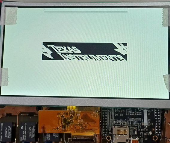
Now, I have a new requirement: adding a splash image to U-Boot.
I am following the ‘09_03_05_02’ guide from the Linux SDK, where this feature was recently added, but I am still not completely clear on the exact steps.
My idea is to use the SDK to compile a new U-Boot on my host PC, first configuring it according to section ‘3.1.2.5. U-Boot Splash Screen.’
After compiling, I would like to mount the prebuilt image I already have working on my host PC and replace the original U-Boot with the newly compiled one.
I’m not sure if this is the correct procedure. If anyone could guide me, I would greatly appreciate it.

  • Hi,

    Following is correct.

    SDK to compile a new U-Boot on my host PC, first configuring it according to section ‘3.1.2.5. U-Boot Splash Screen.’

    Not sure what you meant by "mount the prebuilt image I already have working on my host PC".
    Have the linux filesystem on SD/eMMC and replace with new U-Boot binaries using the command given at Installing boot binaries in SD/eMMC itself.

  • Hi, thank you in advance for your help. I’ve compiled U-Boot and generated the files MLO, u-boot.bin, and u-boot.img, but since my SD card didn’t have a boot partition (it only has the rootfs partition), I copied MLO and u-boot.img to the /boot directory inside rootfs. Am I doing this correctly, or should I create a separate partition for boot? Also, my second question is that later I need to use commands like fatload mmc 0 $loadaddr archivo.bmp.gz in the U-Boot console, and since it uses fatload, I assume I need a FAT partition on the SD card. Lastly, this BMP image comes with the SDK, and I should copy it to my SD card, right?

  • I have the following files inside the partition on the SD (ls /media/ingenieria3/rootfs/boot):
    -config-5.10.168-ti-r72 -System.map-5.10.168-ti-r72 -uEnv.txt
    -dtbs -ti_logo_414x97_32bpp.bmp.gz -vmlinuz-5.10.168-ti-r72
    -MLO -uboot
    -SOC.sh -u-boot.img
    I successfully loaded the image with ext4load mmc 0:1 $loadaddr /boot/ti_logo_414x97_32bpp.bmp.gz,
    but when I run bmp display $loadaddr, I get:
    Unknown command 'bmp' - try 'help'.
    I already added CONFIG_CMD_BMP to am335x_evm_defconfig and recompiled U-Boot. What could be missing?

  • Hi Rafael,

    , ‘Debian 11.x (Bullseye) Minimal Snapshot,’

    We don't officially offer/support Debian on AM335x, although we do for our more recent devices (check out the AM6x offering). So this being said what we can do here on the E2E is limited but let's try.

     I’ve compiled U-Boot and generated the files MLO, u-boot.bin, and u-boot.img, but since my SD card didn’t have a boot partition (it only has the rootfs partition), I copied MLO and u-boot.img to the /boot directory inside rootfs.

    The way the BeagleBone Black works with the community images is that MLO and U-Boot are loaded in a "raw" fashion from eMMC or SD card, and as such will need to be programmed directly to the media, for example using the `dd` command. This thread here has a ton of applicable info on how to do this: https://forum.beagleboard.org/t/updating-to-2022-u-boot/31598/14   But then also looking some more it seems like newer versions of the BeagleBone Black community software/scripting has moved to filesystem-based boot (MLO and U-Boot would be in a FAT-formatted boot partition). So whatever errors you are seeing are probably due to U-Boot not getting programmed or loaded as expected, but for that we'd need to understand your exact boot flow first.

    Can you share your full boot log so perhaps we can see where U-Boot gets loaded from?

    You can also compare the MLO/U-Boot version string / Git commit IDs with what's in your source tree to see whether and "old" U-Boot is still being used, or the one you built yourself.

    This being said you may or may not run into issues using the TI SDK v9.x U-Boot stack together with that Debian community image; as the BeagleBone U-Boot may have some customizations the image relies on (typical items are "overlays", etc. -- but take this with a grain of salt I haven't looked at that for a while).

    Regards, Andreas

  • Hi Andreas,

    Thanks for your response.

    Attached:
    boot log.txt - Complete boot log
    commands.txt - All compilation commands

    My compiled U-Boot version:
    2a13324e (ti-u-boot-2023.04, tag: 09.03.05)

    Welcome to minicom 2.8
    
    OPTIONS: I18n 
    Port /dev/ttyUSB0, 07:38:41
    
    Press CTRL-A Z for help on special keys
    
    
    U-Boot SPL 2022.04-ge0d31da5 (Aug 04 2023 - 18:48:26 +0000)
    Trying to boot from MMC2
    
    
    U-Boot 2022.04-ge0d31da5 (Aug 04 2023 - 18:48:26 +0000)
    
    CPU  : AM335X-GP rev 2.1
    Model: TI AM335x BeagleBone Black
    DRAM:  512 MiB
    Reset Source: Power-on reset has occurred.
    RTC 32KCLK Source: External.
    Core:  150 devices, 14 uclasses, devicetree: separate
    WDT:   Started wdt@44e35000 with servicing (60s timeout)
    MMC:   OMAP SD/MMC: 0, OMAP SD/MMC: 1
    Loading Environment from EXT4... ** File not found /boot/uboot.env **           
                                                                                    
    ** Unable to read "/boot/uboot.env" from mmc0:1 **                              
    Board: BeagleBone Black                                                         
    <ethaddr> not set. Validating first E-fuse MAC                                  
    BeagleBone Black:                                                               
    BeagleBone Cape EEPROM: no EEPROM at address: 0x54                              
    BeagleBone Cape EEPROM: no EEPROM at address: 0x55                              
    BeagleBone Cape EEPROM: no EEPROM at address: 0x56                              
    BeagleBone Cape EEPROM: found EEPROM at address: 0x57                           
    BeagleBone Cape EEPROM: EEPROM contents not valid (or blank) on address: 0x57   
    Net:   eth2: ethernet@4a100000, eth3: usb_ether                                 
    Press SPACE to abort autoboot in 0 seconds                                      
    => version                                                                      
    U-Boot 2022.04-ge0d31da5 (Aug 04 2023 - 18:48:26 +0000)                         
                                                                                    
    gcc (Debian 10.2.1-6) 10.2.1 20210110                                           
    GNU ld (GNU Binutils for Debian) 2.35.2                                         
    => ext4load mmc 0 $loadaddr /boot/ti_logo_414x97_32bpp.bmp.gz                   
    12285 bytes read in 5 ms (2.3 MiB/s)                                            
    => bmp display $loadaddr                                                        
    Unknown command 'bmp' - try 'help'                                              
    => 


    cd ~/ti-processor-sdk-linux-am335x-evm-09.03.05.02/board-support/ti-u-boot-2023.04+gitAUTOINC+2a13324ec6
    nano configs/am335x_evm_defconfig
    
    CONFIG_SPLASH_SCREEN=y
    CONFIG_SPLASH_SOURCE=y
    CONFIG_SPLASH_SCREEN_ALIGN=y
    CONFIG_HIDE_LOGO_VERSION=y
    CONFIG_AM335X_LCD=y
    CONFIG_VIDEO_BMP_GZIP=y
    CONFIG_BMP_24BPP=y
    CONFIG_BMP_32BPP=y
    CONFIG_BMP=y
    CONFIG_VIDEO=y
    CONFIG_CMD_BMP=y
    CONFIG_SYSCON=y
    CONFIG_REGMAP=y
    CONFIG_CLK_CCF=y
    CONFIG_CLK_TI_AM3_DPLL=y
    CONFIG_CLK_TI_DIVIDER=y
    CONFIG_CLK_TI_MUX=y
    CONFIG_DM_PWM=y
    CONFIG_BACKLIGHT_PWM=y
    CONFIG_PWM_TI_ECAP=y
    
    
    export PATH=$HOME/ti-processor-sdk-linux-am335x-evm-09.03.05.02/external-toolchain-dir/arm-gnu-toolchain-11.3.rel1-x86_64-arm-none-linux-gnueabihf/bin:$PATH
    
    sudo apt-get update
    sudo apt-get install -y build-essential autoconf automake bison flex libmpc-dev \
        libmpcdec6 libmpc3 libmpcdec-dev libssl-dev bc u-boot-tools swig \
        python3 python3-pip
    pip3 install jsonschema pyelftools PyYAML Mako yamllint
    
    make distclean (en caso de haber compilado antes)
    make CROSS_COMPILE=arm-none-linux-gnueabihf- O=am335x_evm am335x_evm_defconfig
    make CROSS_COMPILE=arm-none-linux-gnueabihf- O=am335x_evm
    ls -lh am335x_evm/{MLO,u-boot.bin,u-boot.img}
    sudo cp ~/ti-processor-sdk-linux-am335x-evm-09.03.05.02/board-support/ti-u-boot-2023.04+gitAUTOINC+2a13324ec6/am335x_evm/{MLO,u-boot.img} /media/ingenieria3/rootfs/boot/
    ls -lh /media/ingenieria3/rootfs/boot/{MLO,u-boot.img}
    sudo cp /home/ingenieria3/ti-processor-sdk-linux-am335x-evm-09.03.05.02/board-support/ti-u-boot-2023.04+gitAUTOINC+2a13324ec6/tools/logos/ti_logo_414x97_32bpp.bmp.gz /media/ingenieria3/rootfs/boot/
    ls /media/ingenieria3/rootfs/boot
    
    ls mmc 0
    ext4load mmc 0 $loadaddr /boot/ti_logo_414x97_32bpp.bmp.gz
    bmp display $loadaddr


  • Hi Rafael,

    thanks for the files. Before diving into this deeper I need to ask a question. How do you expect the splash screen feature to work? Do you have an LCD display attached like on the AM335x EVM board? Because that is what is expected, and the only way that is supported by our SDK U-Boot. If you expect a splash screen over HDMI interface, this will NOT work and is NOT supported (there's infrastructure missing such as drivers for the HDMI transmitter and code to configure it, etc.).

    Regards, Andreas

  • Hi Andreas,

    Thanks for the clarification. Yes, I’m using an LCD display, not HDMI.

    Best regards,
    Rafael

  • > U-Boot SPL 2022.04-ge0d31da5 (Aug 04 2023 - 18:48:26 +0000)
    > Trying to boot from MMC2

    Two things here.

    1. This is not the U-Boot you built, you can tell the version is different, and you suspected this already as your `bmp` commands don't work

    2. Booting from "MMC2" means U-Boot is using the second MMC interface/peripheral on the AM335x SoC, which is actually called mmc1 or MMC1 (I know it's confusing). Anyways if you check the BeagleBone Black schematic it shows there's an eMMC module attached, and this is where you are booting from right now. So no wonder your SD-card related changes have no impact.

    In order to need to use U-Boot from the SD card, you need to...

    1. Force SD card boot by holding down a button on the BeagleBone Black during powerup (should be a switch labeled "S2"). The BBB documentation has more info on this.

      ...or...

    2. Erase U-Boot from the eMMC, this way it will automatically fall back to booting from SD card, always

    Then you need to of course have U-Boot installed on the SD card correctly, best is in a dedicated FAT-formatted boot partition.

    Regards, Andreas

  • Thanks for the detailed explanation.

    We've already tried both options to boot U-Boot from the SD card: holding down the S2 button during power-up and also erasing U-Boot from the eMMC. After doing that, the message now shows:

    > Trying to boot from MMC1

    However, we’re still seeing the same version:

    > U-Boot SPL 2022.04-ge0d31da5 (Aug 04 2023 - 18:48:26 +0000)

    So it seems the U-Boot we built is still not being loaded from the SD card.

    Regarding your note about having U-Boot installed on a dedicated FAT-formatted boot partition — we’re not entirely sure how to approach that. We're currently considering three options:

    1. Finding a community-built image for the BeagleBone that meets the board’s requirements and includes SDK support,

    2. Trying to modify the current image to add a proper FAT boot partition,

    3. Or building everything from scratch using the SDK, although this would likely take more time and require deeper knowledge and full command of the process.

    Attached:
    log2.txt with the boot log.

    U-Boot SPL 2022.04-ge0d31da5 (Aug 04 2023 - 18:48:26 +0000)                    
    Trying to boot from MMC1                                                       
                                                                                   
                                                                                   
    U-Boot 2022.04-ge0d31da5 (Aug 04 2023 - 18:48:26 +0000)                        
                                                                                   
    CPU  : AM335X-GP rev 2.1                                                       
    Model: TI AM335x BeagleBone Black                                              
    DRAM:  512 MiB                                                                 
    Reset Source: Power-on reset has occurred.                                     
    RTC 32KCLK Source: External.                                                   
    Core:  150 devices, 14 uclasses, devicetree: separate                          
    WDT:   Started wdt@44e35000 with servicing (60s timeout)                       
    MMC:   OMAP SD/MMC: 0, OMAP SD/MMC: 1                                          
    Loading Environment from EXT4... ** File not found /boot/uboot.env **          
                                                                                   
    ** Unable to read "/boot/uboot.env" from mmc0:1 **                             
    Board: BeagleBone Black                                                        
    <ethaddr> not set. Validating first E-fuse MAC                                 
    BeagleBone Black:                                                              
    BeagleBone Cape EEPROM: no EEPROM at address: 0x54                             
    BeagleBone Cape EEPROM: no EEPROM at address: 0x55                             
    BeagleBone Cape EEPROM: no EEPROM at address: 0x56                             
    BeagleBone Cape EEPROM: no EEPROM at address: 0x57                             
    Net:   eth2: ethernet@4a100000, eth3: usb_ether                                
    Press SPACE to abort autoboot in 0 seconds                                     
    =>    


    Rafael

  • > Trying to boot from MMC1

    However, we’re still seeing the same version:

    > U-Boot SPL 2022.04-ge0d31da5 (Aug 04 2023 - 18:48:26 +0000)

    So it seems the U-Boot we built is still not being loaded from the SD card.

    Can you program the TI AM335x SDK image onto an SD card, and directly boot from that image, to see if you finally get a different U-Boot to load?

    [Image Download URL]
    https://dr-download.ti.com/software-development/software-development-kit-sdk/MD-1BUptXj3op/09.03.05.02/tisdk-default-image-am335x-evm-09.03.05.02.wic.xz

    [How to Boot]
    https://software-dl.ti.com/processor-sdk-linux/esd/AM335X/09_03_05_02/exports/docs/linux/How_to_Guides/Target/How_to_Boot_Beagle_Bone_Black_with_Processor_SDK_Linux.html

    If that works you can then just replace the rootfs partition contents with your Debian distro.

    Regards. Andreas

  • First, I verified that the default SDK image contains two partitions, boot1 and rootfs, as required. Booting with that image gave the following result.

    Attached boot image default: boot image default.txt

    U-Boot SPL 2023.04-ti-g2a13324ec63c (Dec 04 2024 - 17:27:55 +0000)              
    Trying to boot from MMC1                                                        
                                                                                    
                                                                                    
    U-Boot 2023.04-ti-g2a13324ec63c (Dec 04 2024 - 17:27:55 +0000)                  
                                                                                    
    CPU  : AM335X-GP rev 2.1                                                        
    Model: TI AM335x BeagleBone Black                                               
    DRAM:  512 MiB                                                                  
    Core:  160 devices, 18 uclasses, devicetree: separate                           
    WDT:   Started wdt@44e35000 with servicing every 1000ms (60s timeout)           
    NAND:  0 MiB                                                                    
    MMC:   OMAP SD/MMC: 0, OMAP SD/MMC: 1                                           
    Loading Environment from FAT... Unable to read "uboot.env" from mmc0:1...       
    <ethaddr> not set. Validating first E-fuse MAC                                  
    Net:   eth2: ethernet@4a100000, eth3: usb_ether                                 
    Hit any key to stop autoboot:  0                                                
    =>
    

    Then, I replaced the MLO, u-boot.img, and ti_logo files, rebooted the system, and got this result

    Attached boot image default + compiled u-boot: boot image default + u-boot splash.txt

    U-Boot SPL 2023.04-dirty (May 12 2025 - 07:48:02 -0300)                         
    Trying to boot from MMC1                                                        
                                                                                    
                                                                                    
    U-Boot 2023.04-dirty (May 12 2025 - 07:48:02 -0300)                             
                                                                                    
    CPU  : AM335X-GP rev 2.1                                                        
    Model: TI AM335x BeagleBone Black                                               
    DRAM:  512 MiB                                                                  
    Video device 'lcdc@0' cannot allocate frame buffer memory -ensure the device isn
    Error binding driver 'tilcdc': -28                                              
    Some drivers failed to bind                                                     
    Error binding driver 'ti_sysc': -28                                             
    Some drivers failed to bind                                                     
    Error binding driver 'simple_bus': -28                                          
    Some drivers failed to bind                                                     
    Error binding driver 'simple_bus': -28                                          
    Some drivers failed to bind                                                     
    Error binding driver 'simple_bus': -28                                          
    Some drivers failed to bind                                                     
    initcall sequence 9ffdae84 failed at call 80818495 (err=-28)                    
    ### ERROR ### Please RESET the board ###
    

    As you can see, now the U-Boot I compiled is loaded, but a memory error appears.

    I just remembered I hadn’t copied my custom uEnv.txt (configured in my Debian environment) to the SDK image. After copying it, the memory error persists. Here’s my uEnv.txt configuration in case it helps: uEnv.txt

    #Docs: http://elinux.org/Beagleboard:U-boot_partitioning_layout_2.0
    
    uname_r=5.10.168-ti-r72
    #uuid=
    #dtb=
    
    ###U-Boot Overlays###
    ###Documentation: http://elinux.org/Beagleboard:BeagleBoneBlack_Debian#U-Boot_Overlays
    ###Master Enable
    enable_uboot_overlays=1
    ###
    ###Overide capes with eeprom
    uboot_overlay_addr0=/lib/firmware/BB-BONE-4D7N-01-00A1.dtbo
    uboot_overlay_addr1=/lib/firmware/BB-I2C2-00A0.dtbo
    uboot_overlay_addr2=/lib/firmware/BB-I2C2-RTC-DS3231.dtbo
    #uboot_overlay_addr3=<file3>.dtbo
    ###
    ###Additional custom capes
    #uboot_overlay_addr4=<file4>.dtbo
    #uboot_overlay_addr5=<file5>.dtbo
    #uboot_overlay_addr6=<file6>.dtbo
    #uboot_overlay_addr7=<file7>.dtbo
    ###
    ###Custom Cape
    #dtb_overlay=<file8>.dtbo
    ###
    ###Disable auto loading of virtual capes (emmc/video/wireless/adc)
    #disable_uboot_overlay_emmc=1
    disable_uboot_overlay_video=1
    disable_uboot_overlay_audio=1
    disable_uboot_overlay_wireless=1
    #disable_uboot_overlay_adc=1
    ###
    ###Cape Universal Enable
    enable_uboot_cape_universal=1
    ###
    ###Debug: disable uboot autoload of Cape
    #disable_uboot_overlay_addr0=1
    #disable_uboot_overlay_addr1=1
    #disable_uboot_overlay_addr2=1
    #disable_uboot_overlay_addr3=1
    ###
    ###U-Boot fdt tweaks... (60000 = 384KB)
    #uboot_fdt_buffer=0x60000
    ###U-Boot Overlays###
    
    console=ttyS0,115200n8
    cmdline=coherent_pool=1M net.ifnames=0 lpj=1990656 rng_core.default_quality=100 quiet
    
    #In the event of edid real failures, uncomment this next line:
    #cmdline=coherent_pool=1M net.ifnames=0 lpj=1990656 rng_core.default_quality=100 quiet video=HDMI-A-1:1024x768@60e
    
    #Use an overlayfs on top of a read-only root filesystem:
    #cmdline=coherent_pool=1M net.ifnames=0 lpj=1990656 rng_core.default_quality=100 quiet overlayroot=tmpfs
    
    ##enable Generic eMMC Flasher:
    #cmdline=init=/usr/sbin/init-beagle-flasher


    Finally, since I noticed that the uEnv.txt includes overlays that depend on the filesystem, I used rsync to copy the Debian rootfs to the SDK image. However, the memory error still persists.

  • I'm currently traveling so I can't look at this in detail, but since you mention "memory error", can you compare the DDR size definitions in the device tree file of the AM335x EVM board (for which the LCD demo is intended for) and the board you are using, to see if there are differences. I think the BBB has 512MB, but the AM335x EVM has 1GB. So depending how memory is allocated this could be your issue; and you'd need to check and update these definitions and rearrange the memory map in a way that fits for BBB. Also I think there are BeagleBone variants with 1GB DDR that you could potentially use.

    Regards, Andreas

  • Thanks for the guidance. What you're saying is that the u-boot with splash that I compiled is prepared for the AM335x EVM and not for the BeagleBone Black (BBB), which could be causing the memory issue?

    I noticed that in my uEnv.txt file, the 'dtb' line is commented out, so I'm not sure which 'dtb' file the boot process is referring to.

    In the boot partition (/media/path/boot1) of the u-boot I built, I found the 'am335x-boneblack.dtb' file, and inside it, it contains this code:

    memory@80000000 {
    device_type = "memory"; reg = <0x80000000 0x20000000>;
    };

    While the am335x-evm.dtb file has this other code:

    memory@80000000 {
    device_type = "memory"; reg = <0x80000000 0x10000000>;
    };

    I'm not sure if this is what you were referring to.

    On another note, I came across a discussion in the forum "https://e2e.ti.com/support/processors-group/processors/f/processors-forum/1459592/processor-sdk-am335x-uboot-splash-screen" where someone had a similar memory issue. Although they mention using device trees and patches, I don't fully understand how they resolved it. Could you help clarify it for me?

  • I'm currently traveling international for business. Please allow a few days for a response.

  • Thank you for letting me know, Andreas. I’ll wait for your reply once you’re back and available. Wishing you a smooth and safe trip.

  • Hi Rafael,

    memory@80000000 {
    device_type = "memory"; reg = <0x80000000 0x20000000>;
    };

    While the am335x-evm.dtb file has this other code:

    memory@80000000 {
    device_type = "memory"; reg = <0x80000000 0x10000000>;
    };

    I'm not sure if this is what you were referring to.

    Yes that is what I was referring to. You can see the BBB has 512MB, whereas the AM335x EVM has 1GB.

    While this is a difference it may actually not matter. Because I just searched in the E2E and found this post here, that shows the same error message that you are experiencing:

    https://e2e.ti.com/support/processors-group/processors/f/processors-forum/1459592/processor-sdk-am335x-uboot-splash-screen/5600267

    In this E2E thread, a custom board with only 256MB of DDR is used which is less than what you have, and the LCD splash screen was made work. Looking at the DTS file posted there I don't see any references regarding that the DDR size or display buffer placement or anything like that would matter for this concern.

    The solution proposed there was adding "bootph-all" to key DTS nodes for the U-Boot stage, which can simply be accomplished by including the "am335x-evm-u-boot.dtsi" file, in your case into "am335x-boneblack.dts". Can you give this a try and see if this gets you past the error.

    Regards, Andreas

  • Hi Andreas,

    Thank you for your previous guidance. Following your suggestions:

    1. DTB Fix: I included am335x-evm-u-boot.dtsi in am335x-boneblack.dts, recompiled the DTB, and loaded the changes. This resolved the memory error, and the bmp command is now available in U-Boot.

    2. BMP Loading: I successfully loaded the image into memory:

      fatload mmc 0 $loadaddr ti_logo_414x97_32bpp.bmp.gz  

      (12,285 bytes read, no errors).

    3. Issue: When running:

      bmp display $loadaddr m m  

      No output appearsno error messages, no visual output on the display, and no changes to the console.

    In the E2E thread, the user resolved this by adding LCD pinmux configuration:

    lcd_pin_mux and configure_module_pin_mux(lcd_pin_mux)


    What do you recommend I try next?

  • Hi Rafael,

    What do you recommend I try next?

    Another post had an issue with the backlight not getting turned on, making the LCD appear black. You may want to double check this (measuring at the LCD will be best).

    Along the same lines, use a logic analyzer and probe the LCD lines to see if there is any meaningful activity. This will be helpful to narrow down where the issue might be (pinmux, connections, electrical, timing, etc.)

    Regards, Andreas

  • Hi Andreas,

    Thank you for your continued support.

    Following your suggestions, we performed measurements after running the bmp display $loadaddr m m command. We confirmed that the LCD backlight is correctly powered. However, when we probed the LCD data and control lines, we did not detect any activity—no transitions or signal changes were observed.

    Just to provide full context, in our current Debian image setup, the only configuration related to the LCD is the following device tree overlay:

    uboot_overlay_addr0=/lib/firmware/BB-BONE-4D7N-01-00A1.dtbo

    This is the only modification we’ve made to enable the LCD. We haven't applied any additional pinmux settings or custom DT configurations beyond this overlay.

    Please let us know what you recommend as the next step.

    Best regards,
    Rafael Flores

  • Hi Rafael,

    first, you should check your Kernel log for any signs of display driver probing/activity. You can search for 'drm' and 'lcd' and see if there's anything. I don't have this setup so I can't tell you exactly what to expect so you need to figure this out yourself. You could also instrument the LCD peripheral driver at drivers/gpu/drm/tilcdc/tilcdc_drv.c with some printk() type instructions for example in the probe and init functions to see if those are called. This would mean your device tree changes got applied correctly.

    Also once your system is booted up you can also examine the effective device tree by accessing it through the sysfs interface at /sys/firmware/devicetree/base/. If you navigate around there you should be able to determine if your display-related settings got applied correctly or not.

    Regards, Andreas

  • Hi Andreas,

    Thanks for your detailed response.

    I followed your suggestions and ran dmesg | grep drm and dmesg | grep lcd.
    I also explored /sys/firmware/devicetree/base/. Below, I’ve attached the contents of the log.txt file with the results I obtained:

    -----------------------------------------------------------------------------------------------
    debian@BeagleBone:~$ dmesg | grep drm                                        
    [   11.522778] systemd[1]: Starting Load Kernel Module drm...                   
    [   31.059946] [drm] Initialized tilcdc 1.0.0 20121205 for 4830e000.lcdc on min0
    [   31.155585] tilcdc 4830e000.lcdc: [drm] Cannot find any crtc or sizes   
    [   31.222327] tilcdc 4830e000.lcdc: [drm] Cannot find any crtc or sizes
    [   32.416455] [drm] Initialized pvr 1.17.4948957 20110701 for 56000000.gpu on 1
    debian@BeagleBone:~$ dmesg | grep lcd
    [    1.958226] platform 4830e000.lcdc: Fixed dependency cycle(s) with /ocp/inte0
    [    2.495647] platform 4830e000.lcdc: Fixed dependency cycle(s) with /ocp/inte0
    [    2.508910] i2c 0-0070: Fixed dependency cycle(s) with /ocp/interconnect@4800
    [   30.976171] tilcdc 4830e000.lcdc: bound 0-0070 (ops tda998x_audio_codec_init)
    [   31.059946] [drm] Initialized tilcdc 1.0.0 20121205 for 4830e000.lcdc on min0
    [   31.155585] tilcdc 4830e000.lcdc: [drm] Cannot find any crtc or sizes        
    [   31.222327] tilcdc 4830e000.lcdc: [drm] Cannot find any crtc or sizes
    -----------------------------------------------------------------------------------------------
    debian@BeagleBone:/sys/firmware/devicetree/base$ ls 
    '#address-cells'   clk_mcasp0_fixed   memory@80000000   soc                     
    '#size-cells'      compatible         model             sound                   
     __symbols__       cpus               name              target-module@4b000000  
     aliases           fixedregulator0    ocp                                       
     chosen            interrupt-parent   opp-table                                 
     clk_mcasp0        leds               serial-number 
     
     debian@BeagleBone:/sys/firmware/devicetree/base$ find . | grep -i lcd           
    ./__symbols__/lcdc_0                                                            
    ./__symbols__/lcd_gclk                                                          
    ./__symbols__/lcdc_clkctrl                                                      
    ./__symbols__/lcdc                                                              
    ./ocp/interconnect@48000000/segment@300000/target-module@e000/lcdc@0            
    ./ocp/interconnect@48000000/segment@300000/target-module@e000/lcdc@0/compatible 
    ./ocp/interconnect@48000000/segment@300000/target-module@e000/lcdc@0/port       
    ./ocp/interconnect@48000000/segment@300000/target-module@e000/lcdc@0/port/endpo0
    ./ocp/interconnect@48000000/segment@300000/target-module@e000/lcdc@0/port/endpot
    ./ocp/interconnect@48000000/segment@300000/target-module@e000/lcdc@0/port/endpoe
    ./ocp/interconnect@48000000/segment@300000/target-module@e000/lcdc@0/port/endpoe
    ./ocp/interconnect@48000000/segment@300000/target-module@e000/lcdc@0/port/name  
    ./ocp/interconnect@48000000/segment@300000/target-module@e000/lcdc@0/status     
    ./ocp/interconnect@48000000/segment@300000/target-module@e000/lcdc@0/interrupts 
    ./ocp/interconnect@48000000/segment@300000/target-module@e000/lcdc@0/phandle    
    ./ocp/interconnect@48000000/segment@300000/target-module@e000/lcdc@0/blue-and-rg
    ./ocp/interconnect@48000000/segment@300000/target-module@e000/lcdc@0/reg        
    ./ocp/interconnect@48000000/segment@300000/target-module@e000/lcdc@0/name       
    ./ocp/interconnect@44c00000/segment@200000/target-module@0/prcm@0/clocks/clock-4
    ./ocp/interconnect@44c00000/segment@200000/target-module@0/prcm@0/clocks/clock-e
    ./ocp/interconnect@44c00000/segment@200000/target-module@0/prcm@0/clocks/clock-s
    ./ocp/interconnect@44c00000/segment@200000/target-module@0/prcm@0/clocks/clock-s
    ./ocp/interconnect@44c00000/segment@200000/target-module@0/prcm@0/clocks/clock-e
    ./ocp/interconnect@44c00000/segment@200000/target-module@0/prcm@0/clocks/clock-g
    ./ocp/interconnect@44c00000/segment@200000/target-module@0/prcm@0/clocks/clock-s
    ./ocp/interconnect@44c00000/segment@200000/target-module@0/prcm@0/clocks/clock-t
    ./ocp/interconnect@44c00000/segment@200000/target-module@0/prcm@0/clocks/clock-e
    -----------------------------------------------------------------------------------------------


    As for printk(), I haven't done that yet because I haven’t gone through the kernel compilation process — I still need to study it. So far, I’ve only compiled U-Boot with the configurations you mentioned. Also, just a reminder that the root filesystem is Debian, which I copied using rsync.

    Finally, I’m attaching the boot log from the Debian image currently running on my hardware, so you can compare:

    ----------------------------------------------------------------------------------------------
    debian@BeagleBone:~$ dmesg | grep drm                                           
    [    7.967017] [drm] Initialized tilcdc 1.0.0 20121205 for 4830e000.lcdc on min0
    [    8.007182] tilcdc 4830e000.lcdc: [drm] fb0: tilcdcdrmfb frame buffer device 
    [   11.559438] systemd[1]: Starting Load Kernel Module drm...                   
    [   11.952162] systemd[1]: modprobe@drm.service: Succeeded.                     
    [   11.981077] systemd[1]: Finished Load Kernel Module drm.                     
    debian@BeagleBone:~$ dmesg | grep lcd                                           
    [    0.156427] platform 4830e000.fb: Cannot lookup hwmod 'lcdc'                 
    [    7.936278] tilcdc 4830e000.fb: failed to get functional clock               
    [    7.942277] WARNING: CPU: 0 PID: 1 at drivers/clk/clk.c:4261 tilcdc_fini+0x6c
    [    7.942426] [<c0ee84a8>] (warn_slowpath_fmt) from [<c09bb464>] (tilcdc_fini+)
    [    7.942442] [<c09bb464>] (tilcdc_fini) from [<c09bb800>] (tilcdc_init.constp)
    [    7.942455] [<c09bb800>] (tilcdc_init.constprop.0) from [<c09bbb6c>] (tilcdc)
    [    7.942471] [<c09bbb6c>] (tilcdc_pdev_probe) from [<c09e7310>] (platform_drv)
    [    7.943850] OF: graph: no port node found in /ocp/interconnect@48000000/segm0
    [    7.954630] OF: graph: no port node found in /ocp/interconnect@48000000/segm0
    [    7.967017] [drm] Initialized tilcdc 1.0.0 20121205 for 4830e000.lcdc on min0
    [    8.007182] tilcdc 4830e000.lcdc: [drm] fb0: tilcdcdrmfb frame buffer device 
    debian@BeagleBone:~$ 
    ----------------------------------------------------------------------------------------------
    debian@BeagleBone:/sys/firmware/devicetree/base$ find . | grep -i lcd           
    ./__symbols__/lcd_gclk                                                          
    ./__symbols__/bb_lcd_pwm_backlight_pins                                         
    ./__symbols__/lcdc_clkctrl                                                      
    ./__symbols__/bb_lcd_lcd_pins                                                   
    ./__symbols__/lcdc                                                              
    ./ocp/interconnect@48000000/segment@300000/target-module@e000/lcdc@0            
    ./ocp/interconnect@48000000/segment@300000/target-module@e000/lcdc@0/compatible 
    ./ocp/interconnect@48000000/segment@300000/target-module@e000/lcdc@0/status     
    ./ocp/interconnect@48000000/segment@300000/target-module@e000/lcdc@0/interrupts 
    ./ocp/interconnect@48000000/segment@300000/target-module@e000/lcdc@0/phandle    
    ./ocp/interconnect@48000000/segment@300000/target-module@e000/lcdc@0/reg        
    ./ocp/interconnect@48000000/segment@300000/target-module@e000/lcdc@0/name       
    ./ocp/interconnect@44c00000/segment@200000/target-module@0/prcm@0/clocks/lcd_gc4
    ./ocp/interconnect@44c00000/segment@200000/target-module@0/prcm@0/clocks/lcd_gce
    ./ocp/interconnect@44c00000/segment@200000/target-module@0/prcm@0/clocks/lcd_gcs
    ./ocp/interconnect@44c00000/segment@200000/target-module@0/prcm@0/clocks/lcd_gcs
    ./ocp/interconnect@44c00000/segment@200000/target-module@0/prcm@0/clocks/lcd_gce
    ./ocp/interconnect@44c00000/segment@200000/target-module@0/prcm@0/clocks/lcd_gcg
    ./ocp/interconnect@44c00000/segment@200000/target-module@0/prcm@0/clocks/lcd_gct
    ./ocp/interconnect@44c00000/segment@200000/target-module@0/prcm@0/clocks/lcd_gce
    ./ocp/interconnect@44c00000/segment@200000/target-module@0/prcm@0/per-cm@0/lcdc8
    ./ocp/interconnect@44c00000/segment@200000/target-module@0/prcm@0/per-cm@0/lcdce
    ./ocp/interconnect@44c00000/segment@200000/target-module@0/prcm@0/per-cm@0/lcdcs
    ./ocp/interconnect@44c00000/segment@200000/target-module@0/prcm@0/per-cm@0/lcdce
    ./ocp/interconnect@44c00000/segment@200000/target-module@0/prcm@0/per-cm@0/lcdcg
    ./ocp/interconnect@44c00000/segment@200000/target-module@0/prcm@0/per-cm@0/lcdce
    ./ocp/interconnect@44c00000/segment@200000/target-module@10000/scm@0/pinmux@800s
    ./ocp/interconnect@44c00000/segment@200000/target-module@10000/scm@0/pinmux@800s
    ./ocp/interconnect@44c00000/segment@200000/target-module@10000/scm@0/pinmux@800e
    ./ocp/interconnect@44c00000/segment@200000/target-module@10000/scm@0/pinmux@800e
    ./ocp/interconnect@44c00000/segment@200000/target-module@10000/scm@0/pinmux@800s
    ./ocp/interconnect@44c00000/segment@200000/target-module@10000/scm@0/pinmux@800s
    ./ocp/interconnect@44c00000/segment@200000/target-module@10000/scm@0/pinmux@800e
    ./ocp/interconnect@44c00000/segment@200000/target-module@10000/scm@0/pinmux@800e
    debian@BeagleBone:/sys/firmware/devicetree/base$ 
    ---------------------------------------------------------------------------------------------


    Best regards,
    Rafael

  • Hi Andreas,

    Just following up briefly on this — I understand you're busy, so no pressure.

    Based on our previous exchange, I started thinking the issue might be related to how overlays are handled in the TI SDK. In Debian, I can enable the LCD by simply adding BB-BONE-LCD7-01-00A3.dtbo to uEnv.txt, and it works fine.

    However, in the SDK, even with the same overlay, it doesn’t seem to take effect. So my question is:

    Does the TI SDK actually support loading overlays via uEnv.txt like Debian does, or should the LCD setup be described manually in the .dts and rebuilt?

    It seems likely the problem comes from the overlay not being applied correctly.

    Thanks again,
    Rafael

  • Hi Rafael,

    Does the TI SDK actually support loading overlays via uEnv.txt like Debian does, or should the LCD setup be described manually in the .dts and rebuilt?

    No, this is a BeagleBone community-specific feature and not available in mainline and TI SDKs. You'll need to apply/integrate the DTS changes manually. Or you can still use U-Boot / U-Boot scripting to apply overlays (by adding them to the `name_overlays` U-Boot ENV variable, at least in our current v11 SDKs for other platforms-- not sure about AM335x SDK v9.x).

    Sounds like you'd first want to do the manual integration approach to see if you can get it to work at all in the TI SDK context before worrying about the best way to integrate.

    Regards, Andreas

  • Hi Andreas,

    Thanks again for your continued support.

    As part of debugging the LCD splash screen, I wanted to share the process I’ve followed and some files with you:

    • First, I’m attaching the overlay I used successfully under Debian (BB-BONE-4D7N-01-00A1.dts). This overlay activates the LCD on boot.

      // SPDX-License-Identifier: GPL-2.0-only
      
      /*
      
       * Copyright (C) 2012 Texas Instruments Incorporated - https://www.ti.com/
      
       */


      /dts-v1/;
      
      /plugin/;


      #include <dt-bindings/gpio/gpio.h>
      
      #include <dt-bindings/pinctrl/am33xx.h>
      
      #include <dt-bindings/board/am335x-bbw-bbb-base.h>


      /*
      
       * Helper to show loaded overlays under: /proc/device-tree/chosen/overlays/
      
       */
      
      &{/chosen} {
      
      	overlays {
      
      		BB-BONE-4D7N-01-00A1.bb.org-overlays = __TIMESTAMP__;
      
      	};
      
      };


      / {
      
      	/*
      
      	 * Free up the pins used by the cape from the pinmux helpers.
      
      	 */
      
      	fragment@1 {
      
      		target = <&ocp>;
      
      		__overlay__ {
      
      			P8_45_pinmux { status = "disabled"; };	/* lcd: lcd_data0 */
      
      			P8_46_pinmux { status = "disabled"; };	/* lcd: lcd_data1 */
      
      			P8_43_pinmux { status = "disabled"; };	/* lcd: lcd_data2 */
      
      			P8_44_pinmux { status = "disabled"; };	/* lcd: lcd_data3 */
      
      			P8_41_pinmux { status = "disabled"; };	/* lcd: lcd_data4 */
      
      			P8_42_pinmux { status = "disabled"; };	/* lcd: lcd_data5 */
      
      			P8_39_pinmux { status = "disabled"; };	/* lcd: lcd_data6 */
      
      			P8_40_pinmux { status = "disabled"; };	/* lcd: lcd_data7 */
      
      			P8_37_pinmux { status = "disabled"; };	/* lcd: lcd_data8 */
      
      			P8_38_pinmux { status = "disabled"; };	/* lcd: lcd_data9 */
      
      			P8_36_pinmux { status = "disabled"; };	/* lcd: lcd_data10 */
      
      			P8_34_pinmux { status = "disabled"; };	/* lcd: lcd_data11 */
      
      			P8_35_pinmux { status = "disabled"; };	/* lcd: lcd_data12 */
      
      			P8_33_pinmux { status = "disabled"; };	/* lcd: lcd_data13 */
      
      			P8_31_pinmux { status = "disabled"; };	/* lcd: lcd_data14 */
      
      			P8_32_pinmux { status = "disabled"; };	/* lcd: lcd_data15 */


      			P8_27_pinmux { status = "disabled"; };	/* lcd: lcd_vsync */
      
      			P8_29_pinmux { status = "disabled"; };	/* lcd: lcd_hsync */
      
      			P8_28_pinmux { status = "disabled"; };	/* lcd: lcd_pclk */
      
      			P8_30_pinmux { status = "disabled"; };	/* lcd: lcd_ac_bias_en */


      			P9_27_pinmux { status = "disabled"; };	/* lcd: gpio3_19 DISPEN */


      			P9_14_pinmux { status = "disabled"; };	/* pwm: ehrpwm1a PWM_BL */
      
      		};
      
      	};


      	fragment@2 {
      
      		target = <&am33xx_pinmux>;
      
      		__overlay__ {


      			bb_lcd_pwm_backlight_pins: pinmux_bb_lcd_pwm_backlight_pins {
      
      				pinctrl-single,pins = <
      
      					BONE_P9_14 0x06	/* gpmc_a2.ehrpwm1a, OMAP_MUX_MODE6 | AM33XX_PIN_OUTPUT */
      
      				>;
      
      			};


      			bb_lcd_lcd_pins: pinmux_bb_lcd_lcd_pins {
      
      				pinctrl-single,pins = <
      
      					BONE_P8_45 (PIN_OUTPUT | MUX_MODE0) /* lcd: lcd_data0.lcd_data0 */
      
      					BONE_P8_46 (PIN_OUTPUT | MUX_MODE0) /* lcd: lcd_data1.lcd_data1 */
      
      					BONE_P8_43 (PIN_OUTPUT | MUX_MODE0) /* lcd: lcd_data2.lcd_data2 */
      
      					BONE_P8_44 (PIN_OUTPUT | MUX_MODE0) /* lcd: lcd_data3.lcd_data3 */
      
      					BONE_P8_41 (PIN_OUTPUT | MUX_MODE0) /* lcd: lcd_data4.lcd_data4 */
      
      					BONE_P8_42 (PIN_OUTPUT | MUX_MODE0) /* lcd: lcd_data5.lcd_data5 */
      
      					BONE_P8_39 (PIN_OUTPUT | MUX_MODE0) /* lcd: lcd_data6.lcd_data6 */
      
      					BONE_P8_40 (PIN_OUTPUT | MUX_MODE0) /* lcd: lcd_data7.lcd_data7 */
      
      					BONE_P8_37 (PIN_OUTPUT | MUX_MODE0) /* lcd: lcd_data8.lcd_data8 */
      
      					BONE_P8_38 (PIN_OUTPUT | MUX_MODE0) /* lcd: lcd_data9.lcd_data9 */
      
      					BONE_P8_36 (PIN_OUTPUT | MUX_MODE0) /* lcd: lcd_data10.lcd_data10 */
      
      					BONE_P8_34 (PIN_OUTPUT | MUX_MODE0) /* lcd: lcd_data11.lcd_data11 */
      
      					BONE_P8_35 (PIN_OUTPUT | MUX_MODE0) /* lcd: lcd_data12.lcd_data12 */
      
      					BONE_P8_33 (PIN_OUTPUT | MUX_MODE0) /* lcd: lcd_data13.lcd_data13 */
      
      					BONE_P8_31 (PIN_OUTPUT | MUX_MODE0) /* lcd: lcd_data14.lcd_data14 */
      
      					BONE_P8_32 (PIN_OUTPUT | MUX_MODE0) /* lcd: lcd_data15.lcd_data15 */


      					BONE_P8_27 (PIN_OUTPUT | MUX_MODE0) /* lcd: lcd_vsync.lcd_vsync */
      
      					BONE_P8_29 (PIN_OUTPUT | MUX_MODE0) /* lcd: lcd_hsync.lcd_hsync */
      
      					BONE_P8_28 (PIN_OUTPUT | MUX_MODE0) /* lcd: lcd_pclk.lcd_pclk */
      
      					BONE_P8_30 (PIN_OUTPUT | MUX_MODE0) /* lcd: lcd_ac_bias_en.lcd_ac_bias_en */


      					0x1a4 0x17	/* mcasp0_fsr.gpio3_19, OUTPUT | MODE7  LCD DISEN */
      
      				>;
      
      			};
      
      		};
      
      	};


      	fragment@3 {
      
      		target = <&epwmss1>;
      
      		__overlay__ {
      
      			status = "okay";
      
      		};
      
      	};


      	fragment@4 {
      
      		target = <&ehrpwm1>;
      
      		__overlay__ {
      
      			pinctrl-names = "default";
      
      			pinctrl-0 = <&bb_lcd_pwm_backlight_pins>;
      
      			status = "okay";
      
      		};
      
      	};


      	fragment@6 {
      
      		target = <&lcdc>;
      
      		__overlay__ {
      
      			status = "okay";
      
      		};
      
      	};


      	fragment@7 {
      
      		target-path="/";
      
      		__overlay__ {


      			/* avoid stupid warning */
      
      			#address-cells = <1>;
      
      			#size-cells = <1>;


      			backlight {
      
      				status = "okay";
      
      				compatible = "pwm-backlight";
      
      				pwms = <&ehrpwm1 0 500000 0>;
      
      				brightness-levels = <
      
      					0  1  2  3  4  5  6  7  8  9
      
      					10 11 12 13 14 15 16 17 18 19
      
      					20 21 22 23 24 25 26 27 28 29
      
      					30 31 32 33 34 35 36 37 38 39
      
      					40 41 42 43 44 45 46 47 48 49
      
      					50 51 52 53 54 55 56 57 58 59
      
      					60 61 62 63 64 65 66 67 68 69
      
      					70 71 72 73 74 75 76 77 78 79
      
      					80 81 82 83 84 85 86 87 88 89
      
      					90 91 92 93 94 95 96 97 98 99
      
      					100
      
      				>;
      
      				default-brightness-level = <100>;
      
      			};


      			panel {
      
      				status = "okay";
      
      				compatible = "ti,tilcdc,panel";
      
      				pinctrl-names = "default";
      
      				pinctrl-0 = <&bb_lcd_lcd_pins>;
      
      				panel-info {
      
      					ac-bias           = <255>;
      
      					ac-bias-intrpt    = <0>;
      
      					dma-burst-sz      = <16>;
      
      					bpp               = <16>;
      
      					fdd               = <0x80>;
      
      					sync-edge         = <0>;
      
      					sync-ctrl         = <1>;
      
      					raster-order      = <0>;
      
      					fifo-th           = <0>;
      
      				};


      				display-timings {
      
      					native-mode = <&timing0>;
      
      					/* Settings for ThreeFive S9700RTWV35TR / LCD7 cape: */
      
      					timing0: 800x480 {
      
      						clock-frequency = <30000000>;
      
      						hactive = <800>;
      
      						vactive = <480>;
      
      						hfront-porch = <40>;
      
      						hback-porch = <40>;
      
      						hsync-len = <48>;
      
      						vback-porch = <30>;
      
      						vfront-porch = <13>;
      
      						vsync-len = <3>;
      
      						hsync-active = <0>;
      
      						vsync-active = <0>;
      
      						de-active = <1>;
      
      						pixelclk-active = <0>;
      
      					};
      
      				};
      
      			};


      			fb {
      
      				compatible = "ti,am33xx-tilcdc";
      
      				reg = <0x4830e000 0x1000>;
      
      				interrupt-parent = <&intc>;
      
      				interrupts = <36>;
      
      				ti,hwmods = "lcdc";
      
      			};
      
      		};
      
      	};
      
      };
      
    • Then, I’m also attaching the original am335x-boneblack.dts from the TI SDK (09.03.05.02), unmodified.
      // SPDX-License-Identifier: GPL-2.0-only
      /*
       * Copyright (C) 2012 Texas Instruments Incorporated - https://www.ti.com/
       */
      /dts-v1/;
      
      #include "am33xx.dtsi"
      #include "am335x-bone-common.dtsi"
      #include "am335x-boneblack-common.dtsi"
      #include "am335x-boneblack-hdmi.dtsi"
      
      / {
      	model = "TI AM335x BeagleBone Black";
      	compatible = "ti,am335x-bone-black", "ti,am335x-bone", "ti,am33xx";
      };
      
      &cpu0_opp_table {
      	/*
      	 * All PG 2.0 silicon may not support 1GHz but some of the early
      	 * BeagleBone Blacks have PG 2.0 silicon which is guaranteed
      	 * to support 1GHz OPP so enable it for PG 2.0 on this board.
      	 */
      	oppnitro-1000000000 {
      		opp-supported-hw = <0x06 0x0100>;
      	};
      };
      
      &gpio0 {
      	gpio-line-names =
      		"[mdio_data]",
      		"[mdio_clk]",
      		"P9_22 [spi0_sclk]",
      		"P9_21 [spi0_d0]",
      		"P9_18 [spi0_d1]",
      		"P9_17 [spi0_cs0]",
      		"[mmc0_cd]",
      		"P8_42A [ecappwm0]",
      		"P8_35 [lcd d12]",
      		"P8_33 [lcd d13]",
      		"P8_31 [lcd d14]",
      		"P8_32 [lcd d15]",
      		"P9_20 [i2c2_sda]",
      		"P9_19 [i2c2_scl]",
      		"P9_26 [uart1_rxd]",
      		"P9_24 [uart1_txd]",
      		"[rmii1_txd3]",
      		"[rmii1_txd2]",
      		"[usb0_drvvbus]",
      		"[hdmi cec]",
      		"P9_41B",
      		"[rmii1_txd1]",
      		"P8_19 [ehrpwm2a]",
      		"P8_13 [ehrpwm2b]",
      		"NC",
      		"NC",
      		"P8_14",
      		"P8_17",
      		"[rmii1_txd0]",
      		"[rmii1_refclk]",
      		"P9_11 [uart4_rxd]",
      		"P9_13 [uart4_txd]";
      };
      
      &gpio1 {
      	gpio-line-names =
      		"P8_25 [mmc1_dat0]",
      		"[mmc1_dat1]",
      		"P8_5 [mmc1_dat2]",
      		"P8_6 [mmc1_dat3]",
      		"P8_23 [mmc1_dat4]",
      		"P8_22 [mmc1_dat5]",
      		"P8_3 [mmc1_dat6]",
      		"P8_4 [mmc1_dat7]",
      		"NC",
      		"NC",
      		"NC",
      		"NC",
      		"P8_12",
      		"P8_11",
      		"P8_16",
      		"P8_15",
      		"P9_15A",
      		"P9_23",
      		"P9_14 [ehrpwm1a]",
      		"P9_16 [ehrpwm1b]",
      		"[emmc rst]",
      		"[usr0 led]",
      		"[usr1 led]",
      		"[usr2 led]",
      		"[usr3 led]",
      		"[hdmi irq]",
      		"[usb vbus oc]",
      		"[hdmi audio]",
      		"P9_12",
      		"P8_26",
      		"P8_21 [emmc]",
      		"P8_20 [emmc]";
      };
      
      &gpio2 {
      	gpio-line-names =
      		"P9_15B",
      		"P8_18",
      		"P8_7",
      		"P8_8",
      		"P8_10",
      		"P8_9",
      		"P8_45 [hdmi]",
      		"P8_46 [hdmi]",
      		"P8_43 [hdmi]",
      		"P8_44 [hdmi]",
      		"P8_41 [hdmi]",
      		"P8_42 [hdmi]",
      		"P8_39 [hdmi]",
      		"P8_40 [hdmi]",
      		"P8_37 [hdmi]",
      		"P8_38 [hdmi]",
      		"P8_36 [hdmi]",
      		"P8_34 [hdmi]",
      		"[rmii1_rxd3]",
      		"[rmii1_rxd2]",
      		"[rmii1_rxd1]",
      		"[rmii1_rxd0]",
      		"P8_27 [hdmi]",
      		"P8_29 [hdmi]",
      		"P8_28 [hdmi]",
      		"P8_30 [hdmi]",
      		"[mmc0_dat3]",
      		"[mmc0_dat2]",
      		"[mmc0_dat1]",
      		"[mmc0_dat0]",
      		"[mmc0_clk]",
      		"[mmc0_cmd]";
      };
      
      &gpio3 {
      	gpio-line-names =
      		"[mii col]",
      		"[mii crs]",
      		"[mii rx err]",
      		"[mii tx en]",
      		"[mii rx dv]",
      		"[i2c0 sda]",
      		"[i2c0 scl]",
      		"[jtag emu0]",
      		"[jtag emu1]",
      		"[mii tx clk]",
      		"[mii rx clk]",
      		"NC",
      		"NC",
      		"[usb vbus en]",
      		"P9_31 [spi1_sclk]",
      		"P9_29 [spi1_d0]",
      		"P9_30 [spi1_d1]",
      		"P9_28 [spi1_cs0]",
      		"P9_42B [ecappwm0]",
      		"P9_27",
      		"P9_41A",
      		"P9_25",
      		"NC",
      		"NC",
      		"NC",
      		"NC",
      		"NC",
      		"NC",
      		"NC",
      		"NC",
      		"NC",
      		"NC";
      };
      
      &baseboard_eeprom {
      	vcc-supply = <&ldo4_reg>;
      };
      
      
    • Since I understand that overlays are not supported the same way in the SDK, I tried to manually merge the overlay into the SDK’s am335x-boneblack.dts. I’m not very experienced with Device Trees, but I did my best to replicate the panel and pinmux configurations.
      //* SPDX-License-Identifier: GPL-2.0-only */
      /*
       * Copyright (C) 2012 Texas Instruments Incorporated
       */
      
      /dts-v1/;
      
      #include "am33xx.dtsi"
      #include "am335x-bone-common.dtsi"
      #include "am335x-boneblack-common.dtsi"
      #include "am335x-evm-u-boot.dtsi"
      // #include "am335x-boneblack-hdmi.dtsi"
      
      / {
          model = "TI AM335x BeagleBone Black";
          compatible = "ti,am335x-bone-black", "ti,am335x-bone", "ti,am33xx";
      
          /* Backlight PWM controller */
          backlight {
              status = "okay";
              compatible = "pwm-backlight";
              pwms = <&ehrpwm1 0 500000 0>;
              brightness-levels = <
                  0 1 2 3 4 5 6 7 8 9
                  10 11 12 13 14 15 16 17 18 19
                  20 21 22 23 24 25 26 27 28 29
                  30 31 32 33 34 35 36 37 38 39
                  40 41 42 43 44 45 46 47 48 49
                  50 51 52 53 54 55 56 57 58 59
                  60 61 62 63 64 65 66 67 68 69
                  70 71 72 73 74 75 76 77 78 79
                  80 81 82 83 84 85 86 87 88 89
                  90 91 92 93 94 95 96 97 98 99
                  100
              >;
              default-brightness-level = <100>;
          };
      
          /* LCD panel settings */
          panel {
              status = "okay";
              compatible = "ti,tilcdc,panel";
              pinctrl-names = "default";
              pinctrl-0 = <&bb_lcd_lcd_pins>;
              panel-info {
                  ac-bias = <255>;
                  ac-bias-intrpt = <0>;
                  dma-burst-sz = <16>;
                  bpp = <16>;
                  fdd = <0x80>;
                  sync-edge = <0>;
                  sync-ctrl = <1>;
                  raster-order = <0>;
                  fifo-th = <0>;
              };
              display-timings {
                  native-mode = <&timing0>;
                  timing0: 800x480 {
                      clock-frequency = <30000000>;
                      hactive = <800>;
                      vactive = <480>;
                      hfront-porch = <40>;
                      hback-porch = <40>;
                      hsync-len = <48>;
                      vback-porch = <30>;
                      vfront-porch = <13>;
                      vsync-len = <3>;
                      hsync-active = <0>;
                      vsync-active = <0>;
                      de-active = <1>;
                      pixelclk-active = <0>;
                  };
              };
          };
      
      
          /* Disable unused peripherals */
          hdmi {
              status = "disabled";
          };
          hdmi_audio: hdmi_audio@0 {
              status = "disabled";
          };
          sound {
              status = "disabled";
          };
          clk_mcasp0_fixed: clk_mcasp0_fixed {
              status = "disabled";
          };
          clk_mcasp0: clk_mcasp0 {
              status = "disabled";
          };
      };
      
      &cpu0_opp_table {
          oppnitro-1000000000 {
              opp-supported-hw = <0x06 0x0100>;
          };
      };
      
      &gpio0 {
          gpio-line-names =
              "[mdio_data]",
              "[mdio_clk]",
      	"P9_22 [spi0_sclk]",
      	"P9_21 [spi0_d0]",
      	"P9_18 [spi0_d1]",
      	"P9_17 [spi0_cs0]",
      	"[mmc0_cd]",
      	"P8_42A [ecappwm0]",
      	"P8_35 [lcd d12]",
      	"P8_33 [lcd d13]",
      	"P8_31 [lcd d14]",
      	"P8_32 [lcd d15]",
      	"P9_20 [i2c2_sda]",
      	"P9_19 [i2c2_scl]",
      	"P9_26 [uart1_rxd]",
      	"P9_24 [uart1_txd]",
      	"[rmii1_txd3]",
      	"[rmii1_txd2]",
      	"[usb0_drvvbus]",
      	"[hdmi cec]",
      	"P9_41B",
      	"[rmii1_txd1]",
      	"P8_19 [ehrpwm2a]",
      	"P8_13 [ehrpwm2b]",
      	"NC",
      	"NC",
      	"P8_14",
      	"P8_17",
      	"[rmii1_txd0]",
      	"[rmii1_refclk]",
      	"P9_11 [uart4_rxd]",
      	"P9_13 [uart4_txd]";
      };
      
      &gpio1 {
          gpio-line-names =
              "P8_25 [mmc1_dat0]",
      	"[mmc1_dat1]",
      	"P8_5 [mmc1_dat2]",
      	"P8_6 [mmc1_dat3]",
      	"P8_23 [mmc1_dat4]",
      	"P8_22 [mmc1_dat5]",
      	"P8_3 [mmc1_dat6]",
      	"P8_4 [mmc1_dat7]",
      	"NC",
      	"NC",
      	"NC",
      	"NC",
      	"P8_12",
      	"P8_11",
      	"P8_16",
      	"P8_15",
      	"P9_15A",
      	"P9_23",
      	"P9_14 [ehrpwm1a]",
      	"P9_16 [ehrpwm1b]",
      	"[emmc rst]",
      	"[usr0 led]",
      	"[usr1 led]",
      	"[usr2 led]",
      	"[usr3 led]",
      	"[hdmi irq]",
      	"[usb vbus oc]",
      	"[hdmi audio]",
      	"P9_12",
      	"P8_26",
      	"P8_21 [emmc]",
      	"P8_20 [emmc]";
      };
      
      &gpio2 {
      	gpio-line-names =
      		"P9_15B",
      		"P8_18",
      		"P8_7",
      		"P8_8",
      		"P8_10",
      		"P8_9",
      		"P8_45 [hdmi]",
      		"P8_46 [hdmi]",
      		"P8_43 [hdmi]",
      		"P8_44 [hdmi]",
      		"P8_41 [hdmi]",
      		"P8_42 [hdmi]",
      		"P8_39 [hdmi]",
      		"P8_40 [hdmi]",
      		"P8_37 [hdmi]",
      		"P8_38 [hdmi]",
      		"P8_36 [hdmi]",
      		"P8_34 [hdmi]",
      		"[rmii1_rxd3]",
      		"[rmii1_rxd2]",
      		"[rmii1_rxd1]",
      		"[rmii1_rxd0]",
      		"P8_27 [hdmi]",
      		"P8_29 [hdmi]",
      		"P8_28 [hdmi]",
      		"P8_30 [hdmi]",
      		"[mmc0_dat3]",
      		"[mmc0_dat2]",
      		"[mmc0_dat1]",
      		"[mmc0_dat0]",
      		"[mmc0_clk]",
      		"[mmc0_cmd]";
      };
      
      &gpio3 {
      gpio-line-names =
      		"[mii col]",
      		"[mii crs]",
      		"[mii rx err]",
      		"[mii tx en]",
      		"[mii rx dv]",
      		"[i2c0 sda]",
      		"[i2c0 scl]",
      		"[jtag emu0]",
      		"[jtag emu1]",
      		"[mii tx clk]",
      		"[mii rx clk]",
      		"NC",
      		"NC",
      		"[usb vbus en]",
      		"P9_31 [spi1_sclk]",
      		"P9_29 [spi1_d0]",
      		"P9_30 [spi1_d1]",
      		"P9_28 [spi1_cs0]",
      		"P9_42B [ecappwm0]",
      		"P9_27",
      		"P9_41A",
      		"P9_25",
      		"NC",
      		"NC",
      		"NC",
      		"NC",
      		"NC",
      		"NC",
      		"NC",
      		"NC",
      		"NC",
      		"NC";
      };
      
      &baseboard_eeprom {
          vcc-supply = <&ldo4_reg>;
      };
      
      &epwmss1 {
          status = "okay";
      };
      
      &ehrpwm1 {
          pinctrl-names = "default";
          pinctrl-0 = <&bb_lcd_pwm_backlight_pins>;
          status = "okay";
      };
      
      &lcdc {
          status = "okay";
      };
      
      &am33xx_pinmux {
          /* Pines para interfaz LCD */
          bb_lcd_lcd_pins: bb_lcd_lcd_pins {
              pinctrl-single,pins = <
                  0xa0 (PIN_OUTPUT | MUX_MODE0) /* lcd_data0 */
                  0xa4 (PIN_OUTPUT | MUX_MODE0) /* lcd_data1 */
                  0xa8 (PIN_OUTPUT | MUX_MODE0) /* lcd_data2 */
                  0xac (PIN_OUTPUT | MUX_MODE0) /* lcd_data3 */
                  0xb0 (PIN_OUTPUT | MUX_MODE0) /* lcd_data4 */
                  0xb4 (PIN_OUTPUT | MUX_MODE0) /* lcd_data5 */
                  0xb8 (PIN_OUTPUT | MUX_MODE0) /* lcd_data6 */
                  0xbc (PIN_OUTPUT | MUX_MODE0) /* lcd_data7 */
                  0xc0 (PIN_OUTPUT | MUX_MODE0) /* lcd_data8 */
                  0xc4 (PIN_OUTPUT | MUX_MODE0) /* lcd_data9 */
                  0xc8 (PIN_OUTPUT | MUX_MODE0) /* lcd_data10 */
                  0xcc (PIN_OUTPUT | MUX_MODE0) /* lcd_data11 */
                  0xd0 (PIN_OUTPUT | MUX_MODE0) /* lcd_data12 */
                  0xd4 (PIN_OUTPUT | MUX_MODE0) /* lcd_data13 */
                  0xd8 (PIN_OUTPUT | MUX_MODE0) /* lcd_data14 */
                  0xdc (PIN_OUTPUT | MUX_MODE0) /* lcd_data15 */
                  0xe0 (PIN_OUTPUT | MUX_MODE0) /* lcd_vsync   */
                  0xe4 (PIN_OUTPUT | MUX_MODE0) /* lcd_hsync   */
                  0xe8 (PIN_OUTPUT | MUX_MODE0) /* lcd_pclk    */
                  0xec (PIN_OUTPUT | MUX_MODE0) /* lcd_ac_bias_en */
              >;
          };
      
          /* Pin PWM para retroiluminación */
          bb_lcd_pwm_backlight_pins: bb_lcd_pwm_backlight_pins {
              pinctrl-single,pins = <
                  0x48 (PIN_OUTPUT_PULLUP | MUX_MODE6)
              >;
          };
      };
      
    • I compiled the resulting DTS, replaced the DTB on the boot partition, and confirmed it is correctly loaded by U-Boot (I set CONFIG_DEFAULT_DEVICE_TREE="am335x-boneblack" and verified it’s used).
    • Current status:

      When I run the following U-Boot commands:

      => fatload mmc 0 $loadaddr ti_logo_414x97_32bpp.bmp.gz
      => bmp display $loadaddr m m

      I get this error:

      Error: 16 bit/pixel mode, but BMP has 0 bit/pixel

      So far I’ve verified:

      • The image is correctly loaded to RAM (12,285 bytes read).

      • The LCD backlight is on.

      • Using an oscilloscope, I see activity on the LCD data and control lines.

      • I tried converting the BMP to 24bpp, but that didn't help.

      • I suspect I may be missing some configuration in the DTS, maybe something related to color depth or display mode.

      Would you have any suggestions as to what could be missing or misconfigured?

      Thanks again for your guidance!

      Best regards,
      Rafael

  • Hi Andreas,

    Following up on my previous message, I wanted to share a few more tests I’ve conducted regarding the splash screen issue.

    I converted the 32bpp compressed BMP image to an uncompressed 16bpp BMP version. Then, using the command:

    => fatload mmc 0 $loadaddr ti_logo_414x97_16bpp.bmp

    U-Boot no longer shows an error message, but the splash still doesn’t appear on the screen.

    Additionally, I recompiled the Device Tree with the following panel-info settings adjusted for 32bpp:

    panel-info { ac-bias = <255>;
    ac-bias-intrpt = <0>;
    dma-burst-sz = <16>;
    bpp = <32>;
    fdd = <0x80>;
    sync-edge = <0>;
    sync-ctrl = <1>;
    raster-order = <0>;
    fifo-th = <0>; };

    I tried again using the 32bpp compressed BMP (ti_logo_414x97_32bpp.bmp.gz), but although no error was reported by U-Boot, the splash still did not show.

    So I suspect there might still be a missing setting in the panel configuration or framebuffer allocation.

    Any advice or insights would be much appreciated.

    Best regards,
    Rafael

  • Hi Rafael,

    glad to see you were able to advance this some. I've re-assigned this thread to our display sub-system (DSS) expert to comment on possible configuration issues.

    Regards, Andreas

  • Hi Andreas,

    Thank you once again for all your help and guidance throughout this debugging process. Your support has been instrumental in getting me this far.

    I appreciate you reassigning the thread to the DSS expert — I’ll continue working on the issue with their input.

    Thanks again, and best regards,
    Rafael

  • Hi Rafael,
    Looking into this internally, please expect a response within 3 days.

  • Hi Divyansh,
    Thanks for the follow-up. I look forward to your response.
    Best,
    Rafael

  • Hi Rafael,
    Apologies for the delay, but one of our other experts is looking into it and we expect them to respond on this soon.

  • Hi Rafael,
    I am working on this issue.
    Is this display working for you in the Kernel?
    If so, are the panel info and display timings both the same in the Kernel and U-Boot?
    Also, do you get the pixel clock (pclk) after running the "bmp display"?
    I have a similar display; I will try it with the BeagleBone Black and update it.

    Regards,

    Sukrut

  • Hi Rafael,

    Are you using 16-bit(LCD_DATA0 - LCD_DATA15) display?
    I have tested the 16-bit display GEN4-4DCAPE-70CT-CLB on the BBB with PFA patches(rename to .patch).
    Looks like you are missing pin muxing changes in mux.c.

    Please ensure that your .config file contains "CONFIG_CLK_TI_GATE=y".
    If you want to display 16bpp BMP on a 16-bit display, then add "CONFIG_BMP_16BPP=y" in your config.

    I have also tested the 24-bit display NHD-7.0CTP-CAPE-N-ND on BBB (this requires additional pin muxing and display/panel info changes).

    Please let us know if this works for you or if you see any issues.

    commit 041263714813cf0b43cab6a083bf367f55d71745
    Author: Sukrut Bellary <sbellary@baylibre.com>
    Date:   Wed Jul 2 16:00:10 2025 -0700
    
        arm: dts: am335x: add LCD and backlight for bbb
        
        Enable PWM for the LCD backlight.
        Add display and panel details for 16-bit gen4-4DCAPE-70CT-CLB display.
        
        Signed-off-by: Sukrut Bellary <sbellary@baylibre.com>
    
    diff --git a/arch/arm/dts/am335x-boneblack.dts b/arch/arm/dts/am335x-boneblack.dts
    index b956e2f60fe0..7c1ef562d5c8 100644
    --- a/arch/arm/dts/am335x-boneblack.dts
    +++ b/arch/arm/dts/am335x-boneblack.dts
    @@ -7,11 +7,90 @@
     #include "am33xx.dtsi"
     #include "am335x-bone-common.dtsi"
     #include "am335x-boneblack-common.dtsi"
    -#include "am335x-boneblack-hdmi.dtsi"
    +#include "am335x-evm-u-boot.dtsi"
    +//#include "am335x-boneblack-hdmi.dtsi"
     
     / {
     	model = "TI AM335x BeagleBone Black";
     	compatible = "ti,am335x-bone-black", "ti,am335x-bone", "ti,am33xx";
    +
    +	backlight: backlight {
    +		status = "okay";
    +		compatible = "pwm-backlight";
    +		pwms = <&ehrpwm1 0 500000 0>;
    +		brightness-levels = <
    +			0  1  2  3  4  5  6  7  8  9
    +			10 11 12 13 14 15 16 17 18 19
    +			20 21 22 23 24 25 26 27 28 29
    +			30 31 32 33 34 35 36 37 38 39
    +			40 41 42 43 44 45 46 47 48 49
    +			50 51 52 53 54 55 56 57 58 59
    +			60 61 62 63 64 65 66 67 68 69
    +			70 71 72 73 74 75 76 77 78 79
    +			80 81 82 83 84 85 86 87 88 89
    +			90 91 92 93 94 95 96 97 98 99
    +			100
    +		>;
    +		default-brightness-level = <100>;
    +	};
    +
    +	panel {
    +		compatible = "ti,tilcdc,panel";
    +		status = "okay";
    +		pinctrl-names = "default";
    +		pinctrl-0 = <&lcd_pins_s0>;
    +		backlight = <&backlight>;
    +		panel-info {
    +			ac-bias           = <255>;
    +			ac-bias-intrpt    = <0>;
    +			dma-burst-sz      = <16>;
    +			bpp               = <16>;
    +			fdd               = <0x80>;
    +			sync-edge         = <0>;
    +			sync-ctrl         = <1>;
    +			raster-order      = <0>;
    +			fifo-th           = <0>;
    +		};
    +
    +		display-timings {
    +			800x480p62 {
    +				clock-frequency = <45000000>;
    +				hactive = <800>;
    +				vactive = <480>;
    +				hfront-porch = <40>;
    +				hback-porch = <40>;
    +				hsync-len = <48>;
    +				vback-porch = <30>;
    +				vfront-porch = <13>;
    +				vsync-len = <3>;
    +				hsync-active = <0>;
    +				vsync-active = <0>;
    +			};
    +		};
    +
    +		port {
    +			panel_0: endpoint@0 {
    +				remote-endpoint = <&lcdc_0>;
    +			};
    +		};
    +	};
    +
    +	/* Disable unused peripherals */
    +	hdmi {
    +		status = "disabled";
    +	};
    +	hdmi_audio: hdmi_audio@0 {
    +		status = "disabled";
    +	};
    +	sound {
    +		status = "disabled";
    +	};
    +	clk_mcasp0_fixed: clk_mcasp0_fixed {
    +		status = "disabled";
    +	};
    +	clk_mcasp0: clk_mcasp0 {
    +		status = "disabled";
    +	};
     };
     
     &cpu0_opp_table {
    @@ -172,3 +251,70 @@
     &baseboard_eeprom {
     	vcc-supply = <&ldo4_reg>;
     };
    +
    +&am33xx_pinmux {
    +	lcd_pins_s0: lcd_pins_s0 {
    +		pinctrl-single,pins = <
    +			AM33XX_PADCONF(AM335X_PIN_GPMC_CLK, PIN_OUTPUT_PULLUP, MUX_MODE7)
    +
    +			AM33XX_PADCONF(AM335X_PIN_LCD_DATA0, PIN_OUTPUT, MUX_MODE0)
    +			AM33XX_PADCONF(AM335X_PIN_LCD_DATA1, PIN_OUTPUT, MUX_MODE0)
    +			AM33XX_PADCONF(AM335X_PIN_LCD_DATA2, PIN_OUTPUT, MUX_MODE0)
    +			AM33XX_PADCONF(AM335X_PIN_LCD_DATA3, PIN_OUTPUT, MUX_MODE0)
    +			AM33XX_PADCONF(AM335X_PIN_LCD_DATA4, PIN_OUTPUT, MUX_MODE0)
    +			AM33XX_PADCONF(AM335X_PIN_LCD_DATA5, PIN_OUTPUT, MUX_MODE0)
    +			AM33XX_PADCONF(AM335X_PIN_LCD_DATA6, PIN_OUTPUT, MUX_MODE0)
    +			AM33XX_PADCONF(AM335X_PIN_LCD_DATA7, PIN_OUTPUT, MUX_MODE0)
    +			AM33XX_PADCONF(AM335X_PIN_LCD_DATA8, PIN_OUTPUT, MUX_MODE0)
    +			AM33XX_PADCONF(AM335X_PIN_LCD_DATA9, PIN_OUTPUT, MUX_MODE0)
    +			AM33XX_PADCONF(AM335X_PIN_LCD_DATA10, PIN_OUTPUT, MUX_MODE0)
    +			AM33XX_PADCONF(AM335X_PIN_LCD_DATA11, PIN_OUTPUT, MUX_MODE0)
    +			AM33XX_PADCONF(AM335X_PIN_LCD_DATA12, PIN_OUTPUT, MUX_MODE0)
    +			AM33XX_PADCONF(AM335X_PIN_LCD_DATA13, PIN_OUTPUT, MUX_MODE0)
    +			AM33XX_PADCONF(AM335X_PIN_LCD_DATA14, PIN_OUTPUT, MUX_MODE0)
    +			AM33XX_PADCONF(AM335X_PIN_LCD_DATA15, PIN_OUTPUT, MUX_MODE0)
    +
    +			AM33XX_PADCONF(AM335X_PIN_GPMC_AD15, PIN_OUTPUT, MUX_MODE1)
    +			AM33XX_PADCONF(AM335X_PIN_GPMC_AD14, PIN_OUTPUT, MUX_MODE1)
    +			AM33XX_PADCONF(AM335X_PIN_GPMC_AD13, PIN_OUTPUT, MUX_MODE1)
    +			AM33XX_PADCONF(AM335X_PIN_GPMC_AD12, PIN_OUTPUT, MUX_MODE1)
    +			AM33XX_PADCONF(AM335X_PIN_GPMC_AD11, PIN_OUTPUT, MUX_MODE1)
    +			AM33XX_PADCONF(AM335X_PIN_GPMC_AD10, PIN_OUTPUT, MUX_MODE1)
    +			AM33XX_PADCONF(AM335X_PIN_GPMC_AD9, PIN_OUTPUT, MUX_MODE1)
    +			AM33XX_PADCONF(AM335X_PIN_GPMC_AD8, PIN_OUTPUT, MUX_MODE1)
    +
    +			AM33XX_PADCONF(AM335X_PIN_LCD_VSYNC, PIN_OUTPUT, MUX_MODE0)
    +			AM33XX_PADCONF(AM335X_PIN_LCD_HSYNC, PIN_OUTPUT, MUX_MODE0)
    +			AM33XX_PADCONF(AM335X_PIN_LCD_PCLK, PIN_OUTPUT, MUX_MODE0)
    +			AM33XX_PADCONF(AM335X_PIN_LCD_AC_BIAS_EN, PIN_OUTPUT, MUX_MODE0)
    +		>;
    +	};
    +
    +	bb_lcd_pwm_backlight_pins: pinmux_bb_lcd_pwm_backlight_pins {
    +		pinctrl-single,pins = <
    +			AM33XX_PADCONF(AM335X_PIN_GPMC_A2, PIN_OUTPUT_PULLDOWN, MUX_MODE6)
    +		>;
    +
    +	};
    +};
    +
    +&epwmss1 {
    +	status = "okay";
    +
    +	ehrpwm1: pwm@200 {
    +		pinctrl-names = "default";
    +		pinctrl-0 = <&bb_lcd_pwm_backlight_pins>;
    +		status = "okay";
    +	};
    +};
    +
    +&lcdc {
    +	status = "okay";
    +
    +	port {
    +		lcdc_0: endpoint@0 {
    +			remote-endpoint = <&panel_0>;
    +		};
    +	};
    +};
    +
    

    commit 9d4f516f890d4b273e7cddf1a43006ebf5c9e876
    Author: Sukrut Bellary <sbellary@baylibre.com>
    Date:   Wed Jul 2 15:54:26 2025 -0700
    
        board: ti: am335x: Enable LCD pin muxing on am335x bbb.
        
        If CONFIG_AM335X_LCD is enabled, perform LCD pin muxing for BeagleBone
        Black. This is for 16 bit LCD display.
        
        Signed-off-by: Sukrut Bellary <sbellary@baylibre.com>
    
    diff --git a/board/ti/am335x/mux.c b/board/ti/am335x/mux.c
    index 169f38188bf4..286ffbe53cf3 100644
    --- a/board/ti/am335x/mux.c
    +++ b/board/ti/am335x/mux.c
    @@ -306,6 +306,30 @@ static struct module_pin_mux lcd_pin_mux[] = {
     	{OFFSET(lcd_pclk), (MODE(0))},		/* LCD-CLK */
     	{-1},
     };
    +
    +static struct module_pin_mux bbb_lcd_pin_mux[] = {
    +	{OFFSET(lcd_data0), (MODE(0))},         /* LCD-Data(0) */
    +	{OFFSET(lcd_data1), (MODE(0))},         /* LCD-Data(1) */
    +	{OFFSET(lcd_data2), (MODE(0))},         /* LCD-Data(2) */
    +	{OFFSET(lcd_data3), (MODE(0))},         /* LCD-Data(3) */
    +	{OFFSET(lcd_data4), (MODE(0))},         /* LCD-Data(4) */
    +	{OFFSET(lcd_data5), (MODE(0))},         /* LCD-Data(5) */
    +	{OFFSET(lcd_data6), (MODE(0))},         /* LCD-Data(6) */
    +	{OFFSET(lcd_data7), (MODE(0))},         /* LCD-Data(7) */
    +	{OFFSET(lcd_data8), (MODE(0))},         /* LCD-Data(8) */
    +	{OFFSET(lcd_data9), (MODE(0))},         /* LCD-Data(9) */
    +	{OFFSET(lcd_data10), (MODE(0))},        /* LCD-Data(10) */
    +	{OFFSET(lcd_data11), (MODE(0))},        /* LCD-Data(11) */
    +	{OFFSET(lcd_data12), (MODE(0))},        /* LCD-Data(12) */
    +	{OFFSET(lcd_data13), (MODE(0))},        /* LCD-Data(13) */
    +	{OFFSET(lcd_data14), (MODE(0))},        /* LCD-Data(14) */
    +	{OFFSET(lcd_data15), (MODE(0))},        /* LCD-Data(15) */
    +	{OFFSET(lcd_vsync), (MODE(0))},         /* LCD-VSync */
    +	{OFFSET(lcd_hsync), (MODE(0))},         /* LCD-HSync */
    +	{OFFSET(lcd_ac_bias_en), (MODE(0))},    /* LCD-DE */
    +	{OFFSET(lcd_pclk), (MODE(0))},          /* LCD-CLK */
    +	{-1},
    +};
     #endif
     
     #if IS_ENABLED(CONFIG_PWM_TI_ECAP)
    @@ -315,6 +339,13 @@ static struct module_pin_mux ecap_pin_mux[] = {
     };
     #endif
     
    +#if IS_ENABLED(CONFIG_PWM_TI_EHRPWM)
    +static struct module_pin_mux ehrpwm_pin_mux[] = {
    +	{OFFSET(gpmc_a2), (MODE(6))},
    +	{-1},
    +};
    +#endif
    +
     #if defined(CONFIG_NOR_BOOT)
     void enable_norboot_pin_mux(void)
     {
    @@ -471,6 +502,12 @@ void enable_board_pin_mux(void)
     		configure_module_pin_mux(mmc1_pin_mux);
     #endif
     		configure_module_pin_mux(i2c2_pin_mux);
    +#if IS_ENABLED(CONFIG_AM335X_LCD)
    +		configure_module_pin_mux(bbb_lcd_pin_mux);
    +#endif
    +#if IS_ENABLED(CONFIG_PWM_TI_EHRPWM)
    +		configure_module_pin_mux(ehrpwm_pin_mux);
    +#endif
     	} else if (board_is_pb()) {
     		configure_module_pin_mux(mii1_pin_mux);
     		configure_module_pin_mux(mmc0_pin_mux);
    

    Regards,

    Sukrut

  • Hi Sukrut,

    Apologies for the delay — I was fully involved in another project and couldn’t get back to you sooner.

    Yes, my display is 16-bit (LCD_DATA0 - LCD_DATA15), and I haven't made any modifications to the kernel. I only updated the device tree in U-Boot and configured the splash screen accordingly.

    Sorry for the rushed reply — I’ll take a closer look at everything and provide a more thorough response on Monday. I appreciate your patience and all the support you've provided so far.

    Thanks again, and best regards,
    Rafael

  • Hi Sukrut, I applied the .config changes (CONFIG_BMP_16BPP=y, CONFIG_CLK_TI_GATE=y) and updated both the .dts and mux.c files based on your patch — the splash screen is now showing, thank you! Raised hands

    The image appears slightly tilted or in perspective — I’m attaching a photo so you can see it:

    Below I’ll share the steps I followed so far.

    ---------------------------------------------------------------------
    Edit U-Boot Build Configuration (Splash Screen)
    ---------------------------------------------------------------------
    
    cd ~/ti-processor-sdk-linux-am335x-evm-09.03.05.02/board-support/ti-u-boot-2023.04+gitAUTOINC+2a13324ec6
    nano configs/am335x_evm_defconfig
    
    CONFIG_SPLASH_SCREEN=y
    CONFIG_SPLASH_SOURCE=y
    CONFIG_SPLASH_SCREEN_ALIGN=y
    CONFIG_HIDE_LOGO_VERSION=y
    CONFIG_AM335X_LCD=y
    CONFIG_VIDEO_BMP_GZIP=y
    CONFIG_BMP_24BPP=y
    CONFIG_BMP_32BPP=y
    CONFIG_BMP=y
    CONFIG_VIDEO=y
    CONFIG_CMD_BMP=y
    CONFIG_SYSCON=y
    CONFIG_REGMAP=y
    CONFIG_CLK_CCF=y
    CONFIG_CLK_TI_AM3_DPLL=y
    CONFIG_CLK_TI_DIVIDER=y
    CONFIG_CLK_TI_MUX=y
    CONFIG_DM_PWM=y
    CONFIG_BACKLIGHT_PWM=y
    CONFIG_PWM_TI_ECAP=y
    CONFIG_CLK_TI_GATE=y
    CONFIG_BMP_16BPP=y
    
    ---------------------------------------------------------------------
    Modify Source Files
    ---------------------------------------------------------------------
    
    nano ~/ti-processor-sdk-linux-am335x-evm-09.03.05.02/board-support/ti-u-boot-*/arch/arm/dts/am335x-boneblack.dts
    
    
    nano ~/ti-processor-sdk-linux-am335x-evm-09.03.05.02/board-support/ti-u-boot-*/board/ti/am335x/mux.c
    
    
    ---------------------------------------------------------------------
    Enable ARM Compiler for U-Boot Compilation
    ---------------------------------------------------------------------
    
    cd ~/ti-processor-sdk-linux-am335x-evm-09.03.05.02/board-support/ti-u-boot-2023.04+gitAUTOINC+2a13324ec6
    
    export PATH=$HOME/ti-processor-sdk-linux-am335x-evm-09.03.05.02/external-toolchain-dir/arm-gnu-toolchain-11.3.rel1-x86_64-arm-none-linux-gnueabihf/bin:$PATH
    
    ---------------------------------------------------------------------
    Compilation
    ---------------------------------------------------------------------
    
    make distclean (limpiar compilacion anterior en caso de haber compilado antes)
    make CROSS_COMPILE=arm-none-linux-gnueabihf- O=am335x_evm am335x_evm_defconfig (carga el archivo am335x_evm_defconfig como configuración inicial)
    make CROSS_COMPILE=arm-none-linux-gnueabihf- O=am335x_evm (Compilar U-Boot para AM335x con la configuración aplicada)
    ls -lh am335x_evm/{MLO*,u-boot*} (revisar archivos generados)
    
    ---------------------------------------------------------------------
    Check SD Mount Path
    ----------------------------------------------------------------------
    df -h | grep /media/ingenieria3/boot
    
    ---------------------------------------------------------------------
    Copy Compiled Files to SD
    ---------------------------------------------------------------------
    sudo cp ~/ti-processor-sdk-linux-am335x-evm-09.03.05.02/board-support/ti-u-boot-*/am335x_evm/{MLO,u-boot.img,u-boot.dtb} /media/ingenieria3/boot3
    
    ls -lh /media/ingenieria3/boot3/{MLO,u-boot.img,u-boot.dtb}
    
    sudo cp /home/ingenieria3/ti-processor-sdk-linux-am335x-evm-09.03.05.02/board-support/ti-u-boot-2023.04+gitAUTOINC+2a13324ec6/tools/logos/ti_logo_414x97_16bpp.bmp.gz /media/ingenieria3/boot3
    
    ls /media/ingenieria3/boot3
    
    ---------------------------------------------------------------------
    Test Display
    ---------------------------------------------------------------------
    
    To see all the files in your boot partition, run
    => ls mmc 0
    
    To load the image
    => fatload mmc 0 $loadaddr ti_logo_414x97_16bpp.bmp.gz
    
    To display the image
    =>  bmp display $loadaddr m m


    From here, what we should look into next is:

    1. Correcting the tilt/perspective of the image

    2. Getting the splash screen to run automatically at boot, without interrupting U-Boot

    3. Figuring out how to integrate everything needed into this SDK image so it can launch the Python Qt app like my Debian setup does

    Thanks again for all the help!
    Rafael

  • Hi Sukrut,

    Quick update — I replaced the image with one I generated myself in flat 16-bit BMP format (RGB565), with a resolution of 800x480. When I load it uncompressed (as a .bmp instead of .bmp.gz), it now displays correctly on screen, without any tilt or distortion.

    I'm not entirely sure what caused the tilt with the original image — maybe something related to compression or BMP formatting — but I'd definitely be interested if you have any insights on that.

    Now I’m moving on to the next step: getting the splash screen to load automatically at boot, without user interaction.
    Is there any official guide or recommended steps you’d suggest for achieving that?

    Thanks again for your support!

    Best regards,
    Rafael