


Tool/software:
Hi there,
I tried to connect Blackhawk USB560v2 System Tracer debugger (BH-USB-560v2) to J7200 EVM in CCS 12.8.1. CCS reported error# -183. I attached the screen shot and log below. My EVM is set to NO BOOT mode. Can you tell me what is wrong? I expect it work out of box since CCS support this debugger.
Thanks,
Charles
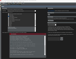
Test connection log
[Start: Blackhawk XDS560v2-USB System Trace Emulator_0]

Execute the command:

%ccs_base%/common/uscif/dbgjtag.exe -f %boarddatafile% -rv -o -F inform,logfile=yes -S pathlength -S integrity

[Result]


-----[Print the board config pathname(s)]------------------------------------

C:\Users\rhlchmao\AppData\Local\TEXASI~1\
    CCS\ccs1281\0\0\BrdDat\testBoard.dat

-----[Print the reset-command software log-file]-----------------------------

This utility has selected a 560/2xx-class product.
This utility will load the program 'bh560v2u.out'.
Loaded FPGA Image: C:\ti\ccs1281\ccs\ccs_base\common\uscif\dtc_top.jbc
The library build date was 'Sep 26 2024'.
The library build time was '10:02:16'.
The library package version is '20.0.0.3178'.
The library component version is '35.35.0.0'.
The controller does not use a programmable FPGA.

An error occurred while hard opening the controller.

-----[An error has occurred and this utility has aborted]--------------------

This error is generated by TI's USCIF driver or utilities.

The value is '-183' (0xffffff49).
The title is 'SC_ERR_CTL_CBL_BREAK_FAR'.

The explanation is:
The controller has detected a cable break far-from itself.
The user must connect the cable/pod to the target.

[End: Blackhawk XDS560v2-USB System Trace Emulator_0]
