This thread has been locked.

If you have a related question, please click the "Ask a related question" button in the top right corner. The newly created question will be automatically linked to this question.

J721EXCPXEVM: SPI TX will truncate the transmitted message.

Part Number: J721EXCPXEVM

Tool/software:

1. DUT: Device in use is the Jacinto J721e EVM carrier board with the GESI board extension.

2. Processor core: I'm developing on the mcu2_1 R5F core.

3. OS: I'm running RTOS for the OS.

4. SDK version: I am currently using only the SDK/PDK (ti-processor-sdk-rtos-j721e-evm-10_01_00_04) for my libraries and calls.

5. Hardware setup: I have SPI3 pins on the GESI board (J16 #13 - CLK; J5 #12 - D0, #4 - CS1) connected to an oscilloscope.

6. Software: I am attaching an example source code with which I can produce the problem. This has a .c file with the SPI setup and instructions; a CMakeLists.txt file is included to show you the build configuration.

Besides this running on mcu2_1 R5F, there's the sci server set up on mcu1_0.

#include <stdio.h>
#include <string.h>
#include <ti/osal/osal.h>
#include <ti/drv/sciclient/sciclient.h>

/* TI-RTOS Header files */
#include <ti/drv/spi/soc/SPI_soc.h>
#include <ti/drv/spi/src/SPI_osal.h>
#include <ti/drv/spi/SPI.h>

#include <ti/board/src/j721e_evm/include/board_utils.h>
#include <ti/csl/soc/j721e/src/cslr_soc_baseaddress.h>
#include <ti/csl/soc/j721e/src/cslr_wkup_ctrl_mmr.h>


/** \brief Application stack size */
#define APP_TSK_STACK_MAIN              (0x4000U)
/** \brief Task stack */
static uint8_t  gAppTskStackMain[APP_TSK_STACK_MAIN] __attribute__((aligned(32)));

/* Maximum # of channels per SPI instance */
#define MCSPI_MAX_NUM_CHN       4

/* SPI transfer message definitions */
#define SPI_MSG_LENGTH    8
#define SPI_WORD_SIZE_IN_BITS 8

#define SIZE_TOO_LARGE          (0x1FFFU)

#define MCSPI3_CONFIG_IDX       (3U)
#define MCSPI6_CONFIG_IDX       (6U)

#ifdef __cplusplus
extern "C" {
#endif //__cplusplus

extern void UART_printf(const char *pcString, ...);

#ifdef __cplusplus
}
#endif //__cplusplus

/* Callback mode variables */
SemaphoreP_Params cbSemParams;
SemaphoreP_Handle cbSem[MCSPI_MAX_NUM_CHN] = {NULL, NULL, NULL, NULL};

unsigned char masterRxBuffer[128] __attribute__ ((aligned (128)));
unsigned char masterTxBuffer[128] __attribute__ ((aligned (128)));

void MCSPI_initSciclient()
{
    int32_t ret = CSL_PASS;
    Sciclient_ConfigPrms_t        config;

    /* Now reinitialize it as default parameter */
    ret = Sciclient_configPrmsInit(&config);
    if (CSL_PASS != ret)
    {
        UART_printf("Sciclient_configPrmsInit Failed\n");
    }
    else if (CSL_PASS == ret)
    {
        ret = Sciclient_init(&config);
        if (CSL_PASS != ret)
        {
            UART_printf("Sciclient_init Failed\n");
        }
    }
}

/* Callback mode functions */
// NOT CURRENTLY USED
void SPI_callback(SPI_Handle handle, SPI_Transaction *transaction)
{
    UART_printf("SPI callback data size: %d\n", transaction->count);
    if (transaction->count > SIZE_TOO_LARGE)
    {
        SemaphoreP_post(cbSem[0]);
        return;
    }

    // uint8_t numToCopy = transaction->count * (SPI_WORD_SIZE_IN_BITS / 8);
    // CircularBuffer_write(&g_rxbuffer, reinterpret_cast<uint8_t*>(transaction->rxBuf), numToCopy);
    SemaphoreP_post(cbSem[0]);
}

void spi_test_master(void *arg0, void *arg1)
{
    UART_printf("Starting SPI Master test. \n");
    TaskP_sleepInMsecs(1000);
    uint32_t  terminateXfer = 1;

    SPI_init();

    // == Set up the SPI test for receive ==
    SPI_Handle        spi;
    SPI_Params        spiParams;
    // Note: master is false, pollmode is false, cbmode is true, timeout should be SemaphoreP_WAIT_FOREVER

    // Creates a callback semaphore
    SPI_osalSemParamsInit(&cbSemParams);
    cbSemParams.mode = SemaphoreP_Mode_BINARY;
    cbSem[0] = SPI_osalCreateBlockingLock(0, &cbSemParams);

    uint32_t instance = MCSPI3_CONFIG_IDX; //SPI_test_get_instance(2, false);
    uint32_t domain = SPI_MCSPI_DOMAIN_MAIN; //SPI_test_get_domain(2, false);

    // SPI_initConfig(domain, instance, test, MCSPI_TEST_CHN, BFALSE); --> expanded below
    MCSPI_socInit();

    SPI_HWAttrs spi_cfg;
    SPI_socGetInitCfg(domain, instance, &spi_cfg);
    spi_cfg.enableIntr = BFALSE; // BTRUE;
    spi_cfg.edmaHandle = NULL;
    spi_cfg.dmaMode    = BFALSE;

    /* Set the SPI init configurations */
    spi_cfg.chNum = 1;
    spi_cfg.chnCfg[1].dataLineCommMode = MCSPI_DATA_LINE_COMM_MODE_6;
    spi_cfg.chnCfg[1].tcs = MCSPI_CS_TCS_0PNT5_CLK;
    spi_cfg.chnCfg[1].trMode = MCSPI_TX_ONLY_MODE; //MCSPI_TX_RX_MODE;


    /* Set interrupt path */
    if(CSL_PASS != MCSPI_configSocIntrPath(instance, &spi_cfg, BTRUE))
    {
        UART_printf("\n Set interrupt path failed! Interrupt number %d\n", spi_cfg.intNum);
    }
    else
    {
        UART_printf("\n The interrupt path has been set with interrupt number %d\n", spi_cfg.intNum);
    }

    /* Set the SPI init configurations */
    SPI_socSetInitCfg(domain, instance, &spi_cfg);

    /* Initialize SPI handle */
    SPI_Params_init(&spiParams);
    spiParams.mode = SPI_MASTER;
    spiParams.transferMode = SPI_MODE_BLOCKING; // SPI_MODE_CALLBACK;
    // spiParams.transferCallbackFxn = SPI_callback;
    spiParams.transferTimeout = SemaphoreP_WAIT_FOREVER;
    spiParams.frameFormat = SPI_POL1_PHA0;
    spiParams.dataSize = 8U; // 8 bits
    spiParams.bitRate = 153600; // 153.6kHz

    spi = SPI_open(domain, instance, &spiParams);

    if (NULL == spi)
    {
        UART_printf("Error initializing SPI\n");
        return;
    }

    uint32_t xfer_len = SPI_MSG_LENGTH;

    Osal_delay(500);

    // Attempt a transfer
    uintptr_t addrMasterTxBuf = (uintptr_t)masterTxBuffer;
    uintptr_t addrMasterRxBuf = (uintptr_t)masterRxBuffer;
    bool transferOK = true;

    memset(masterRxBuffer, 0, sizeof(masterRxBuffer));
    memset(masterTxBuffer, 0, sizeof(masterTxBuffer));

    memcpy(masterTxBuffer, "TEST1234", 8);
    
    while (1)
    {
        SPI_Transaction   transaction;
        transaction.count = xfer_len;
        transaction.arg = (void *)&terminateXfer;
        transaction.txBuf = (void *)addrMasterTxBuf;
        transaction.rxBuf = (void *)addrMasterRxBuf;

        transferOK = SPI_transfer((SPI_Handle)spi, &transaction);
        if (!transferOK)
        {
            UART_printf("Error in SPI transfer\n");
        }
        else
        {   
            UART_printf("SPI transfer successful.\n");
        }
        Osal_delay(1000);
    }
}

/*
 *  ======== main ========
 */
 int main(void)
 {
    UART_printf("[UART] spi_test main()\n");

    /*  This should be called before any other OS calls (like Task creation, OS_start, etc..) */
    OS_init();

    /* Call board init functions */
    Board_initCfg boardCfg;
    Board_STATUS  boardStatus;

    /* Initialize the task params */
    TaskP_Params taskParams;
    TaskP_Params_init(&taskParams);

    /* Set the task priority higher than the default priority (1) */
    taskParams.priority     = 2;
    taskParams.stack        = gAppTskStackMain;
    taskParams.stacksize    = sizeof (gAppTskStackMain);

    TaskP_Params taskDataProcess;
    TaskP_Params_init(&taskDataProcess);
    
    TaskP_create(&spi_test_master, &taskParams);

    // If we run on MCU1_0, we need to setup the SciServer
    // For now, we will set up for MCU2_0, which uses a sciclient
    MCSPI_initSciclient();

    Board_PinmuxConfig_t boardPinmuxCfg;
    Board_pinmuxGetCfg(&boardPinmuxCfg);
    // boardPinmuxCfg.autoCfg = BOARD_PINMUX_AUTO;
    boardPinmuxCfg.gesiExp = BOARD_PINMUX_GESI_ICSSG;
    Board_pinmuxSetCfg(&boardPinmuxCfg);

    boardCfg = BOARD_INIT_PINMUX_CONFIG |
               BOARD_INIT_MODULE_CLOCK  |
               BOARD_INIT_UART_STDIO |
               BOARD_INIT_MODULE_CLOCK_MAIN;
    boardStatus = Board_init(boardCfg);

    /* Unlock lock key registers for Partition 1 */
    /* write Partition Lock Key 0 Register */
    CSL_REG32_WR(CSL_MCU_CTRL_MMR0_CFG0_BASE + CSL_MCU_CTRL_MMR_CFG0_LOCK1_KICK0, 0x68EF3490);
    /* write Partition Lock Key 1 Register */
    CSL_REG32_WR(CSL_MCU_CTRL_MMR0_CFG0_BASE + CSL_MCU_CTRL_MMR_CFG0_LOCK1_KICK1, 0xD172BC5A);
    /* Check for unlock */
    uint32_t regVal = CSL_REG32_RD(CSL_MCU_CTRL_MMR0_CFG0_BASE + CSL_MCU_CTRL_MMR_CFG0_LOCK1_KICK0);
    while ((regVal & 0x1) != 0x1U)
    {
        regVal = CSL_REG32_RD(CSL_MCU_CTRL_MMR0_CFG0_BASE + CSL_MCU_CTRL_MMR_CFG0_LOCK1_KICK0);
    }

    /* Enable MCU_MCSPI1 and MCSPI3 independently pin out */
    CSL_REG32_WR(CSL_MCU_CTRL_MMR0_CFG0_BASE +
        CSL_MCU_CTRL_MMR_CFG0_MCU_SPI1_CTRL,
            CSL_MCU_CTRL_MMR_CFG0_MCU_SPI1_CTRL_SPI1_LINKDIS_MASK);
//    *((uint32_t*)(0x40F04060)) = 1;

    // Creates a callback semaphore
    SemaphoreP_Params_init(&cbSemParams);
    cbSemParams.mode = SemaphoreP_Mode_BINARY;
    cbSem[0] = SemaphoreP_create(0, &cbSemParams);

    /* Start the scheduler to start the tasks executing. */
    OS_start();
 }
cmake_minimum_required(VERSION 3.24)

# Set the project name and version
project(spitx VERSION 1.0)

# Use debug or release libs
if(CMAKE_BUILD_TYPE STREQUAL "Release")
    set(BUILD_PROFILE "release")
else()
    set(BUILD_PROFILE "debug")
endif()

if(NOT DEFINED BOARD)
    set(BOARD "j721e_evm")
endif()

# Set the target processor
if(NOT DEFINED TARGET_PROCESSOR)
    set(TARGET_PROCESSOR "r5f")  # Modify this according to your target processor (R5F or A72, etc.)
elseif(NOT "${TARGET_PROCESSOR}" STREQUAL "r5f")
    message(FATAL_ERROR "TARGET_PROCESSOR=${TARGET_PROCESSOR} is not supported for this project.")
endif()

# Set the target core
# mcu1_0 mcu1_1 are no longer supported
set(SUPPORTED_CORES mcu2_0 mcu2_1)
if(NOT DEFINED TARGET_CORE)
    set(TARGET_CORE "mcu2_1")
elseif(NOT "${TARGET_CORE}" IN_LIST SUPPORTED_CORES)
    message(FATAL_ERROR "TARGET_CORE=${TARGET_CORE} not in supported core list.")
endif()

# Append to additional build options
if("${TARGET_CORE}" STREQUAL "mcu2_0")
    set(ADDITIONAL_BUILD_OPTS "${ADDITIONAL_BUILD_OPTS} -DBUILD_MCU2_0 -DBUILD_MCU")
elseif("${TARGET_CORE}" STREQUAL "mcu2_1")
    set(ADDITIONAL_BUILD_OPTS "${ADDITIONAL_BUILD_OPTS} -DBUILD_MCU2_1 -DBUILD_MCU")
endif()

# Specify the C compiler and flags
set(CMAKE_C_COMPILER "$ENV{TI_TOOLCHAIN_PATH}/bin/tiarmclang")
set(CMAKE_CXX_COMPILER "$ENV{TI_TOOLCHAIN_PATH}/bin/tiarmclang")
set(CMAKE_LINKER "$ENV{TI_TOOLCHAIN_PATH}/bin/tiarmclang")
set(LIBC_AR "$ENV{TI_TOOLCHAIN_PATH}/lib/libc.a") 

# Specify the C flags (e.g., optimization, architecture)
set(CMAKE_C_FLAGS "-g -DMAKEFILE_BUILD -fno-strict-aliasing -EL -mfloat-abi=hard -mfpu=vfpv3-d16 -mcpu=cortex-r5 -mthumb -march=thumbv7r -DFREERTOS -DSOC_J721E -Dj721e_evm=j721e_evm ${ADDITIONAL_BUILD_OPTS}")
set(CMAKE_CXX_FLAGS "-DMAKEFILE_BUILD -fno-strict-aliasing -EL -mfloat-abi=hard -mfpu=vfpv3-d16 -mcpu=cortex-r5 -mthumb -march=thumbv7r -DFREERTOS -DSOC_J721E -Dj721e_evm=j721e_evm ${ADDITIONAL_BUILD_OPTS}")

# Set PDK_SOURCE_DIR
if(NOT DEFINED PDK_SOURCE_DIR)
    set(PDK_SOURCE_DIR "$ENV{TI_SDK_PATH}/pdk_jacinto_10_01_00_25")
endif()

set(SPI_LIB "${CMAKE_SOURCE_DIR}/lib/${BUILD_PROFILE}/wx.spi.aer5f")

# Add the include directories for Processor SDK and PDK
include_directories(
    ${PDK_SOURCE_DIR}/packages
    ${CMAKE_CURRENT_SOURCE_DIR}
    ${CMAKE_SOURCE_DIR}/board/src/
    ${CMAKE_SOURCE_DIR}/board/src/j721e_evm/include
    ${CMAKE_CURRENT_SOURCE_DIR}/src/
    ${PDK_SOURCE_DIR}/packages/ti/csl/
    ${PDK_SOURCE_DIR}/packages/ti/csl/arch/r5/
    ${PDK_SOURCE_DIR}/packages/ti/csl/arch/r5/src/startup/
    ${PDK_SOURCE_DIR}/packages/ti/kernel/freertos/config/j721e/r5f/
)

if("${TARGET_CORE}" STREQUAL "mcu2_0" OR "${TARGET_CORE}" STREQUAL "mcu2_1")
    set(ADDITIONAL_LIBS
        "${PDK_SOURCE_DIR}/packages/ti/build/j721e/linker_r5_freertos.lds"
    )
else()
    message(FATAL_ERROR "Core not yet supported.")
endif()

# Add the source files
set(SOURCES
    ${CMAKE_CURRENT_SOURCE_DIR}/main.c
)

# Add the source to the executable
add_executable(${PROJECT_NAME} ${SOURCES})

set(GROUPED_LIBS 
    "${PDK_SOURCE_DIR}/packages/ti/csl/lib/j721e/${TARGET_PROCESSOR}/${BUILD_PROFILE}/ti.csl.aer5f"
    "${PDK_SOURCE_DIR}/packages/ti/drv/uart/lib/j721e/${TARGET_PROCESSOR}/${BUILD_PROFILE}/ti.drv.uart.aer5f"
    "${PDK_SOURCE_DIR}/packages/ti/drv/i2c/lib/j721e/${TARGET_PROCESSOR}/${BUILD_PROFILE}/ti.drv.i2c.aer5f"
    "${PDK_SOURCE_DIR}/packages/ti/drv/udma/lib/j721e/${TARGET_CORE}/${BUILD_PROFILE}/udma.aer5f"
    "${PDK_SOURCE_DIR}/packages/ti/drv/gpio/lib/j721e/${TARGET_PROCESSOR}/${BUILD_PROFILE}/ti.drv.gpio.aer5f"
    "${PDK_SOURCE_DIR}/packages/ti/drv/pmic/lib/j721e_evm/${TARGET_PROCESSOR}/${BUILD_PROFILE}/pmic.aer5f"
    "${PDK_SOURCE_DIR}/packages/ti/drv/pm/lib/j721e/${TARGET_PROCESSOR}/${BUILD_PROFILE}/pm_lib.aer5f"
    "${PDK_SOURCE_DIR}/packages/ti/board/lib/j721e_evm/${TARGET_PROCESSOR}/${BUILD_PROFILE}/ti.board.aer5f"
    "${PDK_SOURCE_DIR}/packages/ti/drv/sciclient/lib/j721e/${TARGET_CORE}/${BUILD_PROFILE}/sciclient.aer5f"
    "${PDK_SOURCE_DIR}/packages/ti/osal/lib/freertos/j721e/${TARGET_PROCESSOR}/${BUILD_PROFILE}/ti.osal.aer5f"
    "${PDK_SOURCE_DIR}/packages/ti/kernel/lib/j721e/${TARGET_CORE}/${BUILD_PROFILE}/ti.kernel.freertos.aer5f"
    "${PDK_SOURCE_DIR}/packages/ti/csl/lib/j721e/${TARGET_PROCESSOR}/${BUILD_PROFILE}/ti.csl.init.aer5f"
    "${PDK_SOURCE_DIR}/packages/ti/drv/spi/lib/j721e/r5f/${BUILD_PROFILE}/ti.drv.spi.aer5f"
    "${LIBC_AR}"
)

# Link the necessary libraries (adjust paths to your SDK)
target_link_libraries(${PROJECT_NAME}
    "${ADDITIONAL_LIBS}"
    $<LINK_GROUP:RESCAN, ${GROUPED_LIBS}>
)

# Define the required linker flags (for linking in startup files, etc.)
target_link_options(${PROJECT_NAME} PRIVATE 
    -Werror 
    -Wl,-q 
    -Wl,-u,_c_int00 
    -Wl,--display_error_number 
    -Wl,--use_memcpy=fast 
    -Wl,--use_memset=fast 
    -Wl,--diag_suppress=10063-D 
    -Wl,--diag_suppress=10068-D 
    -Wl,--diag_suppress=10083-D 
    -Wl,-c 
    -mcpu=cortex-r5 
    -march=armv7-r 
    -Wl,--diag_suppress=10230-D  
    -Wl,-x 
    -Wl,--zero_init=on
)

# Set the output directory
set(EXECUTABLE_OUTPUT_PATH ${CMAKE_BINARY_DIR}/bin)

# Set the post-build commands (e.g., copy binaries to specific folder)
add_custom_command(TARGET ${PROJECT_NAME} POST_BUILD
    COMMAND ${CMAKE_COMMAND} -E copy ${EXECUTABLE_OUTPUT_PATH}/${PROJECT_NAME} ${CMAKE_SOURCE_DIR}/bin/${BUILD_PROFILE}/${PROJECT_NAME}_${TARGET_PROCESSOR}_${TARGET_CORE}.xer5f
)

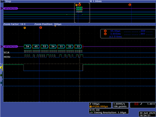
7. Expected behavior: It should transmit the number of bytes that I pass to transaction.count.

8. What does happen: It does not. In this case, it's truncating the message by a byte. Other code elsewhere gets the last five or for longer messages, the last fifteen chopped off.

9. Other boards: I have not yet tested on other boards.

10. Frequency: Happens every time I load a new image.

11. Diagnosis/debugging: I've tried changing the size of the message, truncation happens at any size. Changing the transaction.count does increase it, but if I send a 64 byte message, seems silly to tell it that it really is a 65 byte. In other code, this (the size) isn't always as predictable (sending the entire buffer of 128 bytes resulted in 113 bytes only being sent).

12. Logs, etc.

O-Scope output for this:

SPI3 registers:

521177 13
R MCSPI3_CFG_MCSPI_HL_REV 0x0000000B 0x40301A0B
R MCSPI3_CFG_MCSPI_HL_HWINFO 0x0000000B 0x00000009
R MCSPI3_CFG_MCSPI_HL_SYSCONFIG 0x0000000B 0x00000004
R MCSPI3_CFG_MCSPI_REVISION 0x0000000B 0x0000002B
R MCSPI3_CFG_MCSPI_SYSCONFIG 0x0000000B 0x00000308
R MCSPI3_CFG_MCSPI_SYSSTATUS 0x0000000B 0x00000001
R MCSPI3_CFG_MCSPI_IRQSTATUS 0x0000000B 0x00000010
R MCSPI3_CFG_MCSPI_IRQENABLE 0x0000000B 0x00000000
R MCSPI3_CFG_MCSPI_WAKEUPENABLE 0x0000000B 0x00000000
R MCSPI3_CFG_MCSPI_SYST 0x0000000B 0x00000000
R MCSPI3_CFG_MCSPI_MODULCTRL 0x0000000B 0x00000001
R MCSPI3_CFG_MCSPI_CHCONF_0 0x0000000B 0x00060000
R MCSPI3_CFG_MCSPI_CHSTAT_0 0x0000000B 0x00000000
R MCSPI3_CFG_MCSPI_CHCTRL_0 0x0000000B 0x00000000
R MCSPI3_CFG_MCSPI_TX_0 0x0000000B 0x00000000
R MCSPI3_CFG_MCSPI_RX_0 0x0000000B 0x00000000
R MCSPI3_CFG_MCSPI_CHCONF_1 0x0000000B 0x200623D0
R MCSPI3_CFG_MCSPI_CHSTAT_1 0x0000000B 0x00000004
R MCSPI3_CFG_MCSPI_CHCTRL_1 0x0000000B 0x00001401
R MCSPI3_CFG_MCSPI_TX_1 0x0000000B 0x00000034
R MCSPI3_CFG_MCSPI_RX_1 0x0000000B 0xFFFFFFFF
R MCSPI3_CFG_MCSPI_CHCONF_2 0x0000000B 0x00060000
R MCSPI3_CFG_MCSPI_CHSTAT_2 0x0000000B 0x00000000
R MCSPI3_CFG_MCSPI_CHCTRL_2 0x0000000B 0x00000000
R MCSPI3_CFG_MCSPI_TX_2 0x0000000B 0x00000000
R MCSPI3_CFG_MCSPI_RX_2 0x0000000B 0x00000000
R MCSPI3_CFG_MCSPI_CHCONF_3 0x0000000B 0x00060000
R MCSPI3_CFG_MCSPI_CHSTAT_3 0x0000000B 0x00000000
R MCSPI3_CFG_MCSPI_CHCTRL_3 0x0000000B 0x00000000
R MCSPI3_CFG_MCSPI_TX_3 0x0000000B 0x00000000
R MCSPI3_CFG_MCSPI_RX_3 0x0000000B 0x00000000
R MCSPI3_CFG_MCSPI_XFERLEVEL 0x0000000B 0x00080007
R MCSPI3_CFG_MCSPI_DAFTX 0x0000000B 0x00000000
R MCSPI3_CFG_MCSPI_DAFRX 0x0000000B 0x00000000

  • Hello,

    In the thread 

    https://e2e.ti.com/support/processors-group/processors/f/processors-forum/1526811/j721exsomxevm-transmitting-data-over-spi3-and-spi6-only-transmits-one-byte

    You mentioned all the Tx related issues has been solved for SPI3 and SPI6. Right ? what changed now?

    Regards

    Tarun Mukesh

  • You mentioned all the Tx related issues has been solved for SPI3 and SPI6. Right ?

    Solved for transmitting more than one byte, but there's several other issues that went unanswered.

    • Why does enabling FIFO only transmit one byte, even if we have the right chip select?
    • There is still some kind of event, interrupt, or similar that cuts off the message. What is doing this?
    • Why doesn't callback get called in callback mode?

    In lieu of answers for those questions, I've moved on.

    what changed now?

    I am now transmitting more bytes, and noticed the short-changing. I have also moved to channel 1 with CS1, because chip select is indeed necessary.

  • Here is something I've observed: I've started debugging, rebuilt the libraries for debug (modified optimization with -O0) otherwise a lot of stuff gets optimized out. I found by placing a breakpoint at line 901 of SPI_v1.c (ti-processor-sdk-rtos-j721e-evm-10_01_00_04/pdk_jacinto_10_01_00_25/packages/ti/drv/spi/src/v1/SPI_v1.c)

            if ((SPI_MASTER      == chObj->spiParams.mode) &&
                (MCSPI_SINGLE_CH == hwAttrs->chMode))
            {
                /* Force SPIEN line to the inactive state.*/
                McSPICSDeAssert(hwAttrs->baseAddr, chNum);
            }

    and continuing will print out the entire message, with or without FIFO enabled. I modified this code and commented out the "McSPICSDeAssert" line and tried without the breakpoint, and it prints out the entire message.

    Something with putting the SPIEN to an inactive state is truncating these messages! Why does this truncate the messages, and is there a workaround?

  • Hello,

    You can use interrupt mode , right ?

    In interrupt mode, master driver enables TX empty, RX full and end of word count interrupts. slave driver enables RX full interrupt. The TX/RX data are handled in the ISR.
    In polling mode, master driver continuously writes 1 byte TX data to TX FIFO followed by reading 1 byte RX data from the RX FIFO until all the data are transferred. slave driver continuously reads 1 byte data from the RX FIFO followed by writing 1 byte TX data to TX FIFO until all the data are transferred.
    Something with putting the SPIEN to an inactive state is truncating these messages!

    Obviously if you inactive the SPIEN then transmission will not happen at that time that's basic SPI protocol. After full transmission only this deassert will be called.

    In Interrupt mode it will ensure the Deassert is called in ISR and after complete transmission only this will be called without truncating data. 

    and continuing will print out the entire message, with or without FIFO enabled. I modified this code and commented out the "McSPICSDeAssert" line and tried without the breakpoint, and it prints out the entire message.

    Something with putting the SPIEN to an inactive state is truncating these messages! Why does this truncate the messages, and is there a workaround?

    This underlines that you are facing timing issue and Deassert is happening before the transmission is successfully done.So ensure the Deassert happens after the whole message is transmitted.
    Regards
    Tarun Mukesh
  • In Interrupt mode it will ensure the Deassert is called in ISR and after complete transmission only this will be called without truncating data. 

    All right, this makes sense. Strangely, enabling interrupts introduces a complication...I can't get the interrupts working. Again.

        SPI_HWAttrs spi_cfg;
        SPI_socGetInitCfg(domain, instance, &spi_cfg);
        spi_cfg.enableIntr = BTRUE;
        spi_cfg.edmaHandle = NULL;
        spi_cfg.dmaMode    = BFALSE;
        // spi_cfg.intNum     = CSLR_COMPUTE_CLUSTER0_GIC500SS_SPI_MCSPI3_INTR_SPI_0;
        // spi_cfg.intNum     = CSLR_R5FSS0_INTROUTER0_IN_MCSPI3_INTR_SPI_0;
        // What should the intNum be??
    
    
        /* Set the SPI init configurations */
        spi_cfg.chNum = 0;
        spi_cfg.chnCfg[0].dataLineCommMode = MCSPI_DATA_LINE_COMM_MODE_6;
        spi_cfg.chnCfg[0].tcs = MCSPI_CS_TCS_0PNT5_CLK;
        spi_cfg.chnCfg[0].trMode = MCSPI_TX_ONLY_MODE; 
        spi_cfg.chnCfg[0].enableFIFO = 1; // Tried both 0 and 1; neither affects the interrupt
    
        /* Set interrupt path */
        if(CSL_PASS != MCSPI_configSocIntrPath(instance, &spi_cfg, BTRUE))
        {
            UART_printf("\n Set interrupt path failed! Interrupt number %d\n", spi_cfg.intNum);
        }
        else
        {
            UART_printf("\n The interrupt path has been set with interrupt number %d\n", spi_cfg.intNum);
        }

    I know in a previous post of mine, I thought I understood it, but I don't think I am. Tried various interrupt numbers as you see above. 

  • Hello,

    There shouldn't be any change from previous.

    All right, this makes sense. Strangely, enabling interrupts introduces a complication...I can't get the interrupts working. Again.

    what changed again from previous ?

    Even for 1 byte if you get the same should continue for other.

    You can also check MCAL example of MCSPI3 configured on MCU2_1.They are using 258 irq number

    for (idx = 0U; idx < cfgPtr->maxHwUnit; idx++)
        {
            if (cfgPtr->hwUnitCfg[idx].enabledmaMode == FALSE)
            {
                rmIrqReq.valid_params           = TISCI_MSG_VALUE_RM_DST_ID_VALID;
                rmIrqReq.valid_params          |= TISCI_MSG_VALUE_RM_DST_HOST_IRQ_VALID;
                rmIrqReq.src_id                 = TISCI_DEV_MCSPI3;
                rmIrqReq.global_event           = 0U;
                rmIrqReq.src_index              = 0U;
                rmIrqReq.dst_id                 = TISCI_DEV_R5FSS0_CORE1;
                rmIrqReq.dst_host_irq           = APP_SPI_3_INT;
                rmIrqReq.ia_id                  = 0U;
                rmIrqReq.vint                   = 0U;
                rmIrqReq.vint_status_bit_index  = 0U;
                rmIrqReq.secondary_host         = TISCI_MSG_VALUE_RM_UNUSED_SECONDARY_HOST;
                retVal = Sciclient_rmIrqSet(
                             &rmIrqReq, &rmIrqResp, APP_SCICLIENT_TIMEOUT);
                if(LLD_PASS != retVal)
                {
                    AppUtils_Printf(APP_UTILS_PRINT_MSG_NORMAL,
                        "Error in SciClient Interrupt Params Configuration!!!\n");
                }
                Osal_RegisterInterrupt_initParams(&intrPrms);
            #if (STD_ON == SPI_UNIT_MCSPI3_ACTIVE)
            #if (SPI_ISR_TYPE == SPI_ISR_CAT1 || SPI_ISR_TYPE == SPI_ISR_VOID)
                intrPrms.corepacConfig.arg          = (uintptr_t)Spi_IrqUnitMcspi3TxRx;
            #endif
            #endif
                intrPrms.corepacConfig.isrRoutine   = &SpiApp_SpiXIsr;
                intrPrms.corepacConfig.priority     = 1U;
                intrPrms.corepacConfig.corepacEventNum = 0U; /* NOT USED ? */
                intrPrms.corepacConfig.intVecNum        = APP_SPI_3_INT;
    
                osalRetVal = Osal_RegisterInterrupt(&intrPrms, &hwiHandle);
                if(OSAL_INT_SUCCESS != osalRetVal)
                {
                    AppUtils_Printf(APP_UTILS_PRINT_MSG_NORMAL,
                                      ": Error %d !!!\n");
                }
            }

    Regards

    Tarun Mukesh

  • So get this: no code change, but I did reset every core instead of just the mcu2_1 core I was working on. It works suddenly.

    I'm wondering if something with the sciserver got in a bad state and any further requests to register or unregister the interrupt just wouldn't work. Can't say I understand the workings of it well.

    But provided that the interrupts are set up correctly, I am currently seeing the entire message come through. I'll be testing with a larger message here in a bit.

    Edit: Tried with a message of 43 bytes, and I'm setting transaction.count to this size too. I'm not getting the interrupt. Tried back and forth, making sure to restart the sciserver everytime.

    24 bytes: working.

    31 bytes: working.

    32 bytes: working.

    33 bytes: not working.

    40 (or anything above 32 bytes): not working.

    Interesting. So sending something larger than 32 bytes is a no-go; is this because of MCSPI_RX_TX_FIFO_SIZE? I thought it would use MCSPI_FULL_FIFO_SIZE if we're doing a Tx only mode. And, not using FIFO for this doesn't work in any case. So what is the cause of this 32 byte limit?

    If I'm slow to respond in the next few days, it's because I'll be out of the office until Monday.

  • Hello,

    I'm wondering if something with the sciserver got in a bad state and any further requests to register or unregister the interrupt just wouldn't work. Can't say I understand the workings of it well.

    But provided that the interrupts are set up correctly, I am currently seeing the entire message come through. I'll be testing with a larger message here in a bit.

    secure sciclient calls go through M3/M4 cores, if you don't reset the soc and only reset MCU2_1 core and try to do interrupt routing it will fail.

    Your interrupt routing understanding is correct but it is system flow which you are not aware.

    Try soc reset for different lengths of transactions. 

    We need to inspect the below register details now

    R MCSPI3_CFG_MCSPI_XFERLEVEL 

    Using McSPIFIFOTrigLvlSet API we will set the trigger level and followed we will set the word count.

    If you are using the TX_ONLY_MODE the trigger level of AEL should be set to (64-1)

    Followed by transaction count into Word count  by McSPIWordCountSet API.

    RegardS

    Tarun Mukesh

  • R MCSPI3_CFG_MCSPI_XFERLEVEL 

    Hmm, odd. AEL is set to 0x17 when I checked on a 32-byte message. Not sure how that is calculated.

    I went back to tracing the logic in SPI_v1.c for a 43-byte message. Looking at where it uses those API calls to set the trigger and word count. If I set the word size to 16 bits, I do see for the final byte that the XFERLEVEL gets set to 0x0A, which I think makes sense (43 byte message - 32 FIFO size(?) - 1). And with that word size, the entire 43 bytes do get through.

    So yeah, I'm not sure if the trigger level is getting set to 64, I'll be looking a little closer as to why that's not happening.

  • Hello,

    Hmm, odd. AEL is set to 0x17 when I checked on a 32-byte message. Not sure how that is calculated.

    I went back to tracing the logic in SPI_v1.c for a 43-byte message. Looking at where it uses those API calls to set the trigger and word count. If I set the word size to 16 bits, I do see for the final byte that the XFERLEVEL gets set to 0x0A, which I think makes sense (43 byte message - 32 FIFO size(?) - 1). And with that word size, the entire 43 bytes do get through.

    So yeah, I'm not sure if the trigger level is getting set to 64, I'll be looking a little closer as to why that's not happening.

    Yes please check. Unless you set the trigger level AEL correctly you might miss out some ot the bytes.

    Regards

    Tarun Mukesh

  • Okay, for this 43-byte message, I can set the txTrigLvl to a higher number, say 48, and it will send the entire message with a dataSize of 8U.  And I'm testing with a 23-byte message, don't have to change configuration, and it works. 7-byte message, it seems to be working.

    The complication comes in when I try to integrate this into another application using SPI6 as well for RX. And I get it, the question to ask is what is different between the two? For example, I couldn't get the TX interrupt working on the app unless I set up the TX before the RX interrupts. 

    Funny enough, I've recently decided to dive in fully to the project I'm working on that uses both SPIs, although unconventionally used. I was shocked how flawlessly it worked suddenly, and I'm left scratching my head wondering how this is all working better as unconventional use of SPI when I was struggling to get the device working as a SPI in the first place in these simpler demos. Oh well.

    I'm not sure what in the driver originally was forcing the txTrigLvl to be 32, but if you force it to be larger (48, 64...) it seems to work great.

  • Hello Tyler,

    Funny enough, I've recently decided to dive in fully to the project I'm working on that uses both SPIs, although unconventionally used. I was shocked how flawlessly it worked suddenly, and I'm left scratching my head wondering how this is all working better as unconventional use of SPI when I was struggling to get the device working as a SPI in the first place in these simpler demos. Oh well.

    I'm not sure what in the driver originally was forcing the txTrigLvl to be 32, but if you force it to be larger (48, 64...) it seems to work great.

    I don't think there is any flaw in driver , it can be due to some other issues. If driver runs freely without halting and corruption then it will allocate the txTrigLvl correctly and will not have any problem.

    The complication comes in when I try to integrate this into another application using SPI6 as well for RX. And I get it, the question to ask is what is different between the two? For example, I couldn't get the TX interrupt working on the app unless I set up the TX before the RX interrupts. 

    The order of enabling SPI TX and RX interrupts can impact the behavior of your application, particularly if you're experiencing issues with the TX interrupt not working correctly. 

    If the RX interrupt is enabled and triggered before the TX interrupt setup is complete, it could lead to data corruption or unexpected behavior

    Ensuring the TX interrupt is fully configured and enabled before the RX interrupt is crucial for proper SPI communication, especially in scenarios involving simultaneous bidirectional communication or when the slave device needs to send data in response to a master request.

    Regards

    Tarun Mukesh