TMDS64EVM: How to use WDT in microsecond order

Part Number: TMDS64EVM
Other Parts Discussed in Thread: AM6442, SYSCONFIG

Tool/software:

Hello TI support team.

I have a question about the WDT for AM6442 CR5.
I am using mcu_plus_sdk_am64x_08_06_00_45 as the SDK.
I would like to use the WDT in microsec order rather than millisec order.
For example, I would like to clear the WDT every 50us.

Looking at the API's Watchdog_Params, there is the following parameter:
"uint32_t Watchdog_Params::expirationTime"
This unit is milliseconds, but could you please tell me how to set it in microseconds?
Also, please let me know if there is any sample code for resetting the CPU with the WDT.

Best regards,
Kiyomasa Imaizumi.

  • Additional note.

    Is it possible to use the WDT with the PRU?

    I am also considering clearing the WDT at the timing of the iep timer's us order.

    If there is any PRU sample code for this as well, please let me know.

    Best regards,

    Kiyomasa Imaizumi.

  • Hello Kiyomasa Imaizumi,

    I am looking at your queries and you may expect reply in one or two days .

    Regards,

    Anil.

  • Understanding the Watchdog Mechanism

    The watchdog timers in the ICSS IEP are designed to monitor system stability. When enabled, they count down from a configured value, and if they reach zero (expire), they generate an event that can trigger corrective action. To prevent expiration, the watchdogs need to be regularly serviced.

    Steps to Trigger/Tick the ICSSG IEP PDI and PD Watchdog

    1. Configure the Watchdog Timers:

      • Set the PDI_WD_TIME value in the IEP_PDI_WD_TIM_REG register (0x3E8 or 1000 decimal by default)
      • Set the PD_WD_TIME value in the IEP_PD_WD_TIM_REG register
    2. Enable the Watchdog Timers:

      • Write to the WD_CTRL_REG (0x214):
        • Set bit 16 (pdi_wd_en) to 1 to enable PDI Watchdog
        • Set bit 0 (pd_wd_en) to 1 to enable PD Watchdog
    3. Service/Tick the Watchdog: While the documentation doesn't explicitly mention a dedicated "reload" or "service" register, there are two common approaches to servicing watchdogs in embedded systems:

      Method 1: Rewrite the Timer Value

      • Periodically write to the IEP_PDI_WD_TIM_REG and IEP_PD_WD_TIM_REG registers with the desired timeout value
      • This reloads the watchdog counter with the specified value, preventing expiration

      Method 2: Toggle Control Register

      • Periodically disable and re-enable the watchdog by toggling the enable bits in WD_CTRL_REG
      • First write 0 to the enable bit, then write 1 to restart the watchdog
    4. Monitor Watchdog Status:

      • Read the WD_STATUS_REG (0x20C) to check the status:
        • Bit 16 (pdi_wd_status): 1 = active or disabled, 0 = expired
        • Bit 0 (pd_wd_status): 1 = active or disabled, 0 = expired
    5. Clear Expiration Counters (if needed):

      • Write to the EXP_COUNTER_REG (0x210) to clear the expiration counters
      • Bits 7-0 (pdi_exp_cnt): Counts PDI watchdog timeouts
      • Bits 15-8 (pd_exp_cnt): Counts PD watchdog timeouts

    Important Notes

    1. The watchdog service operation should be performed at regular intervals that are shorter than the configured timeout period.

    2. For the PDI watchdog, if PRUSS_IEP_WD_PREDIV[15-0] PRE_DIV is set to 100μs, and PDI_WD_TIME is set to 0x03E8 (1000 decimal), the timeout period is 100ms.

    3. The documentation states that "if the system is stable, the watchdog timer should be regularly reset or cleared to avoid timeout or expiration," confirming that regular servicing is required.

  • Hello PratheeshGangadhar.

    Thank you for your reply.

    I also referred to 6.4.13.2.7 PRU_ICSSG IEP WatchDog in the TRM.

    I have a question.
    What is the difference between PD and PDI? Should I use PDI?

    Regarding "3.Service/Tick the Watchdog",
    if I do not use Method 1 or 2, will the AM64 be reset?

    Best regards,
    Kiyomasa Imaizumi.

  • What is the difference between PD and PDI? Should I use PDI?

    You can use either of them, PDI might be better.

    if I do not use Method 1 or 2, will the AM64 be reset?

    No, it won't AM64 reset needs to be managed in software, WD expiry status will be set in register, and software needs to act by initiating reset (+) PROCESSOR-SDK-AM64X: Triggering a system reset on AM64X - Processors forum - Processors - TI E2E support forums

  • Hello PratheeshGangadhar.

    Thank you for your reply.
    So, could you tell me about the microsecond-order WDT in CR5 that I asked about above?
    Looking at the Watchdog_Params API, there is the following parameter:
    "uint32_t Watchdog_Params::expirationTime"
    This is in milliseconds, but how can I set it to microseconds?
    For example, I want to clear the WDT every 50us.

    Best reagrds,
    Kiyomasa Imaizumi.

  • Hello PratheeshGangadhar and Swargam Anil.

    By changing the WDT fclk, I was able to achieve a 1ms WDT.

    If I want to perform a CPU reset, is it correct to rewrite CTRLMMR_RST_CTRL_REG as follows
    to perform a warm reset in the NMI interrupt that occurs when the WDT times out?

    ---
    #define CTRLMMR_RST_CTRL_REG (0x43018170) // Partition 6
    void watchdogCallback(void *arg)
    {
        ~~~
        // warm reset
        SOC_controlModuleUnlockMMR(SOC_DOMAIN_ID_MAIN, 6);
        unsigned long  n = *(volatile uint32_t*)(CTRLMMR_RST_CTRL_REG);
        n = (n & 0xfffffff0) | 0x06; // SW_MAIN_WARMRST b'0110
        *(volatile uint32_t*)(CTRLMMR_RST_CTRL_REG) = n;
    }
    ---

    I also understand that AM64 does not support the CPU reset function in WDT, and CPU reset must be performed by software.

    Best regards,
    Kiyomasa Imaizumi.
  • Hello Kiyomasa Imaizumi,

    The above suggested method does not work correctly, because it relies on controlling the RESET bits from within the WDT ISR routine .

    Problem Description:

    If the R5F core encounters an exception, it will jump to the exception handler and may remain stuck there indefinitely, preventing the main application from resuming normal execution.

    In such a case:
    • The Watchdog Timer (WDT) may expire, but
    • Its interrupt is treated as a normal IRQ, which is lower priority than the exception.
    • As a result, the WDT ISR may never get executed, and reset logic controlled from the ISR will not trigger, causing failure in expected system behavior.

    Recommended Solution:

    Use the ESM (Error Signaling Module) instead of relying on the WDT interrupt.
    • You should route the WDT expiration event to the ESM.
    • The ESM can be configured to generate a system reset based on the WDT event.
    • This is controlled using the ESM-to-WDT routing and CTRL_MMR configuration.

    This ensures that even if the core is stuck in an exception , the ESM module will force a reset reliably.

    Additional References:
    • Please refer to the FAQ  for more details on how to configure WDT → ESM → SOC Reset flow.
    • Also, look at  the attached Excel sheet which outlines the minimum/maximum timeout durations and resolutions that can be achieved for various clock frequencies used by the WDT. Just , change input clock from 32K to 25MHz Hz clock and see the Results .

    https://e2e.ti.com/support/processors-group/processors/f/processors-forum/1283237/faq-am64x-am62x-how-to-reset-the-soc-when-wdt-timer-expires-in-am64x-and-am62x

    /cfs-file/__key/communityserver-discussions-components-files/791/Watchdog.xlsx

    Regards,
    Anil.

  • Hello Swargam Anil.

    Thank you for your reply.

    I tried booting from RAM using "2068.WDG_Reset_AM64X.zip" from the link below.

    e2e.ti.com/.../faq-am64x-am62x-how-to-reset-the-soc-when-wdt-timer-expires-in-am64x-and-am62x

    However, the debug output stops at the following point.

    ---
    [MAIN_Cortex_R5_0_0]
    RTI Example Test Application

    RTI_Test_init: Init MAIN ESM complete

    RTI Example code UC-1 started
    DWWD configured to 100 percent window size
    DWWD is configured for 10000 ms time-out

    RTI DWWD proper servicing test running.
    Please wait for max 10000 ms.
    Wait for 10 sec for interrupt to be generated by DWWD.

    ---

    Even after waiting for more than 10 seconds, no DWWD interrupt was received.

    Does 2068.WDG_Reset_AM64X.zip work correctly?

    The SDK version used is 8.6.0.45. In the example, it was 8.6.0.43.

    Best regards,

    Kiyomasa Imaizumi.

  • Hello Kiyomasa Imaizumi,

    The above attached example will not generate an interrupt. Once the WDT expires, the SOC gets reset.

    After the WDT is expired, you need to check the SOC is Resetting or not by observing  the Boot log.

    Regards,

    Anil.


  • Hello Swargam Anil.

    I was able to confirm the reset after 10 seconds.
    Thank you.

    I think I should run the watchdog service within 10 seconds to avoid the reset.
    In that case, should I call the following function? (sdl_rti_example_uc1.c)
    RTIAppExpiredDwwdService()

    Or is the following enough?
    SDL_RTI_service(SDL_INSTANCE_RTI)

    Why does the RTIAppExpiredDwwdService function call SDL_RTI_service twice?

    Best regards,
    Kiyomasa Imaizumi.

  • Hello Swargam Anil.

    I am trying the CR5 WDT->ESM->SOC reset flow with the CR5 and CA53 programs running in ROM.
    The CR5's WDT is set to 32kHz, with a 10sec timeout to reset.
    However, after 10 seconds, although it seems that a reset has actually occurred, no reboot has occurred.
    After this reset, SBL OSPI does not start.

    I confirmed the circumstances under which a reboot does not occur.
    I am using OSPI Flash with CA53.
    When the Flash_open function is executed with CA53, the WDT->ESM->SOC reset of CR5 does not work properly and the system does not reboot.
    If the Flash_open function is not executed, the system reboots correctly.
    It seems that the call to Flash_open is the cause. (Flash_open function is flash.c)

    Do you know what the cause is? I'd like to resolve this as soon as possible.

    Best regards,
    Kiyomasa Imaizumi.

  • Additional note.

    After performing Flash_open on CA53, I performed Flash_reset on CA53 within 10 seconds before the WDT reset began, and it rebooted correctly.
    If the CA53 was left in Flash_open, it did not reboot when the CR5 WDT reset occurred.
    In fact, I use CA53 in Flash_open state.
    In this situation, how can I reboot correctly even if the CR5 WDT times out?

    Best regards,
    Kiyomasa Imaizumi.

  • Additional note.

    In the above case where the CR5 was unable to complete the WDT reset and did not reboot, I attached to the CR5 in CCS using the XDS110 debugger.

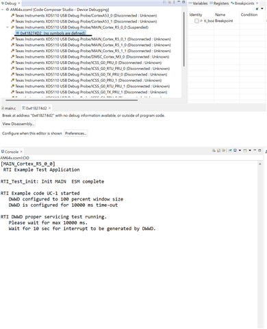
    As shown below, it pointed to an address that was not in the memory map of the CR5 project, such as 0x41822048.

    What happens if the WDT times out in CR5 while CA53 is in Flash_open state?

    Best regards,

    Kiyomasa Imaizumi.

  • I am trying the CR5 WDT->ESM->SOC reset flow with the CR5 and CA53 programs running in ROM.
    The CR5's WDT is set to 32kHz, with a 10sec timeout to reset.
    However, after 10 seconds, although it seems that a reset has actually occurred, no reboot has occurred.
    After this reset, SBL OSPI does not start.

    Hello Kiyomasa Imaizumi.

    There is no dependency on the Flash_Open API with the WDT functionality ...

    Can you please share your example project to review the code changes ?

    I am using OSPI Flash with CA53.

    Which means you are using the Flash Module in the A53 core ?

    Regards,

    Anil.

  • Hello Swargam Anil.


    I added flash functionality (Flash_Open) to the sample project (sdl_rti_example_uc1_am64x-evm_r5fss0-0_nortos_ti-arm-clang) that resets the CR5.
    I've attached the project.


    After Flash_Open, I expected the CR5 WDT->ESM->SOC to be reset 10 seconds later, but the SOC did not reset. (I'm trying to boot from RAM using the XDS110.)

    My program uses Flash in CA53, but I was able to reproduce the problem of not rebooting even after Flash_Open in CR5.

    The flash I'm using is IS25LX256.
    Please resolve this as soon as possible.


    Best regards,
    Kiyomsasa Imaizumi.

    sdl_rti_example_uc1_am64x-evm_r5fss0-0_nortos_ti-arm-clang.zip

  • Hello Kiyomsasa Imaizumi,

    The RTI0 is dedicated to A53cluster 0.

    To route the RTI0 interrupt to ESM then we need to set to the 160th bit and not the 162 bit.

    So, try the configuration below with the A53 core and see if this works or not.

    SDL_ESM_config RTI_Test_esmInitConfig_MAIN =
    {
     .esmErrorConfig = {0u, 3u}, /* Self test error config */
     .enableBitmap = {0x00000000u, 0x00000000u, 0x00000000u, 0x00000000u,
                      0x00000000u, 0x00000001u,
                     },
          /**< All events enable: except timer and self test  events, */
         /*    and Main ESM output.Configured based off esmErrorConfig to test high or low priorty events.*/
     .priorityBitmap = {0x00000000u, 0x00000000u, 0x00000000u, 0x00000000u,
                        0x00000000u, 0x00000001u,
                       },
         /**< Configured based off esmErrorConfig to test high or low priorty events. */
      .errorpinBitmap = {0x00000000u, 0x000000e0u, 0x00000000u, 0x00000000u,
                         0x00000000u, 0x00000000u,
                        },
        /**< All events high priority:  */
    };

    I am not sure how did you ported the flash into the A53 core.

    By default, the flash is available on R5F cores and not on the A53 cores.

    Please share the method of how you integrated the Flash drivers on A53 core.

    Regards,

    Anil.

    Regards,

    Anil.

  • Hello Swargam Anil.

    I'm using RTI8 with CR5 and WDT.
    Not CA53.
    In the sample program (sdl_rti_example_uc1_am64x-evm_r5fss0-0_nortos_ti-arm-clang.zip), the flash is run by the CR5 core.
    CA53 is unrelated.


    I'm using RTI8 with CR5 and WDT.
    Not CA53.
    In the sample program (sdl_rti_example_uc1_am64x-evm_r5fss0-0_nortos_ti-arm-clang.zip), the flash is run by the CR5 core.
    CA53 is unrelated.

    After executing Flash_Open with the CR5 core, I'm hoping that a reset will be performed by the WDT 10 seconds later.
    However, the reset did not occur.
    I booted the sample program from RAM using CCS.
    When I stopped the program more than 10 seconds after loading it, the execution address was incorrect (0x418274D2).
    What's going on?
    However, if Flash_Open is not executed, the program reboots correctly, so I've determined that the cause is related to the flash.

    Best regards,

    Kiyomasa Imaizumi.

  • Hello Kiyomasa Imaizumi,

    In your setup, try to remove this config and observe the behavior. 

    Can you please confirm, without WDT changes, whether the Flash open is executed or not ?

    The above hang address belongs to the ROM address.

    Regards,

    Anil.

  • Hello Swargam Anil.

    Thank you for your reply.

    I deleted MPU_REGION4 in sysconfig and rebuilt.
    When I executed RAM from CCS, Flash_Open was successful.
    However, the WDT reboot did not occur after 10 seconds had passed.
    The address stopped in the debugger at that time was 0x41827504.
    The situation has not improved.

    Summer vacation starts on August 13th, so I would like to have this resolved by then.

    Best regards,
    Kiyomasa Imaizumi.

  • Hello Kiyomasa Imaizumi,

    Please confirm the Flash Module works without WDT ?

    Why does the device go into the ROM code and from where does the code go to the ROM ?

    You need to debug from the which code of line the control goes to the ROM code . If you give these details , I can help you .

    Regards,

    Anil.

  • Hello Swargam Anil.

    The Flash Module operates without a WDT.
    Reading and writing to the flash is possible.

    I don't understand why the address becomes ROM0 when it stops.
    My only guess is that something internal is happening between the reset and the SBL reboot.
    I simply stopped it at a random timing in CCS Debug after 10 seconds had passed.
    I'm not sure what the cause is.

    As you can see from the sample program, no flash operations are performed other than Flash_Open.

    Best regards,
    Kiyomasa Imaizumi.

  • Hello Kiyomasa Imaizumi,

    Please try to reproduce the issue from the Flash loading.

    Flash the same application (Flash + WDT) on the external memory.

    Next, keep the Hw in OSPI Boot mode and verify that for every 10 sec and check the SOC gets reset or not from the SBL or Application log.

    If you still have the same hang issue in the ROM code, then we need to debug the SBL code.

    Regards,,

    Anil.

  • Hello Swargam Anil.

    I wrote the application (Flash + WDT) to the Flash on the custom board and attempted an OSPI boot.
    As a result, no serial log was output when rebooting with WDT.
    Therefore, rebooting does not work correctly on the custom board, even when booting from ROM.

    When I tried booting the application from RAM on the EVM, it rebooted correctly.

    Therefore, the difference is that the Flash device is different.
    The EVM is S28HS512T, but the custom board is IS25LX256.
    It does not reboot on the custom board.
    Does anyone know anything about this?


    When booting with SBL NULL on a custom board, before loading the program, addresses 0x40 and 0x44 contain 0xE320F003,0xEBFFFFFD.
    I think this is correct behavior.(for RAM boot)

    However, when there is no reboot after WDT, addresses 0x40 and 0x44 are as follows:


    Around address 0x40, different data is written than when SBL NULL is activated.

    It seems that a reset has been applied (because "A Reset Occurred On The Target" was displayed in the Debug window of the CCS connected to the XDS110).

    If you reset and reboot using the Flash+WDT application, SBL NULL should run.
    However, it seems that SBL NULL is not running.
    After that, programs in the ROM area, such as 0x418220DE, are running.

    When I checked using CCS's Memory Browser, I found that unknown data was written from address 0x41808000 onwards. The same is true for the EVM.
    It seems that the reboot failed and it has become the ROM0 area.
    I don't know what's going on.
    The only difference is the flash device.

    Best regards,
    Kiyomasa Imaizumi.

  • Hello Kiyomasa Imaizumi,

    Based on the above results.

    I feel that the Flash init in the Application might be creating an issue.

    So, when we do remove the Flash and tested WDT, it works, There are no issues.

    With loading an example from CCS there, the example works fine.

    In your example, you just opened the Flash and did not use it for write and read operations.

    Why do you want to open the flash in the SDL example ?

    We can do one test. After the WDT init , close the Flash and OSPI peripherals and see if you have the issue or not.

    And one more thing, we don't need to set any error map bits and keep them as all zero's 

     .errorpinBitmap = {0x00000000u, 0x00000000u, 0x00000000u, 0x00000000u,
                         0x00000000u, 0x00000000u,
                        },

    Regards,

    Anil.

  • Hello Swargam Anil.

    Let me explain why I'm only using Flash_Open in this example.
    When I opened the flash in CR5, the WDT did not reboot.
    To identify the cause, I only performed Flash Open without reading or writing.

    As mentioned above, I set all error map bits to 0.
    Then, before the WDT reset, I performed the following:
      Board_flashClose (including Flash_close)
      Drivers_ospiClose
      Drivers_udmaClose

    However, the situation did not change, and the reboot message was not displayed.

    Best regards,

    Kiyomasa Imaizumi.

  • Hello Kiyomasa Imaizumi,

    I am routing your query to SBL expert to get more insights on the issue above.

    Regards,
    Anil.
  • Hello Swargam Anil.

    What is the opinion of SBL experts?
    Please let me know if you find out anything.

    Best regards,

    Kiyomasa Imaizumi.