Tool/software:
Dear TI Team,
The "0647.C6678_directROM_boot_examples " document describes the process undertaken to perform SPI Boot on the TMS320C6678 EVM to execute a simple LED blink application.
We followed the procedure detailed in the “C6678 SPI Boot Example” documentation. While all steps were executed successfully, we are currently facing an issue:
Issue: After powering up the EVM, the LED does not blink as expected.
We request your assistance in reviewing our process to identify any potential configuration or procedural gaps.
Development Environment:
| Component | Version/Details |
|---|---|
| Code Composer Studio | v9.3.0.00012 |
| pdk_c667x | v2_0_16 |
| MCSDK | v2_01_02_06 |
| pdk_C6678 | v1_1_2_6 |
Steps Followed:
Step 1: Importing led_play Project
-
Imported the
led_playproject from thesrcfolder in 0647.C6678_directROM_boot_examples. -
Configured the environment variable:
-
PDK_INSTALL_DIR =
C:/ti/pdk_C6678_1_1_2_6
-
-
Built and loaded
led_play.outonto Core 0 of the EVM6678. -
Observed successful LED blinking during this stage.
Step 2: Building the Boot Table (btbl) File
-
Created a new working folder:
C:\temp_2 -
Copied the following utilities into
C:\temp_2:-
b2ccs,b2i2c,ccs2bin,romparse,byteswapccs,hex6x.exe
-
-
Also placed
led_play.rmdandled_play.outin the same directory.
Content of led_play.rmd:
led_play.out
-a
-boot
-e _c_int00

ROMS
{
    ROM1: org = 0x0C000000, length = 0x100000, memwidth = 32, romwidth = 32
    files = { led_play.btbl }
}
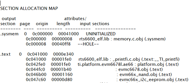
Step 3: Running hex6x Utility
Executed the following command to generate the boot table:
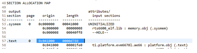
C:\Temp>hex6x led_play.rmd"led_play.out" .text ==> (BOOT TABLE)
"led_play.out" .cinit ==> (BOOT TABLE)
"led_play.out" .const ==> (BOOT TABLE)
"led_play.out" .switch ==> (BOOT TABLE)
Step 4: Convert to i2c / spi format
Here We used both utilities to perform that, We mentioned below.
1. mcsdk_2_01_XX_YY\tools\boot_loader\ibl\src\util\btoccs
2. pdk_c66xx_2_0_0\packages\ti\boot\ibl\src\util\btoccs
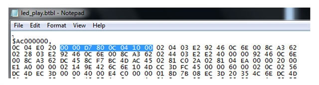
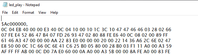
b2i2c led_play.btbl led_play.i2c
b2ccs led_play.i2c led_play.i2c.ccs
romparse nysh.spi.map
here is the content of the nysh.spi.map
section {
 boot_mode = 50
 param_index = 0
 options = 1
 core_freq_mhz = 1000
 exe_file = "led_play.i2c.ccs"
 next_dev_addr_ext = 0x0
 sw_pll_prediv = 5
 sw_pll_mult = 32
 sw_pll_postdiv = 2
 sw_pll_flags = 1
 addr_width = 24
 n_pins = 4
 csel = 0
 mode = 0
 c2t_delay = 0
 bus_freq_mhz = 0
 bus_freq_khz = 500
}
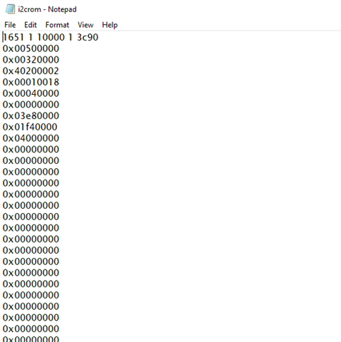
the output file is i2crom.ccs, I changed the value into 00.
byteswapccs i2crom.ccs myLEDapp_le_swap.dat
copy myLEDapp_le_swap.dat myLEDapp.dat
ccs2bin i2crom.ccs led_play_spirom_le.bin
ccs2bin -swap i2crom.ccs led_play_spirom_le_swap.bin
After generating the boot image, we proceeded with configuring the boot mode and flashing the application as outlined below:
1 Configured Boot Mode DIP Switches
-
Set the boot mode DIP switches on the EVM to No Boot / EMIF16 Boot Mode as per the hardware configuration guidelines.
- No Boot off, on, on, on| on, on, on, on | on, on, on, on | on, on, on, on
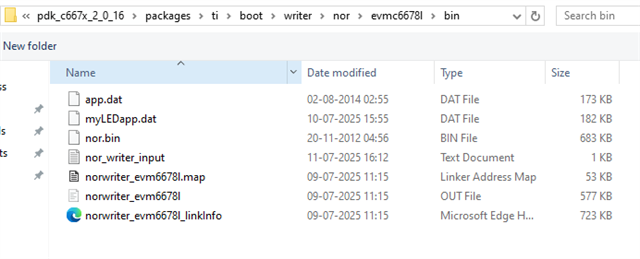
2.Copied Boot Image to NOR Writer Directory
-
Copied the generated
.datfile to the directory:writer\nor\evmc66xxl\bin\
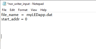
3. Updated NOR Writer Configuration
-
Modified the file
norwriter_input.txtlocated in:writer\nor\evmc66xxl\bin\ -
Made the following changes as per the reference image:
-
Set
file_name=myLEDapp.dat -
Set
start_addr=0
-
4. Connected EVM Using CCS
-
Launched CCSv9 (v9.3.0.00012) and opened the target configuration for the
evmc66xxlemulator. -
Connected to Core 0 successfully.
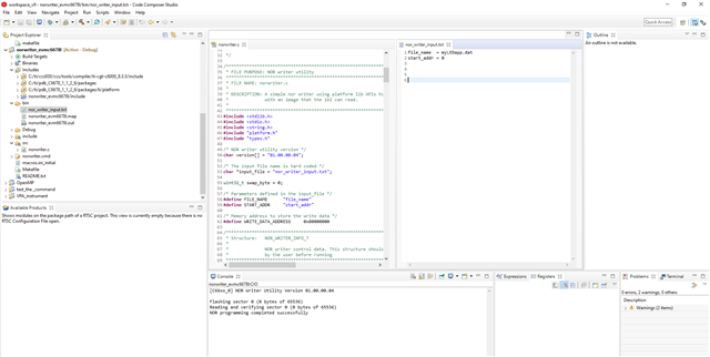
5. Loaded NOR Writer Program
-
Loaded the program:
writer\nor\evmc66xxl\bin\norwriter_evm66xxl.out -
Applied the evmc66xxl.gel script to initialize DDR memory in CCS.
6. Verified DDR Memory Initialization
-
Opened Memory Browser in CCS:
View → Memory Browser
-
Monitored memory starting at address:
0x80000000
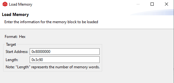
7. Flashed Boot Image to DDR Memory
-
Loaded the
myLEDapp.datfile to address0x80000000:-
In CCS, selected Load Memory and specified the starting address as
0x80000000.
-
Here is the some screenshots for your reference.
Final Step and Observation
After successfully completing all the steps outlined above, we proceeded as follows:
1. Powered Off the EVM
-
Turned off the EVM to prepare for boot mode configuration.
2. Configured Boot Mode DIP Switches
-
Adjusted the EVM DIP switches in accordance with the Boot Mode DIP Switch settings specified in the guidelines for ROM SPI Boot:
off, on, off, off | on, on, on, on | on, on, off, on | on, on, on, on
3. Powered On and Observed Behavior
-
Upon powering the EVM back on, instead of observing the expected LED blinking behavior, we noted that only four LEDs remained constantly illuminated.
-
This suggests that the application did not execute as intended during the SPI boot process.
-
This observation suggests that the SPI boot sequence might not be completing successfully.
Request for Assistance
We would sincerely appreciate it if you could kindly review the steps we have followed and provide guidance on the following:
-
Are there any additional settings or configurations required to enable successful SPI boot on the C6678 EVM?
-
Could there potentially be an issue related to memory mapping in the
led_play.rmd,.btbl, or other boot image generation files? -
Are there any known constraints or dependencies in MCSDK v2.01.02.06 and pdk_c667x_2_0_16 that might impact SPI boot functionality?
-
Could the issue of four LEDs remaining constantly illuminated (instead of the expected blinking behavior) indicate a specific misconfiguration or boot failure?
Your expert guidance and recommendations for resolving this issue, particularly regarding the LED behavior during SPI boot, would be highly appreciated.
Warmest regards,
Krishn Singh Chauhan